Thesis # MEE09:81
Improving QoE over IPTV using FEC and
Retransmission
Master’s Thesis in Electrical Engineering with emphasis on
Telecommunication
By
Ubaid Tariq & Munther Abualhana
Department of Telecommunication Systems School of Engineering Blekinge Institute of Technology (BTH)
This dissertation is to be submitted to Department of Telecommunication systems, at
School of engineering Blekinge Institute of Technology BTH, as a requisite to obtain
degree in Master’s of Electrical Engineering. The dissertation is equivalent to 22 weeks
of full time studies.
Contact information
Writer(s)
Ubaid Tariq
E-post: Tariq.ubaid@gmail.com
Civic # 820625-2556
Munther Abualhana
E-post: munthr@hotmail.com
Civic # 760712-2798
Examiner
Karel De Vogeleer
E-post: karel.de.vogeleer@bth.se
Sektionen för datavetenskap och kommunikation.
Acknowledgement
Our thanks and gratitude to all those who have helped us in giving us support throughout performing our dissertation. First of all we would like to thank Karel De Vogeleer for his support and accepting the proposal and believing in our work and assumptions on behalf of Blekinge Institute of Technology (BTH). His comments on our presentation and proper feedback on our proposal made us achieve this goal.
We are both thankful to our parents who had been praying, all along for us during this time of hardwork and constant concentration to choose quality work. Special thanks to Mr. Waqas Ahmed Imtiaz who helped us in collecting raw data for this thesis and coming up with sharpening our ideas. This thesis work gave us a big opportunity to study something really new and brainstorm on an utterly new area of research.
At last but not the least, both of us had a wonderful time in writing down this quality work and considering BTH to be the utmost source of handling information and playing with the tools to simulate our work.
Abstract
IPTV (Internet Protocol Television), a new and modern concept of emerging technologies with focus on providing cutting edge high-resolution television, broadcast, and other fascinating services, is now easily available with only requirement of high-speed internet. Everytime a new technology is made local, it faces tremendous problems whether from technological point of view to enhance the performance or when it comes down to satisfy the customers.
This cutting edge technology has provided researchers to embark and play with different tools to provide better quality while focusing on existing tools. Our target in dissertation is to provide a few interesting facets of IPTV and come up with a concept of introducing an imaginary cache that can re-collect the packets travelling from streaming server to the end user. In the access node this cache would be fixed and then on the basis of certain pre-assumed research work we can conclude how quick retransmission can take place when the end user responds back using RTCP protocol and asks for the retransmission of corrupted/lost packets. In the last section, we plot our scenario of streaming server on one side and client, end user on the other end and make assumption on the basis of throughput, response time and traffic.
Contents
1 Introduction
1.1 Motivation ... 1
1.2 Goal/Aim ... 2
1.3 Parameters ... 3
1.4 Methodology ... 3
2 Background
2.1 Overview ... 5
2.2.1 Features... 6
2.1.2 Tools ...7
2.1.3 Pros & Cons...7
2.2 Protocols & Distribution schemes ... 8
2.3 Transport Protocols ... 9
2.3.1 Transport Control Protocol TCP ... 10
2.3.2 User Datagram Protocol UDP ... 10
2.3.3 Datagram Congestion Control Protocol DCCP ... 11
2.3.4 Microsoft Media Server Protocol MMS ... 11
2.3.5 Real time Protocol RTP ... 11
2.4 Content Distribution ... 11
2.4.1 Unicast Distribution ... 12
2.4.2 Mulitcast Distribution ... 12
2.4.3 Peer-to-peer (P2P) Distribution ... 14
2.5 Real Time Protocol (RTP)... 15
2.5.1 Components of RTP ... 15
2.5.2 Real Time Control Protocol (RTCP) ... 16
2.6 Session Classification ... 17
3 Texture
3.1 Why Unicast & Multicast? ... 20
3.2 VOD in Unicast ... 22
3.3 Unicast Metrics ... 22
3.3.1 Packet Loss ... 22
3.3.2 Packet Jittering ... 23
3.3.3 Delay ... 23
3.3.4 PID ... 23
3.3.5 Program Clock Reference (PCR) ... 23
3.3.6 Media Delivery Index (MDI) ... 23
3.3.7 Delay Factor ... 24
3.3.8 Media Loss Rate (MLR) ... 24
3.4 IP Mullitcast Vs Application layer Multicast ... 25
3.5 Application layer Multicast Protocols... 26
3.5.1 Appliction layer mulitcast types ... 27
3.5.2 Deploying ALM protocol ... 27
3.6 Topologies in ALM ... 28
3.6.1 Mesh first approach ... 29
3.6.2 Tree first approach ... 30
3.6.3 Implicit approach ... 31
3.6.4 P2P overlay ... 32
4 Quality Metrics & Encoding Techniques
4.1 Fidelity ... 35
4.2 Spatiality ... 36
4.3 Temporality ... 36
4.4 Standards for Video Compression ... 37
4.4.1 MPEG-2 ... 38
4.4.2 MPEG-4 ... 38
4.4.3 H-264 ... 38
4.5 Packet loss: Origin & Outcomes ... 39
4.5.1 Impact on IPTV ... 39
4.5.2 QoE/QoS IPTV ... 40
4.6 Quality of Network Metrics ... 40
4.7 Video Quality Metrics ... 42
4.8 QoE/QoS Metrics ... 42
4.9 Measurement Techniques ... 43
4.9.1 Objective measurements ... 43
4.9.2 Subjective measurements ... 44
4.9.3 Indirect measurements ... 44
Summary ... 45
5 Error Resiliency Techniques with focus on Retransmission
5.1 Forward Error Correction (FEC) ... 47
5.2 Adaptive Forward Error Correction ... 48
5.4 Error Concealment ... 49
5.5 Payload Interleaving ... 49
5.6 Bandwidth Adaptation ... 50
5.7 Scenario ... 51
5.7.1 Procedural description ... 53
5.7.2 Hypothesis ... 53
5.7.3 Necessities ... 54
5.7.4 Validation... 54
5.8 Design ... 55
5.8.1 Compilation ... 55
5.8.2 Request approach (RTCP)... 56
5.8.3 Request approach (RTP) ... 56
5.9 Retransmission Protocol ... 57
5.9.1 Retransmission messages ... 58
5.9.2 Retransmission request messages ... 58
5.9.3 Retransmission response messages ... 59
5.10 Types of Transmission ... 59
5.10.1 Unicast retransmission ... 59
5.10.2 Mulitcast retransmission ... 59
Summary ... 61
6 Simulation
6.1 Overview ... 64
6.2 Goal ... 64
6.3 Scenario ... 64
6.4 Results ... 65
6.4.1Task time response ... 65
6.4.2 Traffic received ... 66
6.4.4 Analysis ... 67
7 Conclusion & Future Work ... 72
8 Addendum ... 75
Chapter 1
Introduction
1.1 Motivation
Broadband access network has given a new interface to usage of IP networks, in fact it made the out of fashion television services i.e. instead of using substitute for distributing channels, a dynamic bandwidth access network makes it possible to go against the old method. IP telephony and television are some paradigms. This gave a huge range of options to us to use some of the very well known internet multimedia applications along with the immense increase in the usage. A window of opportunities was clearly viewed by the ISP’s to install Internet Protocol (IPTV) services. A new world of applications was anticipated.
· Full/Vibrant usage of complete bandwidth would give us a wide range of selecting TV channels.
· Different subscribers could come up with different choices. · Better quality of TV channels.
· Interactional application.
Most of the applications relating IPTV are prone to packet loss. This fact can make a real impact on Quality of experience of the consumers and it should be, somehow, offended. IPTV application and services are spread over IP supported network, which certainly makes use of RTP and RTCP [1]. Thus a packet loss due to the scenario which encodes the video can lead to image destruction quite easily.
How to become flexible against packet loss?
By selecting the following two best techniques, we can surely recover/avoid packet loss, keeping in view their working process.
· Addition of redundant data can make recovery from packet loss quite easier (FEC). Redundant data can be used by the receiver to recover from so called the lost data or
packets. This extra data can be either inserted during the encoding process or during the transport.
· Resending/retransmitting the data or the lost packets. Client can ask for the retransmission of the lost data.
Though the above two techniques provide recovery to most of the packet loss, yet they posses some portion of drawbacks stated as under.
· In large multicast networks, FEC cannot be as fruitful as seen because such a network, the packet loss might occur for a small tree and it might be able to occur for a larger network. Thus it means that for some parts of the network, FEC can be very strong which means that the consumption of bandwidth exceeds, which is wastage. Conversely, FEC can be too weak which doesn’t offer sufficient recovery.
· To get enough recovery, the protection process should be improved, which will lead to enhancement is bandwidth and affects all the users.
· For retransmission to be fruitful enough, IPTV users need packets to be buffered. As the buffered packets arrive too late, for this reason we need buffer packet so that packet wastage is stopped.
· Users of IPTV expect a witty response from the provided service, so the delay at the start must be as little as possible.
In a large multicast network, to apply the technique of retransmission from the source of TV to the outdoing number of subscribers might not be clever enough just because multiple subscribers can ask for retransmission at the same time instant, which probably can burst and overload the streaming server.
So, for large multicast distributed networks retransmission may not be suitable enough. An alternative can be, to apply the technique to the specific sub trees of the large multicast network. This can be easily adopted by the local networks and it will not also influence the entire network. Also retransmission can be applied to parts of the sub network where packet loss happened.
1.2 Goal/Aim
The main focus of this dissertation is to come up with a better understanding of IPTV and an overview of how mechanism of IPTV multicast distributed network takes place. Limitations of IPTV and making comparison of two famous protocols TCP and UDP and providing an overview
of both, how they perform in audio/video streaming. A slight introduction to how packet loss takes place in IPTV and methods of recovery.
1.3 Parameters under focus
· To achieve our goals, we have to focus on following set of parameters · Impact of packet loss on IPTV’s distributed applications.
· Techniques good enough to provide flexibility, error recovery for IPTV streaming application.
· How can we use real-time protocol to provide fast retransmission in IPTV multicast stream delivery.
· Measuring packet retransmission on basis of error resiliency. · Factors that manipulate the act of RTP retransmission mechanism.
· Kind of network for which the RTP based packet retransmission can be implied to successfully encounter error resilience mechanism.
· Application layer multicast, VoD (Video on Demand)
· Data throughput, application response time, average response time.
1.4 Methodology
We will investigate about the above defined parameters as follows: · IPTV and transport protocol
· IPTV technologies · Encoding techniques
· Resiliency and error recovery techniques · Results of packet loss in a IPTV application · Measuring feature metric and techniques. · Using TCP and UDP as model protocols · Extracting results on the basis of simulations.
Chapter 2
Background
2.1 Overview
IPTV stands for Internet protocol television. With IPTV we usually mean distribution of television/video content over a controlled IP network. The process works by delivering the consumers information through a set-up box, which in a way is connected to its broadband connection. The name here doesn’t fully gives the meaning of delivering all the information over internet, it means that only IP protocol is used. Video streaming over internet shouldn’t be looked upon as IPTV [3].
Certain key attributes managed by an IPTV service are as [3]:
End to end/partially closed network Services are offered by sole provider which provides
means of IPTV services available: Access to content, network composition/ structure, a setup box or a decoder at the user’s end, decode and receive data of IPTV content. The services delivered may depend upon multiple distributors offering.
Services are bounded The available services of IPTV are bounded to perform according to the
structural composition. The strength of the service depends upon the area where the service provider has control, moreover, sufficiency in bandwidth is observed.
Services are provided by the service giver The IPTV services are used by the subscribers,
which are solely provided by the service provider, later on, in future the services may be offered by the end user’s as well.
Authorized and admission controlled service before any user can access for IPTV services, it
is checked for appropriate authorization, weather the user has the access to make use of the contents or not. The services are only offered when a minimum required bandwidth is claimed and available, otherwise not.
· The service is open to everybody and anyone with internet access of any bandwidth can make use of video streaming.
· Services can be provided by anybody e.g. a television channel providing a live stream of any movie or an individual making a video for small number of users.
· No authorization/admission required to view video streaming of any kind. No resource reservation or guaranteed delivery of required video etc.
Fig. 2.1 A common comparison of internet and IPTV
2.1.1 Features
The main difference between IPTV and today’s television is that one gets a rare choice of selections between the limited numbers of qualities offered at using IPTV. There is a versatile range of services/options being offered in typical Internet protocol television. A two way high aptitude communication takes place between the user and service provider, which makes a more elaborated service going on between the user and service provider. For instance the user requests for a movie from a TV-guide and it is delivered to the user. Other well known features
that can be provided are interactive and transactional applications which can include a video blog or online shopping. Other prominent traits are as:
· VoD (video on demand) which is a kind of own personal video store with the facility of watching movies of your own choice.
· EPG (electronic Program guide), a full interaction with our own personal needs.
· PVR ( Personal Video recorder) with all possibilities of playing, pausing, forwarding and reversing your video
· Personalized advertizing.
2.1.2 Tools
The two main protocols used for IPTV are IGMP version 2 and RTSP (explained in section 2.2). There are of course other protocols as well, for sending live TV multicasting is used. The providers of IPTV in Sweden use MPEG-2 for media distribution. In the table below, it is quite obvious that to view full quality, SDTV would require 4-6 Mbps bit rate [5].
Fig 2.2 Common IPTV standards
2.1.3 Pros & Cons
The major drawback is the lack of high bandwidth, though now-a-days it is indeed very common to have a high speed internet connection, yet it is quite a problem in under developed countries, unlike Sweden where 80% of the houses today have high broadband facility. Entire networks have to be built so that point-to-point QoS can be satisfied, which is of course not the case today. Set-top box is an expensive digital portion of the IPTV technology, yet obligatory if one has to view another channel on a different TV. On the contrary, IPTV can provide a higher quality for subscribers. It can be offered in HD format, providing the viewers a different experience of television. In fig 2.1.4 a graphical resolution of PAL, NTSC, SD and HD television is presented. From the graph it is evident that a high definition signal can elaborate information then the current television solutions.
A higher value of services for the users is also delivered. Properties which can be used with the traditional TV are also on list of IPTV’s aspects. For instance, pausing of a live TV and then resuming it later on is a feature. A variety of list of channels is another feature along with interactive applications etc. An effective decrease in cost can be observed when services provided of IPTV over the IP network are easily brought down to combine in a structure of ISP. The IPTV services are available when a broadband connection is at service which can be easily provided by the ISP.
[5] Video resolution in various standards
2.2 Protocols and distribution scheme
Our focus in this section is to provide details on the protocols used in IPTV technology; furthermore an introduction to video encoding techniques is given to provide a general concept
of how packet loss might impact the IPTV services. Over all the following topics shall be discussed.
· Video encoding techniques. · Technology used in IPTV · Transport protocols practiced. · Sources and outcomes of packet loss · Error resiliency techniques
The compression and digitizing of all audio/video must be done in order to distribute the material of IPTV. Different multimedia streams which include audio and video and also some other optional streams e.g. subtitles can be sent as single entity or combined. There are advantages and disadvantages of separate and combined delivery. Combined delivery is not as complex because it doesn’t require out of band synchronization. Moreover, the concept of multiplexing at this stage guides to a lessened consumption of network address and ports, which is in a manner an advantage whenever there is a shortage of addresses. On the hand, separate delivery provides lot of elasticity regarding the distribution of a single or multiple streams. In combined delivery, the streams are to be multiplexed and positioned in a transport container, providing an efficient delivery via streams. The most common type of multiplexing method is MPEG-TS (MPEG- transport stream). This multiplexing procedure provides many purposes regarding audio/video synchronization features, such as synchronization of streams that are transported in a way such that the receiver can synchronize the stream and decides when or when not to display streams. MPEG-TS will also provide us with the property of error correction, which shall be discussed briefly in the upcoming chapters.
The encoded streams are transmitted directly whenever the audio and video streams are not multiplexed. By not adding the transport container or transmission using a suitable protocol, a separate stream delivery is ensured. At last, packets are received by the IPTV user, when they are sent using a transport protocol over an IP network.
A number of protocols can be used for the deliverance of IPTV contents but it depends upon on a number of factors, which are to be viewed before they are implemented. These factors can be reduced down to a number of three by summing up all the facts. Firstly, dependency on the type of video service offered: for instance live broadcasting of a television is a totally different THING in comparison with on demand videos. Secondly, when multiple users receive broadcast contents simultaneously, only a few protocols provide guaranteed delivery of broadcast or multicasting. Lastly, the suitable selection protocol also depends upon two factors of IPTV applications.
1. Delay 2. Latency
So, keeping in view the above mentioned facts, the following protocols are adopted as a mean of practicing IPTV applications. We will discuss the above protocols and there structure, how they make up together to perform the audio/video streaming.
· Real transport protocols Transport Control Protocol(TCP),User Datagram Protocol(UDP) and Datagram Congestion Control Protocol(DCCP)
· Application layer protocols Microsoft media Server Protocol (MMSP) and Real-time
transport Protocol (RTP)
2.3.1 Transport Control Protocol (TCP)
TCP is mostly used for reliable data transmission, in other words a connection oriented protocol which uses full-duplex association for reliable transfer of data [7]. A unique process in TCP is that the receiver can process and receive sufficient data or as much as it is required in time by the receiver by two ways. One is by means of sequence numbers in which TCP provides arranged delivery secondly a flow control mechanism which ensures the amount of data that can be absorbed by the receiver. TCP can adopt congestion and provide reliable data transfer by the two mechanisms opted i.e. a packet retransmission mechanism and congestion avoidance mechanism. This utility however imposes couple of restrictions on distribution of streaming data: TCP provides us with the surety of data delivery in time. If data loss or packet takes place, then for sure the receiver would wait for retransmission of data, in the meanwhile the buffers may under run. If TCP adapts to congestion, a constant throughput cannot be assured. This means here that the application receiving the contents needs a buffer to settle in the dynamic
transfer throughput. Moreover, TCP establishes the connection by three way hand shake, which is time consuming. These aspects make TCP become suitable for applications that necessitate low latency content delivery and fairly not suitable at all for applications that require lost of data over high latencies.
2.3.2 User datagram Protocol (UDP)
UDP is a connectionless protocol with limited functionality, which means that the sender and receiver have no dynamic connection [8]. It means that this connection type doesn’t provide us reliable data delivery, flow control, congestion control, suiting of data rate to capacity of network and receivers processing speed. In UDP transmission, the sender only determines the transfer rate and no idea or process to make sure that the data is received by the receiver or not. Also there is not feedback on transmission control. By using broadcast or multicast, UDP oriented connection send data to multiple users. Unlike TCP, UDP doesn’t take time to establish connection, which doesn’t lead to delay in data delivery and transfer.
2.3.3 Datagram congestion control protocol (DCCP)
DCCP is a recently developed protocol, which fuses together the concepts of TCP and UDP. It provides controlled yet unreliable delivery of datagram over bidirectional unicast connection. DCCP is eccentric in a way that it provides a tradeoff between timing factor from UDP and congestion control from TCP, thus making it suitable for applications that have strict timing constraints yet benefitting from congestion control e.g. Voice over IP and video streaming.
2.3.4 Microsoft media server protocol (MMS)
Microsoft’s MMS protocol is a collection of protocols used to stream multimedia from streaming server to media player. It can use UDP, TCP or RTP for the delivery of the contents. The protocol is however closed, but it is used by several other multimedia applications such as VLC and Winamp as the protocol supported only Microsoft’s media applications.
2.3.5 Real time Protocol (RTP)
The protocol shall be discussed in the later section. [1]
2.4 Content Distribution
Four methods are used as for distribution of content in IPTV service. These four methods are stated below, depending on the type of application to be used.
1. Unicast distribution 2. Multicast distribution 3. Peer to peer distribution 4. Hybrid distribution
2.4.1 Unicast Distribution
Unicast distribution protocols: UDP, TCP, RTP, DCCP and MMS are the common choices used for Video on Demand services because protocols like TCP are used where high latency is required along with the factors of reliability and connection orientation, So low latency such protocol is not used for services that require low latency. What happens is that, an IPTV user connects itself to a streaming server for IPTV contents. Once the connection has been established, the users then continue using the IPTV content. Prerecorded data can also be sending as disintegrated data. In this case, the rate of data transferred is higher than the required rate to receive the application.
For broadcast TV, unicast distribution is ineffective because of the services provided by the service provider for IPTV. For instance, N users need N numbers of IPTV streams are to be transmitted over the same network.
2.4.2 Multicast distribution
For efficient delivery of IPTV to multiple clients of IPTV, multicasting distribution is preferred for such simultaneous process e.g. delivery of a live broadcast.
A combination of UDP and RTP is together used as transport protocols, as UDP’s limited functionality for low latency multimedia content distribution; RTP is fused with it providing an availability of feedback mechanism.
Classically, TV channels are multicast in the core network and are remain in the access network, not forwarded unless clients request for the respective channels. Access network has limited bandwidth capacity as compared to the core network just because of the fact that the IPTV stream is only forwarded to the user when the user has made request for it, otherwise not. An IPTV service provider can offer more channels, which technically possible with the traditional broadcast TV. The only disadvantage of this mechanism is that in IPTV with limited bandwidth, the channel is present, only the stream has to be requested, while in the traditional broadcast channel is present in user’s range
To enable multicasting, two protocols of immense importance are to be activated. Protocol independent Multicast-Sparse mode [11] (PIM-SM) and internet group membership protocol (IGMP) [12]. PIM-SM is a routing protocol for multicast group; it executes some of the most important multicast tasks. Also allows routers to alert each other for number of available multicast channels and multicasting routing functionalities, including of setting up of a new
multicast path from a source to multi content seeking receivers. IGMP is a subscription protocol which allows clients to subscribe to multicast groups by means of sending membership reports. Access node routers make use of IGMP protocol to determine which users are interested in definite multicast group and also determine which packets are to be send from a specific multicast group, to the which routers port.
Fig 2.4.2 Multicast environment
In the above figure, a typical example of IPTV distribution network is provided. The whole stream is multicast from the streaming server to the Set top box (STB). STB is equipment with the user that decodes the video stream and plays it to the TV. During the whole process, the video stream navigates across three different networks; Core network, access network and home network. Core network is maintained by the service provider, access network which is the middle connection between the service provider and home network and lastly, home network is the network found in users region. Access network and home network are interconnected by a home gateway (HG). HG is a component which allows home devices such as PC or STB to get connected with the outside world. The access network and core network are connected by Multi Service access node (MSAN). MSAN is a device which assimilates different multimedia services like telephony, television and internet on a single platform, from there offering connections to different access nodes. In the figure, a stream is received by subscriber A and B, while the other is forwarded to C. When a user requests for IPTV service, the STB will issue a request to its belonged multicast group by means of IGMP report. Clearly home gateway HG will receive this
information, when HG will receive the packets; the packets are forwarded to the user. Otherwise it will forward the request to MSAN. The MSAN upon the reception of the request, will forward the packets to the requested user. The stream shall be received by STB and displayed.
2.4.3 Peer-to-peer distribution (P2P)
A new and upcoming technology is the use of Peer to peer overlay networks in IPTV technology to distribute IPTV contents from a service provider to IPTV clients. In a p2p overlay network, the contents of IPTV are distributed partially or entirely amongst peers. One interesting thing in this scenario is that the client receiving the IPTV content will not only be consuming data, but also allowing it to be shared by other peers, which are interested in data. If we look at this distribution from operator’s point of view, it is highly preferred by the operator, as it is a cheap distribution technique because the bandwidth required to view the IPTV contents is shared by the IPTV nodes and the network becomes highly balanced.
For streaming in IPTV applications, users would like to watch the streaming TV right from the moment when they start using the application, unlike the packet distribution in typical p2p applications e.g. Bittorrent [13], Gnutella etc in which the order of the data received is not important as the user would directly use the file when the transferring of data is done. In IPTV, this implies that the order, in which the data is received, is important; a user here is only interested in data that is immediately followed by data currently being decoded and displayed. Thus for this kind of application, a tree is needed with nodes receiving data from higher nodes in the distribution tree. This means that a large playback interval can infer between the nodes transmitting the contents from top and the nodes that are at the edge of the tree. This also means that the dynamic availability of resources is also very dynamic as the users of IPTV are constantly joining and leaving the services. A large pre buffer is needed here to avoid buffer under run due to the dynamic behavior.
2.4.4 Hybrid distribution
Hybrid distribution is also very common now a day. Hybrid distribution combines content distribution methods to optimize content delivery. The two factors to be optimized are startup delay and network distribution costs. In multicast IPTV start delay is caused by the IGMP subscription. It can be reduced by starting up an IPTV connection via a unicast method with a streaming server. This will setup a connection very quickly and the data would be received as fast as possible. While the content is being displayed by the IPTV, client joins the multicast group and once the data from multicast group is received, the client can then switch from unicast stream to multicast stream.
The same rule can be used to lessen startup delays for p2p based IPTV distribution. In this case, the streaming server can be used for operation of two functions: one is to allow small startup delays and secondly function as a backup data resource, for which IPTV can directly connect to streaming server for the missing part of the stream.
2.5 Real-time Transport Protocol
The real time transport protocol RTP [1] is type of protocol designed for the transfer of real time applications over internet. RTP was designed to support real time applications which have low latency e.g. telephony, video conferencing and IPTV. Along with UDP, RTP also supports TCP. UDP runs on top on RTP [8]. RTP neither provides guaranteed delivery of data nor it provides any reliability, but its specific feature is the streaming of multimedia data.
2.5.1 Components of RTP
· Real-time data transport
It can be a combination of audio/video streams as a single or both. For the transport of the stream, a transport protocol such as UDP or TCP is needed. Support of UDP is mandatory, TCP is not a must.
· RTCP (Real time control protocol) for monitoring and signaling of a session.
The edge that RTP has over other protocols is that it provides means of transport for multimedia streaming and it is used for low latency applications such as IP telephony and video conferencing. RTP provides support for multiple stream transmission at the same time, which provides flexibility in delivery of single or combined audio or video streams and the synchronization factor in RTP provides room for streaming situations. Above is the header format of an RTP protocol. It has certain fields that make RTP useful enough to support low latency multimedia applications.
Fig 2.5.1 RTP header format
· Payload type PT (7 bits) Used to define several types of existing payload type’s along
with a variety of dynamic payload types. See section [14] and [15].
· Sequence number SN (16 bits) is used to send and receive packet loss and provides
· Timestamp TS (32 bits) is used for providing synchronization of multiple steams,
enables receiver to playback the samples at appropriate intervals and calculate jitter between the sender and the receiver.
· SSRC Synchronization source (32 bits) the source of RTP packets. SSRC contains a
32-bit randomly created identifier such that all the members of RTP session can uniquely identify the source of RTP packet stream without depending upon the network address. This is a convenient because RTP packets may get combined or mix up during the transport.
· Contribution source CSRC RTP uses CRSC to know the source of all the packets that
were mixed up from different streams by a source.
2.5.2 Real time control protocol (RTCP)
Real time control protocol provides a check process on sender and receiver involvement in the RTP session. Monitors RTP’s function for the ongoing session, mechanism for providing identification of the participants involved in the transport and least control over RTP session. For this reason RTCP provides reports on sender and receiver:
· A sender report is used by the senders to provide statistics on transmission and reception.
· Whereas, a receiver report provides stats on a member that is not involved in updating the data.
RTCP reports are sends out at periodic intervals in the session to all the participants. By sending out RTCP reports every participant keeps a record of number of members in a session and therefore it can calculate its share of RTCP bandwidth and interval of RTCP report. There is however constraints on applications provided by the RTCP, such as; higher the number of participants joining the session, higher the interval for transmission of RTCP reports. Thus for
group with larger number of broadcast group, the feedback process will subtle because feedback process duration will be too high to provide and detect solutions to problems. RTCP reports are useful because the problems during the RTP session can be easily identified, reported and solved very quickly. For example, the sender could easily reduce the transmission rate of packets when receiver is facing a huge packet loss. A figure of receiver report is shown in the upcoming topic,
which informs the receiver about the packets the receiver received, packets that were lost during the transmission and jitter occurred between the arrivals [16].
2.6 Session classification
Before the start of an IPTV session, it is important to let the receiver know about the number of available streams, how the stream shall be delivered and the important constraints associated with the streaming session. All the required info and the parameters shall be exchanged in advance and before the establishment of the session. A common protocol for describing the session durations of the multimedia is the Session Description Protocol (SDP) [17]. The description of SDP contains media and transmission properties along with, maybe, a description of the content. To send and receive SDP information and contents, different protocols are used
·
Session initiation protocol SIP·
Real-time streaming protocol RTSP·
Hyper text transfer protocol HTTP·
Session announcement protocol SAP[20] Fig 2.6 RTSP structure
HTTP [18] is usually used for transfer of data over World Wide Web (www) and can also be used to sporadically reclaim information on streaming sessions. The session announcement protocol (SAP) [19] gives notice of multicast session via multicasting. Those entities which are keen to
extract information about the available sessions listen to a familiar multicast address to receive updates provided by the SAP. The SAP description is announced after regular intervals. The Real time Streaming protocol RTSP [20] is used to control streams of continuous media such as audio/video. RTSP is described as a remote control for the network of streams, allowing the applications users to pause and resume the stream and search for particular contents. RTSP message syntax is similar to HTTP syntax. The session initiation protocol (SIP) [21] is used as a signaling protocol used to create, modify and terminate streaming sessions with one or more service users. SIP protocol is also used for instant messaging.
Chapter 3
Texture
Before we explain the concept of multicasting in detail for IPTV, let us provide a simple discussion where we would be able to make a clear difference between choosing either Unicast or Multicast for IPTV. Some of the very fine aspects of IPTV are to be focused in this chapter. Before we proceed forward into providing details on multicast, let us say on what are we going to provide in this chapter. A unique discussion on defining multitask process in IPTV would be a major task under focus in this chapter, including a list of techniques and providing a quick review of how multitasking takes place in IPTV environment. Architecture, design of a multicast environment, protocols used a service model and how all these concepts merge at application as well as network layer, shall be discussed.
3.1 Why Unicast and multicast?
Our main focus in this chapter would be to provide architecture for reliable delivery on IPTV stream, focusing on different parameters. IPTV was designed to support primarily unicast protocol, to move data from a single source to single receiver. However, it can also support multicast, with more than one destination to deliver the service. IGMP more commonly Internet
Group Management Protocol manages [12] the entire multicast in IPTV stream. Every piece of
document provides a long discussion on IGMP but in our refined work, we shall focus on Application layer management (ALM) and topologies associated.
Let us consider multicast, when we compare it with unicast, it is obvious that the stream can be delivered to many users at the same time in multicast [23]. Every channel that has to be broadcasted has a unique multicast group. Using IGMP the end users receive broadcast packets and then the entire stream via the network. One drawback in multicast is that it there is no reliability to packet loss, once a packet is lost there is no such thing as error recovery.
The figure below provides multi users are using an IPTV stream via broadband setup. Each end user (home) in the above figure is a part of multicast stream delivered by the IPTV server. This scenario shows how multi users access different demands at the same time consuming bandwidth.
[22] Fig 3.1 Broadcasting in multicast
Figure below provides a contrast to a multicast environment, unicast Video on Demand (VOD) [6] as described in chapter 2. IPTV stream is sent from a VOD server to an end user. There is a separate content delivery stream for each user to deliver VOD. If the above stream is to be delivered as an MPEG [26] or H.264 [27] a higher stream of data may be required. So an obvious facet of unicast protocol is that bandwidth consumption for a particular network can increase instantly.
3.2 VOD in Unicast
At this stage we will discuss a specific unicast feature VoD (Video on Demand), which would provide a clear idea of why we used unicast technique for above designed cache. IPTV uses multicast and VoD uses unicast technology. Unicast scenario is unique, because it has a single IP address and associated with a single IP is a single user. However, if the same data is to be sending more than once to the same unicast address, then the data has to be sending again and again for the same user. To support either unicast or multicast, the end user needs to support two major protocols: RTSP [20] (Real-time streaming protocol) for VoD and IGMP for multicast.
RTSP is used for two purposes, to establish and to control one or single streams of continuous data e.g. audio and video. However, RTSP is not able to deliver the continuous data itself rather it uses the services of RTP to transfer streaming media but its transport mechanism is not influenced by the way how continuous data is carried out.
IGMP on the other hand is used in multicast to carry out the management of the entire IPTV network. The entire core and access network is provided diagrammatically in chapter 2. IGMP is used in an efficient way in an IPTV environment by providing ease for which leave and join the network simultaneously.
For both techniques, weather VoD or IPTV, some very well known common algorithms are used. Some of them are discussed in chapter 2, Mpeg-2 [26], Mpeg-4[26] [28], H.264 etc. In all these cases the compressed as well as the encrypted data is send via using MPEG-TS (also discussed earlier in chapter-2).
3.3 Unicast metrics
As we have already discussed some of the important metrics that are required in making a retransmission mechanism more efficient, some common metrics at this stage of an optimal unicast/VoD scenario can also be discussed [29].
3.3.1 Packet loss
Loss in packet takes place when a single or multiple packets fail to reach the desired destination. If the packet loss is related to I, B or P frames, well judged opinions can be made here. If packet loss is related to I frames, the chances are that the video signal can be distorted. If the packet loss is reclaimed in B or P frames, the chances is that less distortion is observed but still image can be damaged.
3.3.2 Packet jittering
Packet jitter is estimating on variance of the data arrival time and interleaving of RTP data packets which are calculated on the basis of RTP timestamp field [15]. It can be defined as the mean difference of time when packets are sent by the server and then received at the destination.
3.3.3 Delay
Networks that are usually packet based, the aspect of delay always exist as it is common for packets to change their routes and sometimes may arrive at different time intervals to be out of order. RTP protocol tries to reduce this problem. As every RTP comprises of a sequence number, it is not possible for the packet to be lost and they are well placed for decoding.
3.3.4 PID
Every TS part of MPEG has 188 bytes fixed length, 4 bytes for the header and the rest of 184 bytes for payload. PID here comes from those 4 bytes and it carries a unique identifier for the type of packet or payload carried by MPEG-TS. Every video/audio needs to have a unique PID. This allows the STB to carry out sequenced decoding.
One thing has to be made sure at this stage for later procession that PID is tasking is carried out systematically and there has to be a precise difference between Payload structure identifier (PSI) and the video/audio stream that has to be reconstructed at the STB for its audio/video contents.
3.3.5 PCR (Program clock reference)
TS as said above, being used as a part of MPEG, contains seven packets of 188 bytes each. In these TS streams are clock synchronizers, which are referred to as PCR, are simultaneous values of 27 MHz system time clock which is located at the mpeg video encoder. A problem here with the jittering of the PCR is that if the PCRs are not received at regular intervals, then the associated clock may jitter.
3.3.6 MDI (Media delivery index)
RFC 4445---is a counting mechanism that transports good or better quality of video in a network by combining jitter and packet loss ratio together, regardless of the encoding techniques. MDI can be used as a tool or as a quality indicator for such networks which intend to deliver quality media such as video, audio, VoD, VoIP etc.
3.3.7 Delay Factor
DF or the delay factor is the maximum delay that is noticed at the end of each IPTV stream packets, when they start to move and at the time when they fully get consumed. This is rather a constant traffic rate at which traffic is consumed by the stream or the certain chunk of packets in the stream. Greater DF values indicate network latency required by a certain stream to be delivered (RFC 4445)
3.3.8 Media Loss Rate (MLR)
Media loss rate is the calculation of packets that are loss or out of order in a certain stream over a specific period of time. These packets are called flow packets and they carry information on streaming application.
Though it is quite clear that unicast is more effective than multicast, but the future of this technology lies within multicast environment because in today multicast is more favored by the server/user environment for video distribution. In the coming sections, we will describe a satisfactory multicast environment for IPTV and discuss how IGMP and PIM protocol work together in IPTV based scenario.
At first we will talk on why multicast is reliable enough for an IPTV environment and how it relates to provide end users the quality they need. Multicast sprouts as an important element when it comes to deploy networks such as IPTV. It provides guaranteed delivery in case of distinctive source applications as IPTV. But reliability in multicast environment for real time applications has always been an existing fact. Betterment in providing QoS for IPTV is necessary. When it comes down to end users to view IPTV, whether it is VoD or IPTV in multicast environment, they always demand best of quality. For a new user to IPTV, the service is really new as well as experimenting. For them, leaving the traditional TV and moving to the new internet-based service might be a shift in expenditure as well as taking chances on making substitutes. Some extra qualities must be provided along QoS, with reducing delay, jitter and congestion.
· Service without interruption
· Corroborated documentation on services associated with IPTV like VoD, TV, broadcasting etc.
· Fast transmission of service and fast re-transmission of service in case of failure of network or if goes down.
3.4 Why choosing IP multicast over Application layer multicast?
The above discussion shows that users in IPTV expect more in order to make them quit or at least consider IPTV as a modern life alternative. In the recent years, there has been a quite drastic improvement in ALM (Application layer multicast) for using in multimedia applications and services like IPTV aswell. ALM is differentiated from IP multicast [24] on couple of facts which really provide it an edge. For instance ALM doesn’t require facilitation of routers and structure of network, though highly cost-effective yet easy to install. Following are some major differences which draw a clear line between ALM and IP multicast [25].
· In ALM, there is no need of routers to maintain information of every group associated with each router in case of IP multicast. Rather this state is maintained at the end user. In case of IP multicast maintain this information at the routers increase transparency and complexity.
· ALM consumes more bandwidth than IP multicast procedures. The reason for this fact is that IP multicast is implemented by routers and instead of sending the same packet over again, it constructs a tree with best possible packet forwarding approach. On the contrary, in ALM no routers are used and packets that are to be send are resend on the same link multiple times on the end user. So this consumes fairly more bandwidth. · As compare to IP multicast, ALM superimposes a network on top of existing network
that is to carry out unicast.
· For delivering multicast data and routing information, a routing multicast tree is constructed. Any single host that enters or joins an IP multicast session informs the concerned router. This status is then shared amongst all the routers via the tree. All this information is carried out at the tree about the user status is carried out through IGMP protocol.
· ALM is more reliable than IP multicast, as reliability is an important factor for a packet sensitive service like IPTV.
· The absence of routers in ALM is drawback when we compare some important facts like latency, low efficiency which are only known in traces to the end users. So the end users in case of ALM have a very rare or no knowledge about what is going on in the network structure.
· Multimedia applications require reliability and in-time delivery of streaming data. In case of ALM more possibilities are offered for error and congestion control for the reliable delivery in multicast group.
· ALM can be easily implemented within the current internet infrastructure as compared to the IP multicast. Why? Because IP multicast requires routers installation of multicast behavior.
By far points, Application layer multicasting is more advantageous than IP multicast system. The reasons are immense and a glimpse is provided. Even in case of IPTV, one can easily deploy this system of guaranteed delivery of streaming data by focusing on certain factors. We will proceed with providing implementing different topological scenarios implemented in IPTV environment.
3.5 Application layer multicast protocols
We will provide a synopsis of all the protocols that by now have been implemented since the very first day when p2p was first implemented on application layer. In an Application layer multicast environment, end users handle all the information regarding which peers want to become a group member and making copies of packets etc. The end system maneuvers itself in such a way that it behaves as a rational overlay network end nodes as edge nodes for multicast to receive the message once, so the network would send all the users a single message once data in unicast environment. Figure shows the architecture of ALM.
.
3.5.1 Application layer multicast types
Over the years many drawbacks have appeared after implementation of ALM in a network. Solutions to these drawbacks have shown up as awareness for topology multicast in an overlay network. This is apprehended to favor multicast environment somehow, depending on the selection of nodes. This can be classified into the following three ways [31].
I. Application layer multicast for overlay network II. Application layer multicast for p2p network III. Application layer multicast for point multicast.
3.5.2 Deploying Application layer multicast protocol
As said earlier, application layer protocols are deployed either at end users or at proxy level [32]. In case of proxy-based ALM, the advantage is taken of the existing IP multicast “mass” and by including an envoy as an overlay node, whereas the proxies themselves are organized into an overlay network and providing maximum security and efficiency. While on the other hand, ALM end users protocols provide forwarding of data as well as multicast utility. End user protocols are rather more flexible, adaptable, provide ease in deployment and handled easily when compared to proxy-based protocol but the end-user protocol can well maintain increasing number of users when it comes down to provide fruitful services.
3.6 Topologies in Application layer multicast protocol
In application layer multicast, two topological orders are deployed that are used to organize group components. First is data topology and the second is control topology. Data topology provides convenience for the packets to follow a certain data path. While the control topology time to time swaps refreshment messages to identify and follow the non-ethical leave of members from a certain group. Now, it depends upon the construction sequence and data path topology, and follows the regular topology under following approaches [34].
· Tree first topology · Mesh topology
· Lopsided tree topology · Implicit approach · P2P overlay
3.6.1Mesh first approach
In this approach, the existing group members transform themselves into overlay mesh topology, so that each member is linked with multiple paths that can be accessed by other nodes. Then it follows an explicit tree which is formed at any member node via a well known multicast process e.g. DVMRP, NARADA and SCATTERCAST.
DVMRP
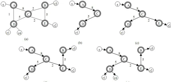
Distance vector multicast routing protocol [33] [34] [35], is a more of a multicast addition to unicast concepts that are used in Routing information Protocol (RIP). Routing information is started by the receiver, a source based routing protocol we can call this. Therefore, a spanning tree is created which performs best with respect to delay, at every node. Using Reverse path multicasting (RPM) each multicast data unit is routed. Techniques like graft-data units and poison-reverse are used to avail control mechanism in such conditions. The figures below represent group of routers that named from A to E. Every router is linked with a cost to get connected to another router. The number with the cost here shows some of the constraints like
Fig 3.6.1 showing DVMRP (a) Multicast (b) r1 joining (b) r2 joining (c) r3 joining (d) r4 joining
end-to-end delay, maximum bandwidth etc .For instance, in the above figure (a) the link from D to C is more costly then the link from C to B. Some of the routers are attached with constants like r1, r2, r3, r4. In reality, these constants can be home users as well, sharing a common video or an online game. For instance, there are more connectivity points from A to D: A→D or A→C→D. The cost of the first path is greater (18) than that of the second path (13). (b) Shows
the shortest path to r1 is from source S to the connected router R. When the rest of the receivers’ r2, r3 and r4 join the network, the tree then further extends to (c), (d) and (e) respectively. In (e) it is quite clearly shown the composition of a distribution tree in a multicast group. It is to be noted here that this tree formed is for one source S, when dealing with the other sources, it becomes more complex.
3.6.2 Tree first topology
Unlike mesh approach, in tree first topology a shared resource data tree is constructed directly. To choose a parent node is an important both from efficiency and performance point of view. To choose an organized parent node is very important for the members of the group because then it becomes easy for the group members to know about the other group members under the same parent node and know about other neighboring members under the same overlay network and establishing links with them. YOID, banana tree, host multicast tree and ALMI are a few examples under this topology.
YOID
Like the above briefly tacit defined protocol DVMRP, YOID [35] [33] is also the first protocol to be deployed in tree topology. YOID directly creates a data delivery tree that has control over the aspects of different tree attachments.
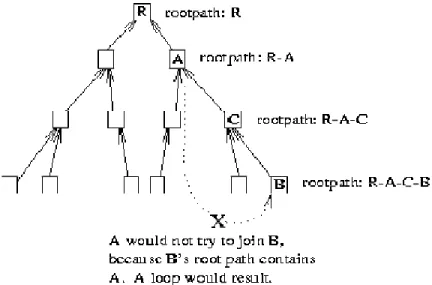
As it is clear from the above structure it is quite clear that unlike mesh, the quality of data is independent of mesh. It also obvious from the figure that YOID has a shared tree and all the members in the group are associated with their own parent node, also each parent has to choose the number of children it can support. Whenever a member wants to join a certain group, it looks for a parent and attaches itself to a certain meeting point. The main design of this protocol is to provide vigorousness and providing a simple tree structure. The structure however may cause loops and bad structuring can lead to poor performance. Certain mechanism had been proposed to avoid this flaw. To use SWITCHSTAMP, and certain algorithms have been proposed such as latency refined algorithm and loss rate refined algorithm.
HMPT
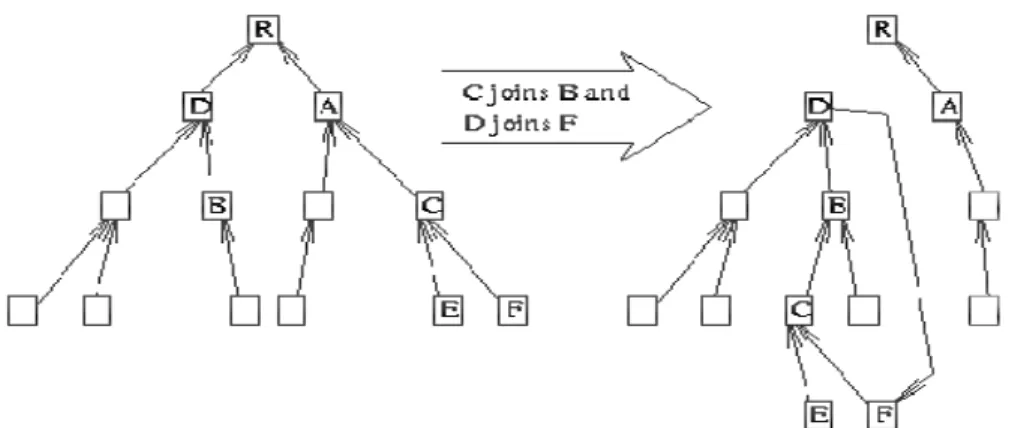
Host multicast protocol tree is another kind of protocol applied in tree topology and uses tree first approach [33] but in performance aspect, it is found to be much better than YOID. A tree in this case is built in a way that highest level at each node is constant and cost to connect every link is minimum. Round trip time for every member in of this group is added as an optimization matrix. The tree of HMPT is more or less same as YOID. All the members in the group are responsible for finding the related parent node, and then attach it via finding the common attach point to the tree.
From the extracted value of Round trip time (RTT), the new comer node finds itself to the closet node among the possible parents and their corresponding children. If the closed node itself is parent node then the new comer would be attached at node R. new then would be accepted as the child to the parent node. The whole process is repeated again for the same new comer node which wants to join the tree by knowing the child of the tree and the possible parents.
3.6.3 Implicit approach
In this approach, all the protocols make up a central topology with specific properties. There are a couple of protocols of this centralized topology named as KUDOS and NICE. KUDOS is within two layered hierarchy and NICE is within three.
NICE
When a new member wants to join or leave a group, this protocol maintains information hierarchy amongst the group members [33]. It is useful for real time applications in large group. It is more of a hierarchy controlled protocol. All the group members are assigned to the lowest level of layer and there they group to form clusters. Cluster size usually varies from K to 3K-1 where K is a constant. There is a leader of each cluster, and the new member joins the cluster on the choice made by the leader.
However the for a new member to join this cluster, the process is very unique and complex too. First the RP is consulted, from which the information of the highest layer member is obtained
Ln and then the closest to this one is obtained. The leader then notifies that the new comer is on the layer Ln-1. This process is carried on until the layer L0 is reached with a proper position.
3.6.4 P2P Overlay
Construction of an overlay network upon an already existing IP network has allowed p2p overlay to gain popularity in the recent times as this scheme has the latency to carry large scale functions successfully. There are two sorts of p2p [33] overlay architecture. One is the structured and the other is the unstructured. In structured overlay connected nodes are managed in a certain order while in unstructured overlay the connected nodes haphazardly. One of the main problems with structured overlay is that agitation is high. This is the only reason why structured overlay is used for application layer multicast. Common examples are KOORDE, TAPESTRY, CAN.
3.7 Constraints based application layer multicast
A certain set of constraints come into action when practically implementing application layer multicast (ALM). However, we can use these constraints to further explore our research and enhance the quality of IPTV stream.
· Extra transparency is caused at the end user while using application layer multicast, as it is implemented as the end user, so this can cause a compromise in IPTV quality.
· ALM is not quite effective when it uses network resources such as when end user is using · ALM, the data packets are get imitated by the end user, so the same set of packets are
send over the same link again and again. This causes congestion on the network.
· As in an overlay network, overlay nodes are pre-ordered haphazardly without knowing which layer is beneath; this is a flaw in application layer as compared to physical layer which is lying in top of application multicast.
· Large trees can built up when same packets are send over the same link again and again. This would cause using more bandwidth.
Chapter 4
Quality metrics & encoding techniques
In this section, we shall discuss the newest technologies in use for video compression along with basic principles. This portion of discussion here will provide us with facts on how packet loss can influence the features of IPTV stream. To discuss particular video format in detail here will be of no use but a summary of common IPTV video formats is discussed. A video compression format called as Codec is derived from compression/decompression. Video footage is either stored or scattered just when the video encoders compress the size of a video signal. This is done by using resources with inadequate storage output capacity, e.g. DVD or a broadband internet connection. To compress a video, 3 basic principles are used to make compression.
4.1 Fidelity
Is defined as a process in which how accurately a compressed image is able to reproduce or generate the original image [36] [37]. There are however couple of options opted by the video encoder; for instance by reducing the color space or decreasing image resolution etc. By reducing the image resolution some details might be lost, but the resulting image after image resolution can be much smaller in size and distorted. In case of reduced color spacing, similar colors might be replaced by color/colors that approximately match the original color. Fidelity in this case can be low, if maximum colors are replaced by a single color. An example here could be replacement of colors with black and white. The figure below shows the example of fidelity in case for image resolution and color spacing.
(c) Color comparison
Fig. 4.1 Fidelity Compression (a) Original, (b) resolution reduced (c) reduced color space
4.2 Spatiality
Shows a relationship between different parts of an image [36] [37], an image, when split up into different small blocks, it is more likely to observe that the neighboring blocks may share the same color, because they are the part of the same object in the image. For instance, if the image is of a big blue box and it is divided into 500 blocks, it is likely to observe that multiple blocks contain same information. A video compressor tires to remove this unnecessary information and save storage space.
4.3 Temporality
It is described as a relation between video frames and subsequent video image. Subsequent video frames tend to contain the same information. Subsequent frames show the same object or parts belonging to the same object because of the changing location of the object. Most of the times, neighboring frames have high similarities so compression can be reached only by storing the differences between two subsequent frames. The resulting compressed image is much smaller in size as compared to the original image without encoding similarities in it. The below two figures show temporal relationship between two subsequent frames. The left hand and the mouth are the two differences in the frames; rest is the same, so it is encoded.
Fig 4.3 Temporal relationship between two frames
There are different types of encoders for different frames; predictive frames and reference frames. Reference frames are those frames that have no temporal relation with existing frames. On the other hand, predictive frames do have temporal relation with the other existing frames. Frames that belong to a reference frame are referred to as Group of pictures (GOP) and the interval amongst the both is knows to be GOP length.
4.4 Standards for video compression
Setting standards for video formats is an important aspect from development point of view. One, a video standard can be used on a large scale, if it had been developed by any manufacturer for interoperable solutions. Two, the cost can be reduced on extending the already developed version by certain manufacturer, as experts would emphasis more on the development of the standard. For instance, a quite doing well standard is the MPEG-2 standard for DVD’s.
There are two very well known organizations working on video and audio coding standards;
· MPEG moving picture expert group. MPEG is working under ISO/IEC and in charge of
audio video coding standards. Standards for products such as CD, MP3, set top box and DVD’s are developed by MPEG [26].
· VCEG video coding expert group works under International Telecommunication union
Standardization sector (ITU-T) focusing on development of new video coding standards [38].
The three key video formats shall be discussed in the next topic, which are most common in use and known: MPEG-2, MPEG-4 and H.264 [28] [26].


![Figure below provides a contrast to a multicast environment, unicast Video on Demand (VOD) [6] as described in chapter 2](https://thumb-eu.123doks.com/thumbv2/5dokorg/4291231.95842/32.918.293.626.252.500/figure-provides-contrast-multicast-environment-unicast-demand-described.webp)

![Fig 3.6 Various topologies (a) Mesh topology (b) Initial Tree (c) Lopsided tree [34]](https://thumb-eu.123doks.com/thumbv2/5dokorg/4291231.95842/39.918.140.780.518.908/fig-various-topologies-mesh-topology-initial-tree-lopsided.webp)