COMPARISON OF MULTIRESOLUTION CONTINUUM
THEORY AND NONLOCAL DAMAGE MODEL FOR USE
IN SIMULATION OF MANUFACTURING PROCESSES
Olufunminiyi Abiri, Hao Qin,
∗& Lars-Erik Lindgren
Lule˚a University of Technology, 97187 Lule˚a, Sweden
∗Address all correspondence to: Hao Qin, E-mail: hao.qin@ltu.seModelling and simulation of manufacturing processes may require the capability to account for localization behavior, often associated with damage/fracture. It may be unwanted localization indicating a failure in the process or, as in the case of machining and cutting, a wanted phenomenon to be controlled. The latter requires a higher accuracy regarding the modelling of the underlying physics, as well as the robustness of the simulation procedure. Two different approaches for achieving mesh-independent solutions are compared in this paper. They are the multiresolution continuum theory (MRCT) and nonlocal damage model. The MRCT theory is a general multilength-scale finite element formulation, while the nonlocal damage model is a specialized method using a weighted averaging of softening internal variables over a spatial neighborhood of the material point. Both approaches result in a converged finite element solution of the localization problem upon mesh refinement. This study compares the accuracy and robustness of their numerical schemes in implicit finite element codes for the plane strain shear deformation test case. Final remarks concerning ease of implementation of the methods in commercial finite element packages are also given.
KEY WORDS:finite element method, nonlocal damage, multiresolution continuum theory, plasticity,
manufacturing
1. INTRODUCTION
Modelling and simulation of manufacturing processes such as machining is quite demanding. There are two issues; modelling of the material behavior and contact properties and the simulation of the localization behavior (Vaz, Jr., et al., 2007). The latter requires special procedures in order to obtain mesh-independent solutions, as standard approaches always concentrate the damage to the smallest element in the softening region. This size effect in the cutting process as described in (Nakayama and Tamura, 1968) is frequently encountered in simulation (Svoboda et al., 2010; Wu et al., 2011). Physical causes of this nonlocal numerical instability can be seen, for example, in the homogenization of microstructural heterogeneity at small scale (Baˇzant and Jir´asek, 2002). In engineering alloys, this heterogeneity is caused by microstructures with a governing characteristic length.
The focus of this study is on efficient and reliable finite element solutions of the size-dependent localization problem. Two different approaches for achieving mesh-independent solutions are compared in the paper. They are the multiresolution continuum theory (MRCT) and nonlocal damage model. The considered methodologies in Qin et al. (2015) and Abiri and Lindgren (2014) incorporate length scales in their formulations. The MRCT theory is a very general multilength-scale finite element formulation, while the nonlocal damage model is a specialized method using a weighted averaging of softening the internal variable over a spatial neighborhood of the material point. The prediction and efficiency of the two models in the implicit finite element method are shown and assessed through a plain strain tensile test case (Baaser and Tvergaard, 2003). The paper concludes with a discussion of the benefits of each method, as well as implementation issues with respect to commercial software.
2. BACKGROUND
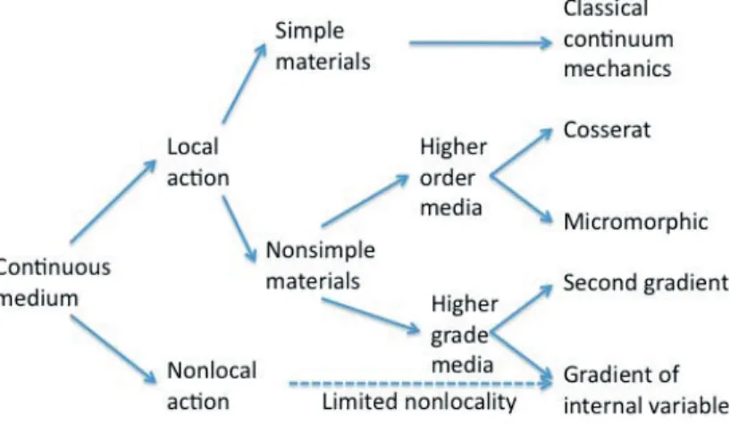
Figure 1 is a slight modification of the Forest classification of generalized continua in Forest (2013). They all, except the classical continuum mechanics approach, lead directly or indirectly to the introduction of a characteristic length scale. This length scale parameter is introduced in localization problems to eliminate their notorious mesh dependency (Baˇzant and Pijaudier-Cabot, 1988; Jir´asek and Rolshoven, 2003). Material models can be generalized to be able to capture the scale-dependent phenomena of localization problem by assuming that a material point can be deformable, as is the case with micromorphic continua and gradient theories. The local continuum can also be generalized to nonlocal mode by considering the constitutive equations as integral equations over a spatial neighborhood.
The micromorphic continuum was first introduced by the Cosserat brothers (Cosserat and Cosserat, 1909). Mindlin included second and third gradients of the displacement field in the context of elasticity (Mindlin, 1964). Additional degrees of freedom of the material points are used in the higher-order materials developed by Eringen (2012). A detailed derivation of the virtual power equation used for the micromorphic continuum is given in (Germain, 1973). Strain gradient plasticity theory was then proposed and improved by several authors to account for the size effect in the plastic regime (Aifantis, 1987; Fleck et al., 1997; Fleck and Hutchinson, 2001).
A generalized continuum framework based on the mathematical concept of fiber bundles was used by (Sansour
and Skatulla, 2012). The so-called computational continua (C2) approach was introduced and enhanced by Fish et
al. (2015) and Fish and Kuznetsov (2010), where no extra degrees of freedom are needed nor higher-order boundary conditions. The multiresolution continuum theory is a higher-order continuum theory (Liu et al., 2006, 2010; Tian et al., 2010) where additional kinematic variables supplementing the conventional macroscopic displacement field are added to account for the microscopic deformation across multiple scales. The MRCT is a multiscale finite element formulation that includes several other higher-order approaches as subset (Vernerey et al., 2007).
The nonlocal models account for possible interactions between a given point and surrounding material points (Baant and Lin, 1988). The size of this interaction domain is the characteristic length (Jir´asek, 2007). A nonlocal variable replaces the local softening variable in the classical damage model, leading to a nonlocal damage model. The nonlocal variable is obtained by weighted averaging of the softening variable over a spatial neighborhood of the material point, thus abandoning the local action principle (Jir´asek, 2007). The integral weighted averaging equation can be expanded in Taylor series to give the so-called explicit or implicit gradient methods (Peerlings et al., 1998). The mathematically equivalent implicit gradient method is implemented by adding the nonlocal variable as an additional degree of freedom in the finite element method (Engelen et al., 2003; Geers et al., 2003; Mediavilla et al., 2006). It is also worthwhile to mention here that in case of the strain hardening problem there is no reason to introduce a length scale to regularize the problem (Liu et al., 2014). Its primary purpose in the models compared in the current paper is to control localization behavior.
3. NONLOCAL MODEL IN DUCTILE FRACTURE 3.1 Coupling Plasticity and Damage
Plasticity is combined with damage in order to describe ductile fracture. Continuum mechanics can be used, provided an appropriate definition of average stress and strain for a representative volume element is used. The use of a contin-uum mechanics approach can be based on the hypothesis of strain equivalence (Simo and Ju, 1987). This leads to a definition of effective stress as a transformation of the Cauchy stress as
¯
σ = σ
1− ω (1)
Isotropic continuum damage is assumed when using Eq. (1). Physically, the damage parameterω can be interpreted
as the ratio of damaged surface area or volume over the total surface area or volume at a local material point. Usually
the material is assumed to have failed whenω reaches a critical damage ωc.
3.2 Local Damage Model for Ductile Failure
The strain equivalence formulation is combined with the assumption that damage affects elasticity, plasticity, or vis-coplasticity in the same way. This simplifies the modelling, as all deformation of a damaged material is represented in the constitutive law of the virgin material by replacing the stress by an effective stress. Notice that this effective
stress should not be confused with the von Mises’ effective stressσeintroduced later. In this formulation the free (or
state) variable of the thermodynamic process is the strain tensorε with the current damage represented by the internal
variableκ. The scalar damage variable is then a function of this internal variable as
ω = ω(κ) (2)
In ductile fracture, the damage state variable can be defined in the equivalent manner of the accumulated plastic strain
εp
e(Lemaitre and Desmorat, 2005). It is assumed that this variable can be used to characterize the progressive damage
for a general 3D stress state. A simple form of this local model is
ω = ω(εpe) (3)
3.3 Nonlocal Continuum
Nonlocal continuum formulations introduce a length scale by assuming that the state variables of the material con-stitutive equation depends not only on its local values, at say x, but also on the values of one or several of the state variables in a domain around x. This size of this domain allows a length scale parameter that is independent of the mesh size of the solution. This neighborhood effect can be accounted for by defining an integral of nonlocal state
variable vnlas introduced in (Baˇzant and Lin, 1988) as
vnl(x) =
∫
˜ Ω(x)
Φ(x′− x)vl(x′)dx′ (4)
In Eq. (4), vlrepresents the local state variable in the continuous mechanics model. Φ is a weighting function and ˜Ω is
the material volume around the point x in which Φ is not equal to zero. This integration volume usually extends over several finite elements.
3.4 Nonlocal Damage Model
The nonlocal integral Eq. (4) is applied to the damage variable Eq. (3), leading to
˜
Damage through the scalar damage variable ˜ω is coupled to plasticity through the effective Cauchy stress tensor ¯σ
calculated as
σ∇= (1− ˜ω) Ce: d (6)
whereσ is the Cauchy stress tensor, Ce is the elastic material fourth-order tensor, d is the elastic spatial velocity
gradient, and the right superscript∇ denotes any objective stress rate. Coupling of the damage variable to plasticity is
through the yield function F
F = σe
1− ˜ω− σy= ¯σe− σy (7)
The plastic flow rule is given by
˙¯εp= ˙λ ∂F
∂σ (8)
With the hardening variable taken as the accumulated plastic strain and its rate given by
˙¯εp= ˙λ (9)
Equation (9) is consistent with the loading–unloading condition by having
˙λ ≥ 0; F ≤ 0; ˙λF = 0 (10)
3.5 Numerical Implementation
This section summarizes the implementation of the nonlocal damage model in (Abiri and Lindgren, 2014). The in-crement in damage variablen+θi ˜εe
pin Eq. (5) is evaluated at time tn+θ, whereθ∈ [0, 1] and n is a time step counter.
This leads to n+θ i ˜ε p e= 1 Wi N∑gpi j = 1 j ̸= i αn+θij jεpewjJj+n+θi ε p ewiJi (11)
where wjis the weight of the numerical integration rule for the integration point and Jiis the Jacobian of the
isopara-metric mapping at this point. The modelθ = 0 in Eq. (11) corresponds to the explicit nonlocal update. The weight
factor Wiis introduced in order to normalize the total weight over the domain. It is computed as
Wi= N∑gpi
j=1
αijwjJj (12)
An example of the functionα is the Gaussian distribution function
αij = exp [ −∥xi− xj∥ 2l2 c ]2 (13)
whereα is the distance between integration points i and j. The interacting radius parameter lcabove gives the length
scale of the material deformation. Notice that αii = 1. The consistent tangent matrix Ct for use in the
Newton-Raphson equilibrium iteration scheme is calculated from slight perturbation ofσ∇in Eq. (6) at the current time step
to give
δσ∇= (1− ˜ω) δ ¯σ∇− δ ˜ωσ∇= Ct: δde (14)
For the explicit nonlocal update, the nonlocal tangent stiffness matrix is given as
Ct= (1− ˜ωi) Cep− d ˜ω di˜εpe σi⊗ ∂i˜εpe ∂εi (15)
4. MULTIRESOLUTION CONTINUUM THEORY 4.1 The MRCT Formulation
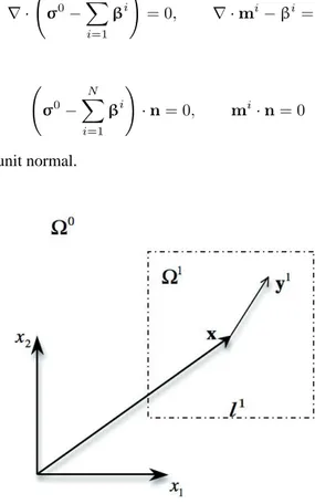
The starting point of the MRCT theory is the principle of virtual power. The internal virtual power is decomposed into a homogeneous and inhomogeneous part (McVeigh et al., 2006; Vernerey et al., 2009). We assume that during the deformation the rotation of the microdomain relative to macrodomain is ignored. The formulation leads, after some manipulations (Lindgren et al., 2011), to
δpint= δphomint + δp inh int = ∫ Ω ( σ0: δd0+ N ∑ i=1 ( βi: δ(di− d0)+ mi...δgid )) dΩ (16)
where d0is the macroscopic rate of deformation, and diis the microscopic strain rate measures. gi
dis the symmetric
part of gradient of microvelocity gradient gi.βiis the microstress and miis the microstress couple. Equation (16)
assumes a linear approximation of the variation of the velocity field liaround a material point x in each microdomain
i as shown in Fig. 2 for a microdomain. That is,
mli= li(x) + gi(x)· yi (17)
Using the principle of virtual power, integration by parts, and a divergence theorem, we have the equilibrium equation of the multiresolution continuum as
∇ · ( σ0− N ∑ i=1 βi ) = 0, ∇ · mi− βi= 0 (18)
with boundary conditions
( σ0− N ∑ i=1 βi ) · n = 0, mi· n = 0 (19)
where n is the outward pointing unit normal.
4.2 Constitutive Equations
We consider only one additional scale (N = 1) in Eqs. (18) and (19). The generalized objective stress rate and the generalized rate of deformation in the elastic regime are related by the multiresolution elasticity tensor as
σ 0∇ β1∇ m1∇ = C0σ C01β 00 0 0 C1m d 0 d1− d0 g1 d (20)
In Eq. (20), Cσis the same as the macroscopic elasticity tensor Ce. C1β and C
1
mare microscopic elasticity tensors
calculated as C1β= 1 Ω1 ∫ Ω1 mCadΩ = Ca, C1m= 1 Ω1 ∫ Ω1 mCa⊗ y ⊗ ydΩ = Ca⊗ (l1)2 12 I (21)
where I is the identity matrix and Cais taken as Ca = (1/10)Cσ(Vernerey et al., 2008). One of the key features of
the MRCT is that the length scale parameter l1has been directly incorporated as seen in Eq. (21), which is absent in
the conventional continuum mechanics method. In our current work, the subscale is considered to be pure elastic. A
J2-plasticity, hypoelastic plastic formulation with a damage model is used to model the material at the macroscopic
scale. Different damage criterions can be applied. The simple model in Eq. (3) has been used for comparison with the nonlocal damage model.
4.3 The Implicit MRCT 3D Element
There are nine degrees of freedom per node for the 3D MRCT element, three macroscopic velocities v0, and six rates
of deformation d1i at the subscale. The element interpolation of the nodal values is
ve= nnode∑ i=1 [ N0 0 0 N1 ] i [ v0 d1 ] i = Nv (22)
N0and N1indicate that we may use different functions to interpolate the nodal velocities than the microscopic
quan-tities. Likewise, we may use a different number of integration points during numerical integration. The model
imple-mentation and its algorithmic moduli for the macroscopic and microscopic scale are based on N1= N0as described
in (Qin et al., 2015). Thus the macroscopic velocity v0and microscopic rate of deformation d1are treated as
indepen-dent nodal degrees of freedom as described in Fish and Kuznetsov (2010) and by Shu et al. (1999). Therefore only C0
continuous interpolation is needed to ensure convergence of the finite element procedure.
5. NONLOCAL DAMAGE AND MRCT APPLICATION 5.1 Plane Strain Tensile Test
In this section, we compare the accuracy and robustness of the nonlocal damage model and MRCT theory shortly described in Sections 3 and 4. They are compared with respect to the prediction of the formation and evolution of the shear band of a tensile specimen containing an initial imperfection triggering localization. This test case is typically used to investigate shear band localization in the context of ductile failure (Baaser and Tvergaard, 2003; Drabek and B¨ohm, 2006; Enakoutsa et al., 2012). The nonlocal damage model and the MRCT will be referred to as NLD and MRCT, respectively.
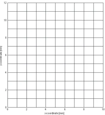
Figure 3 shows the 2D plain strain model used. Due to symmetry conditions of shape and deformation, one-fourth of the specimen is analyzed as shown. Its length is 10 mm and its height is 12 mm. We recall that numerical simulation with NLD is carried out in an implicit FEM code developed using Matlab (Lindgren, 2007). Discretization of the 2D elements is by four-node isoparametric plane strain elements as formulated and implemented for elastoplastic materials in Bonet and Wood (2008). A simplified variant of NLD, called an explicit nonlocal update, that only requires
FIG. 3: Geometry of the mesh used showing 120 four-node elements. A quarter of the specimen is modelled.
Sym-metry conditions are applied to the left (x = 0) and bottom (y = 0). The loading is a prescribed motion of the right side. The center of the specimen, x = 0, is initially 2% thinner than the ends, x = 10 mm.
an integration point data at the beginning of an increment is used, q = 0 in Eq. (11). The effect of this simplification was evaluated in Abiri and Lindgren (2014). This method is particularly simple to implement in commercial software. The MRCT element, MRCT, is implemented in the computer program FEAP, which was developed by R. L. Taylor
and co-workers (Zienkiewicz and Taylor, 2005). It is a 3D eight-node element with ¯B strain interpolations. Plane strain
conditions are enforced by appropriate restraints on the nodal displacements. The MRCT element has additional nodal degrees of freedom. The elastoplastic material properties are taken from (Simo, 1992). The flow stress of the material for the two methods is defined as
σy= σy0+ (σsat− σy0)
(
1− e−δεpe
)
+ Hlinεpe (23)
whereσy0= 450 MPa,σsat= 715 MPa, Hlin= 129.24 MPa, andδ = 16.93. A simple linear damage law is considered
for Eq. (3) in these investigations. Damage is a function of effective plastic strain given by
ω = min ( εp e− εf εr− εf , ωmax ) (24)
whereεfis the effective plastic strain at damage initiation andεrdenotes the value at fracture.ωmaxis an upper limit
applied in order to completely avoid loss of stiffness at that point. The damage parameters taken for Eq. (24) areεf=
0.05,εr= 0.3, andωmax= 0.9.
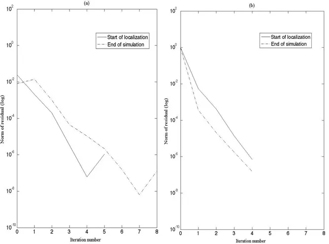
Figures 4 and 5 show the predictions of the two methods. The figures show that both methods are capable of obtaining convergent solutions when refining the mesh for this shear localization problem. Convergence plots for the nonlinear Newton-Raphson iterations of these implicit methods are shown in Fig. 6. The error norms at the end of simulation for the two methods are tabulated in Table 1. The global equilibrium iterative process required less than five
FIG. 4: Plot of force versus elongation using NLD with
length scale lc= 2.00 mm.
FIG. 5: Plot of force versus elongation using MRCT
with length scale l = 1.50 mm.
TABLE 1: Error norm in displacement
norms at the end of simulation using NLD with ∆t = 0.125 and MRCT with Dt = 0.02
NLD MRCT
Iteration error error
1 8.200E+00 1.000E+00
2 1.390E−02 3.663E−04
3 9.564E−04 2.097E−05
4 1.047E−05 1.731E−06
5 1.046E−05 1.519E−07
residual force. Both methods give second-order convergence at the start of localization and throughout the deformation process, except at the very end of the simulations. The shear band forms earlier in the NLD method than the MRCT method. As the shear band developed in both methods, the nonlinearity in their solutions increased significantly and the iterations and convergence becomes very difficult. The regularized plastic strain predictions are shown in Figs. 7– 12 and in Table 2 for 1920 elements with different length scale parameters. We define the shear band as the region
whereεp
e > 10%. Both methods can reproduce the same width of the shear band, however, at different values of the
length scale parameter. MRCT requires a somewhat smaller l to produce a shear band with the same width as for the NLD method. There is no simple relationship between length scale parameters and the damage properties used. A change in length scale will require a new calibration of damage parameter when fitting the model to a given case. This has also been shown in damage modelling of quasibrittle materials (Zreid and Kaliske, 2014). The length scale parameters are also known to depend on strain rates, temperature, and failure mechanism (Abu Al-Rub and Voyiadjis, 2004). We also note that both methods require a fine mesh to correctly predict the localized deformation. The localized zone (i.e., the length scale) cannot be smaller than the element size in the NLD method. This is a fact for all nonlocal models. The MRCT method requires a fine mesh that must resolve the chosen length scale.
6. CONCLUDING REMARKS
A nonlocal damage approach is compared with a MRCT element with respect to their use in localization problems. Both methods have been shown in Abiri and Lindgren (2014) and Qin et al. (2015) to yield mesh-independent results.
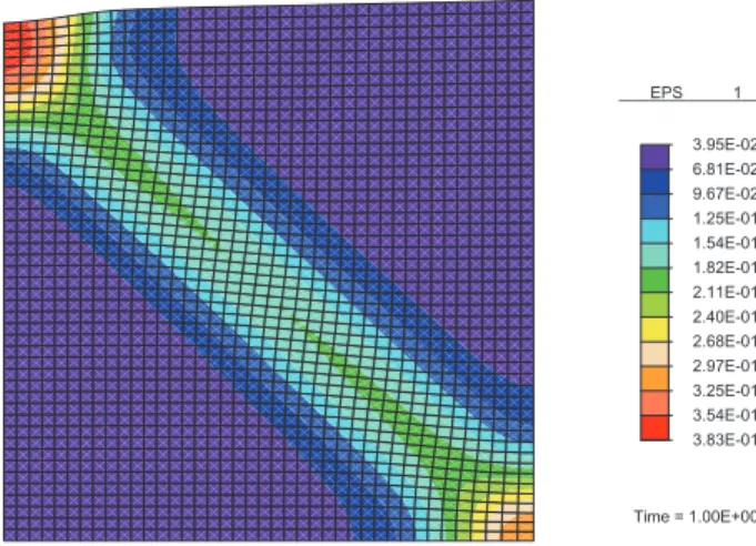
6.81E-02 9.67E-02 1.25E-01 1.54E-01 1.82E-01 2.11E-01 2.40E-01 2.68E-01 2.97E-01 3.25E-01 3.54E-01 3.95E-02 3.83E-01 _________________ EPS 1 Time = 1.00E+00
6.04E-02 7.97E-02 9.90E-02 1.18E-01 1.38E-01 1.57E-01 1.76E-01 1.96E-01 2.15E-01 2.34E-01 2.54E-01 4.10E-02 2.73E-01 _________________ EPS 1 Time = 1.00E+00
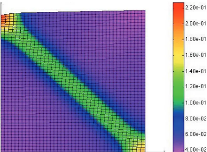
FIG. 8: Plot of effective plastic with 1920 elements at end of simulation using MRCT, l = 1.00 mm.
5.58E-02 6.89E-02 8.20E-02 9.50E-02 1.08E-01 1.21E-01 1.34E-01 1.47E-01 1.60E-01 1.73E-01 1.87E-01 4.28E-02 2.00E-01 _________________ EPS 1 Time = 1.00E+00
FIG. 9: Plot of effective plastic with 1920 elements at end of simulation using MRCT, l = 1.50 mm.
FIG. 11: Plot of effective plastic with 1920 elements at end of simulation using NLD, lc= 1.50 mm.
FIG. 12: Plot of effective plastic with 1920 elements at end of simulation using NLD, lc= 2.00 mm.
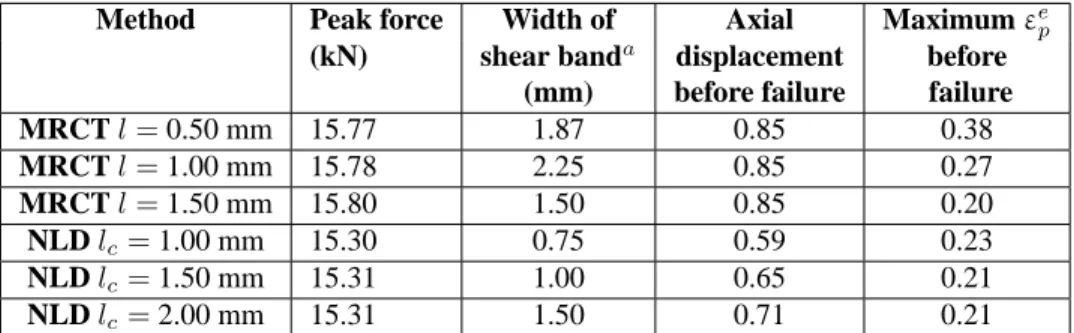
TABLE 2: Investigation of length scale effects on shear band using 1920 elements
Method Peak force Width of Axial Maximumεep
(kN) shear banda displacement before
(mm) before failure failure
MRCT l = 0.50 mm 15.77 1.87 0.85 0.38 MRCT l = 1.00 mm 15.78 2.25 0.85 0.27 MRCT l = 1.50 mm 15.80 1.50 0.85 0.20 NLD lc= 1.00 mm 15.30 0.75 0.59 0.23 NLD lc= 1.50 mm 15.31 1.00 0.65 0.21 NLD lc= 2.00 mm 15.31 1.50 0.71 0.21
Thus both approaches can be used for localization problems. The MRCT method is very general and has been used in quite advanced studies of fracturing processes (Tian et al., 2010; Tang et al., 2013). However, the comparison shows that the nonlocal damage model has several advantages for the current scope, use in manufacturing simulations, particularly in machining:
• It requires less computer time, as it has no additional nodal degrees of freedom as the MRCT element has.
The analysis based on the MRCT element still requires about the same amount of elements, as the mesh must resolve the selected length scale. Its length scale cannot be made large enough to compensate for this.
• The MRCT theory has higher-order boundary conditions that complicate the modelling.
• Another, very important issue is that the explicit nonlocal update, i.e., use of q = 0 in Eq. (11), makes it simple
to implement the NLD approach via user routines in commercial finite element packages. The effect of this simplification was evaluated in Abiri and Lindgren (2014).
ACKNOWLEDGMENTS
The authors gratefully acknowledge the financial support of the Centre of High Performance Steels (CHS) at Lule˚a University of Technology, National Mathematical Centre, Abuja and Tetfund, Nigeria. Funding from the strategic innovation programme LIGHTer provided by Vinnova is acknowledged.
REFERENCES
Abiri, O. and Lindgren, L., Non-local damage models in manufacturing simulations, Eur. J. Mech. A. Solids, vol. 49, pp. 548–560, 2014.
Abu Al-Rub, R. K. and Voyiadjis, G. Z., Analytical and experimental determination of the material intrinsic length scale of strain gradient plasticity theory from micro- and nano-indentation experiments, Int. J. Plast., vol. 20, no. 6, pp. 1139–1182, 2004. Aifantis, E. C., The physics of plastic deformation, Int. J. Plast., vol. 3, no. 3, p. 211, 1987.
Baaser, H. and Tvergaard, V., A new algorithmic approach treating nonlocal effects at finite rate-independent deformation using the Rousselier damage model, Comput. Methods Appl. Mech. Eng., vol. 192, no. 1, pp. 107–124, 2003.
Baˇzant, Z. and Pijaudier-Cabot, G., Nonlocal continuum damage, localization instability, and convergence, J. Appl. Mech., vol. 55, no. 2, pp. 287–293, 1988.
Baˇzant, Z. and Lin, F., Nonlocal yield limit degradation, Int. J. Numer. Methods Eng., vol. 26, no. 8, pp. 1805–1823, 1988. Baˇzant, Z. and Jir´asek, M., Nonlocal integral formulations of plasticity and damage: Survey of progress, J. Eng. Mech., vol. 128,
no. 11, pp. 1119–1149, 2002.
Bonet, J. and Wood, R. D., Nonlinear Continuum Mechanics for Finite Element Analysis, Cambridge University Press, New York, 2008.
Cosserat, E. and Cosserat, F., Th´eorie des Corps D´eformables, Librairie Scientifique A, Paris, France, 1909.
Drabek, T. and B¨ohm, H. J., Micromechanical finite element analysis of metal matrix composites using nonlocal ductile failure models, Comput. Mater. Sci., vol. 37, no. 1-2, pp. 29–36, 2006.
Enakoutsa, K., Ahad, F. R., Solanki, K. N., Tjiptowidjojo, Y., and Bammann, D. J., Using damage delocalization to model local-ization phenomena in Bammann-Chiesa-Johnson metals, J. Eng. Mater. Technol., vol. 134, no. 4, p. 041014, 2012.
Engelen, R. A., Geers, M. G., and Baaijens, F., Nonlocal implicit gradient-enhanced elasto-plasticity for the modelling of softening behaviour, Int. J. Plast., vol. 19, no. 4, pp. 403–433, 2003.
Eringen, A. C., Microcontinuum Field Theories: I. Foundations and Solids, Springer Science and Business Media, Berlin, 2012. Fish, J. and Kuznetsov, S., Computational continua, Int. J. Numer. Methods Eng., vol. 84, no. 7, pp. 774–802, 2010.
Fish, J., Filonova, V., and Fafalis, D., Computational continua revisited, Int. J. Numer. Methods Eng., vol. 102, no. 3-4, pp. 332–378, 2015.
Fleck, N. A. and Hutchinson, J. W., A reformulation of strain gradient plasticity, J. Mech. Phys. Solids, vol. 49, no. 10, pp. 2245– 2271, 2001.
Fleck, N. A., Hutchinson, J. W., and Wuodore, Y., Strain gradient plasticity, Adv. Appl. Mech., vol. 33, pp. 296–361, 1997. Forest, S., Micromorphic Media: Generalized Continua from the Theory to Engineering Applications, pp. 249–300, Springer, New
York, 2013.
Geers, M., Ubachs, R., and Engelen, R., Strongly non-local gradient-enhanced finite strain elastoplasticity, Int. J. Numer. Methods Eng., vol. 56. no. 14, pp. 2039–2068, 2003.
Germain, P., The method of virtual power in continuum mechanics, Part 2: Microstructure, SIAM J. Appl. Math., vol. 25, no. 3, pp. 556–575, 1973.
Jir´asek, M., Nonlocal damage mechanics, Revue Europ´eenne De G´enie Civil, vol. 11, pp. 993–1021, 2007.
Jir´asek, M. and Rolshoven, S., Comparison of integral-type nonlocal plasticity models for strain-softening materials, Int. J. Eng. Sci., vol. 41, no. 13-14, pp. 1553–1602, 2003.
Lemaitre, J. and Desmorat, R., Engineering Damage Mechanics, Springer-Verlag, Berlin/Vienna/New York, 2005.
Lindgren, L., Computational Welding Mechanics: Thermomechanical and Microstructructural Simulations, CRC Press, Boca Ra-ton, FL, 2007.
Lindgren, L., Qin, H., Liu, H., and Tang, S., Simplified multiscale resolution continuum theory for elastic material with damage, The 6th Intl. Conf. of Computational Plasticity, (COMPLAS XI), E. Onate and D. R. J. Owen, Eds., Barcelona, Spain, 2011. Liu, W., Karpov, E., and Park, H., Nano Mechanics and Materials: Theory, Multiscale Methods and Applications, John Wiley &
Sons, 2006.
Liu, W. K., Qian, D., Gonella, S., Li, S., Chen, W., and Chirputkar, S., Multiscale methods for mechanical science of complex materials: Bridging from quantum to stochastic multiresolution continuum, Int. J. Numer. Methods Eng., vol. 83, no. 8-9, pp. 1039–1080, 2010.
Liu, Y., Filonova, V., Hu, N., Yuan, Z., Fish, J., Yuan, Z., and Belytschko, T., A regularized phenomenological multiscale damage model, Int. J. Numer. Methods Eng., vol. 99, no. 12, pp. 867–887, 2014.
McVeigh, C., Vernerey, F., Liu, W. K., and Cate Brinson, L., Multiresolution analysis for material design, Comput. Methods Appl. Mech. Eng., vol. 195, no. 37, pp. 5053–5076, 2006.
Mediavilla, J., Peerlings, R., and Geers, M., A nonlocal triaxiality-dependent ductile damage model for finite strain plasticity, Comput. Methods Appl. Mech. Eng., vol. 195, no. 33, pp. 4617–4634, 2006.
Mindlin, R. D., Micro-structure in linear elasticity, Archive for Rational Mechanics and Analysis, vol. 16, no. 1, p. 51, 1964. Nakayama, K. and Tamura, K., Size effect in metal-cutting force, J. Manuf. Sci. Eng., vol. 90, no. 1, pp. 119–126, 1968.
Peerlings, R., De Borst, R., Brekelmans, W., and Geers, M., Gradient-enhanced damage modelling of concrete fracture, Mech. Cohesive-Frict. Mater., vol. 3, no. 4, pp. 323–342, 1998.
Qin, H., Lindgren, L., Liu, W. K., and Smith, J., Implicit finite element formulation of multiresolution continuum theory, Comput. Methods Appl. Mech. Eng., vol. 293, pp. 114–130, 2015.
Sansour, C. and Skatulla, S., Generalized Continua and Dislocation Theory: Theoretical Concepts, Computational Methods, and Experimental Verification, Springer Science and Business Media, Berlin, 2012.
Shu, J. Y., King, W. E., and Fleck, N. A., Finite elements for materials with strain gradient effects, Int. J. Numer. Methods Eng., vol. 44, no. 3, pp. 373–391, 1999.
Simo, J. C., Algorithms for static and dynamic multiplicative plasticity that preserve the classical return mapping schemes of the infinitesimal theory, Comput. Methods Appl. Mech. Eng., vol. 99, no. 1, p. 61, 1992.
Simo, J. C. and Ju, J. W., Strain- and stress-based continuum damage models—I. Formulation, Int. J. Solids Struct., vol. 23, no. 7, pp. 821–840, 1987.
Svoboda, A., Wedberg, D., and Lindgren, L., Simulation of metal cutting using a physically based plasticity model, Modell. Simul. Mater. Sci. Eng., vol. 18, no. 7, p. 075005, 2010.
Tang, S., Kopacz, A. M., Olson, G. B., and Liu, W. K., Three-dimensional ductile fracture analysis with a hybrid multiresolution approach and microtomography, J. Mech. Phys. Solids, vol. 61, no. 11, pp. 2108–2124, 2013.
Tian, R., Chan, S., Tang, S., Kopacz, A. M., Wang, J. S., Jou, H. J., Siad, L., Lindgren, L. E., Olson, G. B., and Liu, W. K., A multiresolution continuum simulation of the ductile fracture process, J. Mech. Phys. Solids, vol. 58, no. 10, pp. 1681–1700, 2010.
Vaz, Jr., M., Owen, D., Kalhori, V., Lundblad, M., and Lindgren, L., Modelling and simulation of machining processes, Arch. Comput. Methods Eng., vol. 14, no. 2, pp. 173–204, 2007.
Vernerey, F. J., Liu, W. K., and Moran, B., Multi-scale micromorphic theory for hierarchical materials, J. Mech. Phys. Solids, vol. 55, no. 12, pp. 2603–2651, 2007.
Vernerey, F. J., Liu, W. K., Moran, B., and Olson, G., A micromorphic model for the multiple scale failure of heterogeneous materials, J. Mech. Phys. Solids, vol. 56, no. 4, pp. 1320–1347, 2008.
Vernerey, F. J., Liu, W. K., Moran, B., and Olson, G., Multi-length scale micromorphic process zone model, Comput. Mech., vol. 44, no. 3, pp. 433–445, 2009.
Wu, T., Coret, M., and Combescure, A., Strain localisation and damage measurement by full 3D digital image correlation: Appli-cation to 15-5PH stainless steel, Strain, vol. 47, no. 1, pp. 49–61, 2011.
Zienkiewicz, O. C. and Taylor, R. L., The Finite Element Method for Solid and Structural Mechanics, Butterworth-Heinemann, Oxford, UK, 2005.
Zreid, I. and Kaliske, M., Regularization of microplane damage models using an implicit gradient enhancement, Int. J. Solids Struct., vol. 51, no. 19, pp. 3480–3489, 2014.