A 512-point 8-parallel pipelined feedforward FFT
for WPAN
Tanvir Ahmed, Mario Garrido, Member, IEEE, and Oscar Gustafsson, Senior Member, IEEE
Department of Electrical Engineering, Link¨oping UniversitySE-581 83 Link¨oping, Sweden
E-mail: tanah449@student.liu.se, mariog@isy.liu.se, oscarg@isy.liu.se
Abstract—This paper presents a 512-point feedforward FFT architecture for wireless personal area network (WPAN). The architecture processes a continuous flow of 8 samples in parallel, leading to a throughput of 2.64 GSamples/s. The FFT is computed in three stages that use radix-8 butterflies. This radix reduces significantly the number of rotators with respect to previous approaches based on radix-2. Besides, the proposed architecture uses the minimum memory that is required for a 512-point 8-parallel FFT.
Experimental results show that besides its high throughput, the design is efficient in area and power consumption, improving the results of previous approaches. Specifically, for a wordlength of 16 bits, the proposed design consumes 61.5 mW and its area is 1.43 mm2.
Index Terms—Fast Fourier Transform (FFT), Radix-8, Multi-path Delay Commutator (MDC), Pipelined Architecture, Wireless Personal Area Network (WPAN).
I. INTRODUCTION
In the last years, new standards that demand very high performance have been released. This includes standards such as IEEE 802.11a/b/g/n, IEEE 802.15 and IEEE 802.16j/k/h for ultra wide band (UWB), wireless personal area network (WPAN) and Wi-Max, respectively.
In IEEE 802.15.3c, HSIPHY is applied to wireless con-nectivity and uses orthogonal frequency division multiplexing (OFDM) to overcome the multipath fading effect. The fast Fourier transform (FFT) is a key component for the implemen-tation of OFDM. To meet the requirements of the standard, a very high-throughput FFT must be implemented. Specifically, a 512-point FFT that processes 2640 MSamples/s [1] is required.
Due to this increasing demand on signal processing capa-bilities, much research on pipelined FFT processors has been done in the last years and high-throughput architecture have been proposed [2]–[9]. In previous ultra wideband (UWB) systems, a 128-point FFT processor is used with a throughput rate of 409.6 MSamples/s [9]. For WPAN, a 2048-point FFT that processes 2.4 GSamples/s was presented in [2], where 8-parallel data were used to achieve this high throughput; an 8-parallel radix-16+2 iterative architecture was proposed in [3] and a 4-parallel mixed-radix Multi-path Delay Feedback (MDF) architecture was proposed in [4].
This paper presents a 512-point 8-parallel FFT for WPAN. It consists of a feedfoward (FF) architecture, also called
Multi-path Delay Commutator (MDC) [10], with three radix-8 stages. This structure reduces the number of rotators with respect to designs based on radix-2 [11], [12]. Besides, pre-vious 8-parallel radix-8 feedforward FFTs [5] used a dou-ble buffering strategy [13], which increases significantly the required amount of memory. Conversely, in the proposed architecture the data shuffling is carried out by shuffling structures that consist of buffers and multiplexers, leading to a total memory size of 504. This is, indeed, the minimum memory required for a 512-point 8-parallel FFT [8]. Finally, experimental results reveal that the proposed design requires less area and consumes less power than previous approaches in the literature.
The paper is organized as follows: the following Section re-views the radix-8 algorithm. Section III presents the proposed architecture and compares it to previous architectures for the computation of a 512-point 8-parallel FFT. Several consid-erations about the hardware implementation are discussed in Section IV and experimental results are shown in Section V. Finally, conclusions are drawn in Section VI.
II. THERADIX-8 ALGORITHM
The N -point DFT of an input sequence x[n] is defined as:
X[k] =
N∑−1
n=0
x [n] WNnk, k = 0, 1, . . . , N− 1 (1) where WNnk= e−j2πNnk.
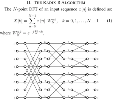
Fig. 1. Flow graph of an 8-point FFT.
In order to compute the DFT efficiently, the FFT based on the Cooley-Tukey algorithm [14] is most times used, which
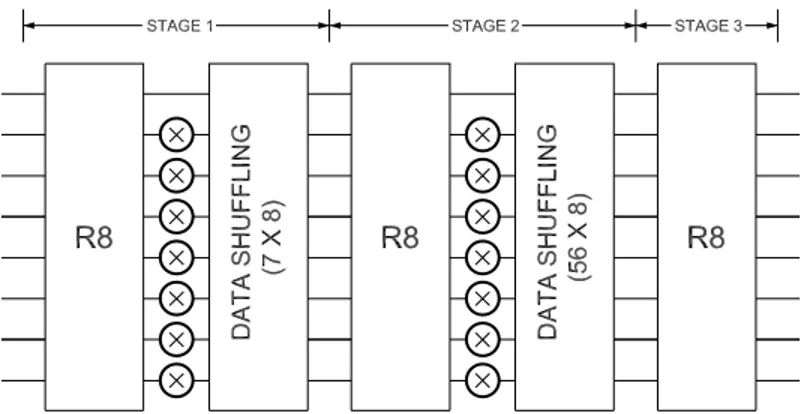
Fig. 2. Proposed 512-point 8-parallel radix-8 FFT architecture.
reduces the number of operations from O(N2) for the DFT to O(N log N ) for the FFT. According to this, the FFT is calculated in a series of n = logrN stages, where r is the radix of the FFT. Each of these stages calculates an r-point FFT as well as rotations of the data.
For radix-8 the number of stages is log8N and each stages calculates an 8-point FFT, whose flow graph for the decimation in frequency (DIF) decomposition [15] is shown in Figure 1. A further explanation on the mathematical derivation of the radix-8 algorithm can be found in [16].
In Fig. 1 the numbers at the input represent the index of the input sequence, whereas those at the output are the frequen-cies, k, of the output signal X[k]. Besides, each number, ϕ, in between the stages indicates a rotation by:
WNϕ = e−j2πNϕ (2)
As a consequence, samples for which ϕ = 0 do not need to be rotated, whereas ϕ = 2 represents a rotation by −j. This is a trivial rotation and it can be implemented in hardware at no cost [6].
III. PROPOSEDARCHITECTURE
The proposed 512-point 8-parallel radix-8 pipelined feedfor-ward FFT architecture is depicted in Figure 2. It can process a continuous flow of 8 samples in parallel per clock cycle, which allows for achieving very high throughputs.
The proposed architecture consists of three stages. At each stage a radix-8 butterfly is calculated. As the architecture receives 8 samples in parallel, the structure of the butterfly is a direct mapping of the flow graph of an 8-point FFT, which is shown in Fig. 1. Thus, each butterfly contains 24 complex adders and two complex constant multipliers for ϕ = 1 and
ϕ = 3.
The first two stages also include rotators, leading to a total of 14 complex multipliers for the whole FFT. For each rotator, the architecture uses a ROM to store the coefficients. Each of the seven memories at the first stage stores 64 coefficients, whereas at the second one they store 8 coefficients.
Besides, circuits for data management are necessary be-tween consecutive stages. The basic shuffling structure is depicted in Figure 3. This circuit has already been used in
Fig. 3. Basic circuit for data shuffling.
Fig. 4. Shuffling circuit for the first stage of the FFT.
previous pipelined FFT architectures [6], [10], and consists of two multiplexers and input and output buffers. The input and output buffer lengths, L, vary with different stages of the architecture. When the control signal is 0, the input samples are stored in the buffers, wheras samples in the output buffer are replaced by those in the input buffer when the control signal is 1.
This basic circuit is used to carry out the data shuffling at the two first stages of the proposed FFT architecture. For the first stage of the FFT, the circuit that carries out the data shuffling is depicted in Figure 4. It consists of three stages of basic shuffling circuits with four of them in parallel at each stage. As shown in the figure, the lengths of the buffers are 1, 2 and 4 for the first, second and third stages, respectively. This leads to a total memory of 7× 8, as shown in Figure 2. An analogous circuit is used for the data shuffling of the second stage of the FFT. In this case, the input and output buffer lengths are 32, 16 and 8, being the total memory 7× 56.
Finally, the control of the architecture is very simple. It uses a six-bit counter to control the shuffling circuits as well as to
obtain the coefficients for the rotators. As the multiplexers commute every L clock cycles and L is a power of two, the control signals are directly obtained from the bits of the counter. Likewise, the addresses of the ROMs are directly obtained from the bits of the counter. The specific bit used for each signal in the architecture depends on the period of the control signal. The MSB of the counter has been mapped to those control signals that have a period of 64 clock cycles, whereas the LSB of the counter has been mapped to those control signals that have a period of 2 clock cycles.
Table I compares the proposed architecture with previous approaches for the computation of a 512-point 8-parallel FFT. The table includes the number of complex rotators, adders and total sample memory. The number of constant rotators is indicated in parenthesis.
In the table it can be observed that pipelined architectures that use radix-8 require less rotators than those based on radix-2. Besides, compared to previous 8-parallel radix-8 feed-forward FFT architectures [5], the proposed design reduces considerably the memory requirements. This is due to the fact that in [5] a double buffering technique [13] is used, whereas the proposed approach carries out the permutations without duplicating the memory.
IV. HARDWARE IMPLEMENTATION
The FFT has been described in VHDL. On the one hand, as different applications may require different bit error rate, the proposed design is parameterizable in wordlength. On the other hand, different techniques have been taken into consideration for reducing the the power and the area of the FFT. Those techniques are frequency scaling, voltage scaling and optimization of the architecture, as explained next.
The dynamic power of any circuit can be calculated by [17]:
Pdynamic= 1
2αfclkCLV 2
dd (3)
where α is the switching activity, fclkis the clock frequency,
CL is the load capacitance and Vdd is the supply voltage. Initially, the FFT was synthesized for 380 MHz clock and 1.2 V. As the required throughput of the FFT is 2.64 GS/s and 8 parallel data have been used, a clock frequency 330 MHz clock is enough to achieve this throughput. This reduction in frequency not only reduces the dynamic power, but also increases the slack time, which allows for reducing the supply voltage. As a result, the voltage has been reduced from 1.2 V to 0.8 V. Thus, the combination of the frequency and supply voltage scalings reduces the power consumption a factor 0.38 = 1− (330/380) × (0.8/1.2)2, which represents savings in power consumption larger than 60%.
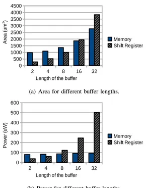
Besides, the design of the FFT architecture has been carried out focusing on reducing the area and power consuption. For the implementation of the buffers, both memories and shift registers have been considered. Figure 5 shows the area and power consumption of buffers implemented using shift registers and memories. On one hand, the switching activity increases with the length of the buffers for shift registers
(a) Area for different buffer lengths.
(b) Power for different buffer lengths.
Fig. 5. Area and power consumption of buffers implemented using shift registers and memories.
and causes more power consumption. On the other hand, the switching activity remains constant for the memories, as the read and write pointer change on every clock cycle. As a result, for short buffers shift registers require less area and consume less power. Conversely, for buffer lengths over 8 it is prefereable to use memories. According to this, shift registers have been used for short buffers in the FFT, whereas memories have been used for long buffers.
V. EXPERIMENTALRESULT
The FFT has been implemented using standard cells and the 65 nm CORE65LPSVT libray. The design has been synthesized by Design compiler and Nanosim has been used to calculate the power consumption. Table II compares the results of the proposed approach to other FFT architectures for WPAN in the literature. For the proposed approach, results for 8, 12 and 16 bits are included. As the designs in the table use different technologies, the power consumption and area have been normalized [18], [19] according to:
Normalized Area = Area
(Tech. / 65 nm)2 (4)
Normalized Power = Power consumption
(Tech. / 65 nm)× (VDD/0.8)2 (5) Table II shows that the proposed approach achieves higher throughput and requires lower area and power consumption that previous approaches in the literature. Specifically, for a 512-point 12-bit FFT, the proposed approaches obtains an improvement of 12 % in power consumption and 31 % in area with respect to previous approaches [3].
TABLE I
COMPARISON OF ARCHITECTURES FOR THE COMPUTATION OF A512-POINT8-PARALLELFFT.
PIPELINED AREA PERFORMANCE
ARCHITECTURE Complex Complex Complex Latency Throughput Type Radix Rotators Adders Sample Memory (cycles) (samples/cycle)
FF (MDC) Radix-8, [5] 14(6) 72 1170 146 8 FF (MDC) Radix-2, [11] 28 72 504 63 8 FB (MDF) Radix-2, [12] 28 144 504 63 8 Iterative Radix-16 + 2, [3] 32 256 1024 71 8 FF (MDC) Proposed, radix-8 14(6) 72 504 63 8 TABLE II
COMPARISON OFVARIOUSFFTFORWPANAPPLICATION
PREVIOUS APPROACHES PROPOSED APPROACH Iterative FB (MDF) FB (MDF) FF (MDC) PARAMETERS [3] [4] [2] 8-bit 12-bit 16-bit
FFT size (N) 512 2048 2048 512 512 512 Parallel samples (P) 8 4 8 8 8 8 Radix (r) 16 + 2 Mixed 2 8 8 8 Wordlength (bits) 12 9 9 8 12 16 Process (nm) 90 90 90 65 65 65 Voltage (V) 1 1 1 0.8 0.8 0.8 Clock (MHz) 324 300 300 330 330 330 Throughput (GS/s) 2.59 1.2 2.4 2.64 2.64 2.64 Area (mm2) 2.46 0.97 1.16 0.39 0.88 1.43 Normalized Area (mm2) 1.28 0.5 0.6 0.39 0.88 1.43 Power (mW) 103.5 117 159 38.49 42.04 61.51 Normalized Power (mW) 47.84 54.08 73.49 38.49 42.04 61.51 VI. CONCLUSIONS
In this paper, a 512 point and 2.64 GS/s throughput FFT processor for IEEE 802.15.3c has been proposed. The FFT is paramatrazible in wordlength, which can be selected according to the application. Besides, the number of complex multi-plication, complex addition and buffers have been reduced significantly by adopting 8 parallel and radix-8 feedforward architecture for the FFT. Finally, Experimental results show that besides its high throughput, the design is efficient in area and power consumption, improving the results of previous approaches.
REFERENCES
[1] “IEEE Std 802.15.3c-2009, part 15.3: Wireless Medium Access Control (MAC) and Physical Layer (PHY) Specifications for High Rate Wireless Personal Area Networks (WPANs),” 2009.
[2] S.-N. Tang, J.-W. Tsai, and T.-Y. Chang, “A 2.4-GS/s FFT processor for OFDM-based WPAN applications,” IEEE Trans. Circuits Syst. II, vol. 57, no. 6, pp. 451 –455, Jun. 2010.
[3] S.-J. Huang and S.-G. Chen, “A green FFT processor with 2.5-GS/s for IEEE 802.15.3c (WPANs),” in Proc. Int. Conf. Green Circuits Syst., Jun. 2010, pp. 9–13.
[4] Y. Chen, Y.-C. Tsao, Y.-W. Lin, C.-H. Lin, and C.-Y. Lee, “An indexed-scaling pipelined FFT processor for OFDM-based WPAN applications,”
IEEE Trans. Circuits Syst. II, vol. 55, no. 2, pp. 146 –150, Feb. 2008.
[5] M. S´anchez, M. Garrido, M. L´opez, and J. Grajal, “Implementing FFT-based digital channelized receivers on FPGA platforms,” IEEE Trans.
Aerosp. Electron. Syst., vol. 44, no. 4, pp. 1567–1585, Oct. 2008.
[6] M. Garrido, K. K. Parhi, and J. Grajal, “A pipelined FFT architecture for real-valued signals,” IEEE Trans. Circuits Syst. I, vol. 56, no. 12, pp. 2634–2643, Dec. 2009.
[7] M. Garrido, J. Grajal, M. S´anchez, and O. Gustafsson, “Pipelined radix-2kfeedforward FFT architectures,” IEEE Trans. VLSI Syst., Accepted for publication.
[8] M. Garrido, “Efficient hardware architectures for the computation of the FFT and other related signal processing algorithms in real time,” Ph.D. dissertation, Universidad Polit´ecnica de Madrid, 2009.
[9] Y.-W. Lin, H.-Y. Liu, and C.-Y. Lee, “A 1-GS/s FFT/IFFT processor for UWB applications,” IEEE J. Solid-State Circuits, vol. 40, no. 8, pp. 1726 – 1735, Aug. 2005.
[10] S. He and M. Torkelson, “Design and implementation of a 1024-point pipeline FFT processor,” in Proc. IEEE Custom Integrated Circuits
Conf., May 1998, pp. 131–134.
[11] J. Johnston, “Parallel pipeline fast fourier transformer,” in IEE Proc. F
Comm. Radar Signal Process., vol. 130, no. 6, Oct. 1983, pp. 564–572.
[12] E. Wold and A. Despain, “Pipeline and parallel-pipeline FFT processors for VLSI implementations,” IEEE Trans. Comput., no. 5, pp. 414–426, May 1984.
[13] Y.-N. Chang, “An efficient VLSI architecture for normal I/O order pipeline FFT design,” IEEE Trans. Circuits Syst. II, vol. 55, no. 12, pp. 1234–1238, Dec. 2008.
[14] J. Cooley and J. Tukey, “An algorithm for the machine calculation of complex Fourier series,” Math. Comput., vol. 19, pp. 297–301, 1965. [15] A.V.Oppenheim and R.W.Schafer, Discrete-Time Signal Processing.
Prentice Hall, 1989.
[16] S. Bouguezel, M. Ahmad, and M. Swamy, “Improved 4 and radix-8 FFT algorithms,” in Proc. IEEE Symp. Circuits Syst, vol. 3, May 2004, pp. III – 561–4.
[17] A. Chandrakasan and R. Brodersen, “Minimizing power consumption in digital CMOS circuits,” Proc. IEEE, vol. 83, no. 4, pp. 498–523, Apr. 1995.
[18] Y. Chen, Y. Lin, Y. Tsao, and C. Lee, “A 2.4-GSample/s DVFS FFT processor for MIMO OFDM communication systems,” IEEE J.
Solid-State Circuits, vol. 43, no. 5, pp. 1260–1273, May 2008.
[19] B. Baas, “A low-power, high-performance, 1024-point FFT processor,”