VACUUM INFUSION OF NANOCELLULOSE NETWORKS OF
DIFFERENT POROSITY
Yvonne Aitomäki1, Sergio Moreno-Rodriguez1, Staffan Lundström2 and Kristiina Oksman1 1 Division of Materials Science, Composite Centre Sweden,
Luleå University of Technology 971 87 Luleå, Sweden Email: yvonne.aitomaki@ltu.se, web page: http://www.ltu.se
2Division of Fluid and Experimental Mechanics, Luleå University of Technology 971 87 Luleå, Sweden
Keywords: cellulose fibers, permeability characterization, vacuum infusion ABSTRACT
Cellulose nanofibres (CNF) have shown good potential as sustainable, biobased reinforcing materials in polymer composites. Addressing issues around the processing of these composites is an important part of establishing their use in different applications. Here, CNF networks of different porosity are made from nanofibrillated hardwood kraft pulp with the aim of increasing the impregnation of the CNF networks and to allow vacuum infusion to be used. Two different vacuum infusion strategies: in-plane and out of plane were used to infuse the CNF networks with a low viscosity epoxy. The permeability, morphology and mechanical properties of the dry networks and the resulting nanocomposites were investigated and compared to a micro-fibre based network. Using the out-of-plane permeability measurements and Darcy’s law, the fill-time was calculated and showed that the CNF network with 40% porosity had the lowest fill-time when an out-of-plane impregnation strategy is used. However this exceeded the gel-time of the epoxy system. In experiments, the resin reached the other side of the network but low transparency indicated that wetting was poor. The dry CNF preforms showed a very strong dependence on the porosity with both modulus and strength increasing rapidly at low porosity. Interestingly, the composite based on the 60% porosity network showed good wetting particularly with the in-plane infusion strategy, exhibiting a much more brittle fracture and a high yield strength. This shows that in CNF composites produced by VI, lowering the fibre volume content of the CNF composites gives better impregnation resulting in a lower ultimate strength but higher yield strength and no loss in modulus.
1 INTRODUCTION
Cellulose nanofibres from plant cells walls (CNF) have shown good potential as sustainable, biobased reinforcing materials in polymer composites [1,2]. These nanofibres have high stiffness, strength and high aspect ratio and hence can be used to good effect in reinforcing polymers. Addressing issues around the processing of these nanocomposites is an important part of establishing their use in different applications [1]. In addition, based on a review of current composites based on CNF, for these materials to have mechanical properties higher than a biobased matrix, fibre volume fractions above 30% are required [3].
In short-fibre composites, the effect of the matrix is to allow stress to be transferred between fibres. Similarly, in the case of the nanocomposites, it is thought that the matrix can be used to enhance the existing bonds between the nanofibres, thus increasing stress transfer as well as improving factors such as the resistance to moisture of the composites. For this to be achieved, good impregnation and consolidation of the nanocomposites is necessary. Liquid composite molding processes, such as vacuum infusion, are based on impregnating dry preforms with low viscosity resins and so are potentially suitable processes for manufacturing nanocomposites from dry networks of CNF. However one of the fundamental characteristics of networks of CNF with good mechanical properties [2] is their high density, which presents a challenge to their impregnation with resin.
CNF based composites with some of the highest mechanical properties have been achieved using high volume fraction CNF networks with a long impregnation period of up to 106 hours [2,4], where
the CNF network is submersed in a bath of melamine formaldehyde or phenol formaldehyde and a vacuum pressure applied to force the release of remaining air, after which the network remain submerged at atmospheric pressure. Although this process produces composites with high mechanical properties (17 GPa and 121 MPa for stiffness and strength, respectively with 9%wt melamine formadehyde [4]), the process is not efficient.
Vacuum infusion has been used to manufacture CNF composites more rapidly [5]. However, in that study it is difficult to ascertain the degree of impregnation in the composites and effect of the direction of flow. The resulting epoxy/CNF composite had significantly lower stiffness but equivalent strength to that of the formaldehyde type resin mentioned earlier but with the difference in resin and fibre volume fraction, the effect of the manufacturing method is difficult to assess. An attempt to do this has been done earlier and suggests that the infact the vacuum infusion was more successful in terms of reinforcing efficiency of the CNF [6]. However, the conclusion of this study was that the strength and stiffness of the composite comes from the properties of the network rather than those of the nanofibres. The challenge remains to fully exploit the nanofibre properties and to manufacture these composites in an efficient way.
For manufacturing of CNF composites using liquid composite molding an understanding of the flow in the network is important. In traditional composites a commonly used approach is to model the flow based on Darcian flow [7] given by
𝜐!= 𝐾!" 𝜇 𝜕𝑝 𝜕𝑥! (1) where v is the superficial velocity, K the permeability 𝜇 the viscosity and p the pressure. The subscripts i and j denote the free and summation indices, respectively. The superficial velocity is the local flow rate per unit area including both the solid and pore space. The equation is the basis of a number of methods that have been developed and tested for the measurement of permeability and thus flow in the fabric used for composites [8]. Thus to understand the flow in CNF networks, a measurement of their permeability is needed.
Previous work on the impregnation of CNF networks, showed that increasing the porosity improved the impregnation of CNF by cellulose acetate butyrate [9]. In this work, this effect is studied in more detail and the relationship between the porosity and the permeability in CNF networks is investigated. This is done by measuring the in-plane (xy) and out-of-plane (z) permeability of CNF networks of different porosities. The effect the change in porosity has on the network strength and stiffness as well as the consequences for these properties in nanocomposites made from the networks is then studied. Fill-times are calculated based on the measurement of permeability. Investigated in particular, is the question of whether increasing the porosity, improves the impregnation and can thus improve the mechanical properties of the nanocomposites, despite the fact the fibre volume fraction has been necessarily lowered.
2 EXPERIMENTAL 2.1 Materials
Nanocellulose was derived from hardwood (birch) sulphate pulp supplied by SCA Munksund. The pulp was dispersed in distilled water to a concentration of 2% using a high shear mixer (Ystral, Germany) at low mixing speed for 2 hours then at a high shear mixing speed for 20 mins. The suspension was then ground using an ultrafine grinder, MKCA 6–3 (Masuko, Japan) until a gel was obtained.
The matrix used in the nanocomposites was a low viscosity (LV) epoxy system consisting of prime 20 LV Resin and an ultra-slow hardener mixed in a ratio of 100:19, both supplied by Gurit, UK. According to the datasheet, the initial viscosity of the epoxy system is 150 mPas and it has a gel-time of approximately 4 hours.
The solvents used in the nanocellulose network formation were acetone (VWR), methanol and tetra butanol (Sigma-Aldrich).
For comparison a kraft paper, Absorbex 30gm-2 (Kotkamills, Finland) typically used in laminates was tested.
2.2 Method
Nanocellulose network preparation
To prepare the nanocellulose networks of different porosity, wet filter cakes of nanocellulose were dried from different solvents following a procedure similar to that described by Henriksson (2008) [10]. The wet filter cakes were formed by diluting a suspension of the nanocellulose to 0.2%. This suspension was then stirred with a magnetic stirrer for 24 hours before being mixed with a ultra-turrax shear mixer fitted with a dispersing element for 5 min at 10 000 rpm. This suspension was then filtered through a Bushnell funnel with a cellulose filter (diameter 125 mm/ pore size 6 µm). Four different methods of drying were used. To achieve a low porosity, a wet filter cake was dried from water (with no solvent exchange) by placing the cake between two filter papers, then between two metal plates. This stack was then place in an oven at 55 °C for 60 hours under a weight of approximately 40 kg. The networks with the higher porosity were made by taking the wet cake formed after filtering and placing this in a solvent bath for 24 hours. After the first hour, the solvent was replaced to ensure a high solvent concentration. The solvent baths used were methanol, acetone and tetra-butanol. The networks saturated in the methanol and acetone were then dried by placing them between two filter papers and between two metal plates as described earlier. These stacks were then placed in an oven at 55°C for 24 hours under a weight of 10 kg. The network saturated in tetra-butanol was removed from the solvent, frozen (24 hours at -17°C) before being place in a freeze-drier (-20°C at 1.030 mbar) for 6 hours. In the text, the network are referred to as WD, for the water-dried, MD for the methanol-dried, AD for the acetone-dried and FD for the freeze-dried networks.
Preparation of the nanocomposites
A vacuum infusion process was used to produce the CNF composites whereby the preforms were placed under a vacuum bag and infused with the LV epoxy at room temperature under vacuum. Two infusion setups were tested, one in-plane and one out-of-plane and the layup for the different infusion arrangement was as shown in Figure 1. After ensuring there was no leakage, the part was infused with degassed epoxy LV and held under vacuum for 4 hours. After this the clamp was place on the outlet tube and the part left under vacuum for a further 24 hours. The composite was post cured for 10 hours at 70°C then taken out of the mold. Composites were also made of the kraft paper reference material which was infused in the z-plane as described above for the CNF networks.
Figure 1: Schematic of the layup for the resin infusion in (a) the xy plane and (b) the z-plane Porosity and density
The porosity of the CNF network was measured by simply measuring the length, width and
Resin
inlet
Resin
outlet
Resin
inlet
Resin
outlet
Peel
layer
Vacuum
bag
Vacuum
bag
Breather
CNF network
CNF network
CNF network
CNF network
(a)
(b)
Sealant
Sealant
thickness of samples cut to approximately 5 mm by 10 mm and taking their weight. An average of five samples were taken. The porosity, 𝜖, was then calculated assuming the that the CNF has a density of 𝜌!= 1.5 gcm-3 from
𝜖 = 1 −𝜌! 𝜌!
(2)
Permeability
The permeability was measured in the out-of-plane direction using adead end cell (Sterlitech, USA). The operation pressure in the system was maintained by nitrogen gas. Disks of the different CNF networks were cut out and saturated in distilled water for 30 min. prior to testing. Distilled water was used to measure the permeability and a pressure of 0.5 MPa was used in the case of the AD and FD samples, 0.7 MPa for WD and MD samples and 0.10 MPa for the reference paper. The flux was calculated from the volume of water measured at regular intervals after the first drop came through the system. The permeability of the sample is then calculated using Darcy’s law (equation 1) from the flux, the thickness of the network, the surface area of the cell and using the viscosity for water at 20°C.
For the in-plane measurements, a mold previously used for permeability measurement in technical fabrics [11] was used. To have flow of measurable levels without aversively affected the results, a strip of 10 mm by 100 mm of network were placed in the mold such that the the length of the flow path was 10mm length. The mold was compressed such that the network was compacted by a thickness decrease of approximately 5%. The pressure on the flow was increased to 0.55 MPa for the AD and 0.013 MPa for the FD. The volume of water passing through the network recorded and the permeability was calculated based on the cross-sectional area presented to the flow, the flow rate, the pressure gradient and the viscosity according to equation 1.
Tensile Test
The tensile properties of the CNF networks and their composites were tested. This was done on samples cut to a width of 5 mm and a nominal length of 80 mm. Five samples of each material were tested. The samples were mounted in paper frames to avoid damage before loading. The gauge length was 30 mm and the rate of extension was 10 %min-1. The samples were tested using an AGZ load testing system (Shimadzu, Japan) with a 1kN load cell and a DVE-101 video extension meter tracking markers attached to the samples.
Scanning Electron Microscopy
Scanning Electron Microscopy (SEM) images of the fracture surface were taken using a Jeol JSM-6460LV SEM at an acceleration voltage of 10 kV. The samples were splutter coated with gold to avoid charging.
4 RESULTS AND DISCUSSION 4.1 CNF networks
Figure 2 (a) shows the porosity of the different networks. As can be seen the use of the different solvents and drying techniques allowed CNF networks covering a wide range of different porosities to be made ranging from the WD at 24% to the FD at 81%. Also included in the figure is the result for the kraft paper, which can be seen to have a porosity similar to that of the AD. These results fit with those of Henriksson et al (2008) [10] and Sehaqui et al (2011) [12] using similar procedures.
Figure 2: (a) Porosity of CNF networks tailored by the use of different solvent exchange and drying strategies. Kraft paper is included as a reference. (b) Measured out-of-plane permeability plotted
against the porosity of the networks.
Figure 2 (b) shows the out-of-plane permeability (Kz) of these different CNF networks plotted on a log scale. As expected the trend is that the WD with the lowest porosity has the lowest permeability and the FD with the highest porosity has the highest permeability. However, although the permeability increases with porosity, the permeability of the CNF networks is still much lower that that of the kraft paper which consists of micro-sized softwood fibres. The kraft paper has a permeability 100 x higher than a CNF network with virtually the same porosity.
Measurement of the in-plane permeability for the two highest porosity networks, AD and FD were 3.7 x10⁻¹² m2 and 5.3 x10⁻¹² m2, respectively. Measurements of the lower porosity networks were not successful. In the case of the MD, the network was damaged before a pressure that resulted in a measurable flow was achieved and for the WD, the flow was below the measurable limit of the equipment used. The two measured values for the CNF networks show that the in-plane permeability is several orders of magnitude higher than the out-of-plane permeability. Although these differences between in-plane and out-of-plane permeability are higher than the differences in traditional fabrics, there is typically a difference of between 1 and 3 orders of magnitude depending on the volume fraction [8,13] even in traditional fabrics.
Figure 3 shows the morphology of the different CNF networks. The inherent layering of the CNF networks is apparent in all samples, with the gaps between the layers increasing as the porosity increases. From the images it can be clearly seen that much of the increase in the porosity is due to an increase in the thickness of the networks, suggesting that it is the increase in the gap between the layers that is the main cause of the increase in porosity. This layering could be one of the reasons for the large difference between the in-plane and out-of-plane permeability. The other difference is due to the measurement method, as the z-plane measurement requires that the water is pressurized on one size of the network and hence will compress the network, thus reducing the porosity and restricting the flow.
Figure 3: SEM images of (a) water-dried (b) methanol-dried (b) acetone-dried and (c) freeze-dried networks.
To understand further the effect of increasing the porosity on the impregnation of the CNF networks, the rate of flow of the resin can be estimated from Darcy’s law (equation 1) for flow in z-plane direction using
𝑄 𝐴= 𝐾 𝜇 𝑑𝑝 𝑑𝑥 (3) where Q is the volumetric flow rate, A the area cross section of the network that is infused and x the flow path. This can be integrated with respect x and rearrange to estimated the fill-time, under the assumption of constant viscosity and no compression of the network such that,
𝑡 = 1 2 𝜇 𝐾 𝜖 ∆𝑝𝐿! (4) Using equation 4 and the thickness of the network, its permeability, the pressure difference across the network and assuming the viscosity of the epoxy resin is constant and is 150 mPas, the fill-times are calculated and shown in Figure 4. From these results it can also be seen that increasing the porosity to around 60% lowers the fill-time but a further increase in porosity, increases the fill-time, since there is a greater volume to fill and the permeability does not increase sufficiently to compensate for this.
Figure 4: Theoretical fill-time based on permeability and porosity measurements for the CNF networks infused with the epoxy. The crosses are for kraft paper and the dashed line is the gel-time for the
epoxy.
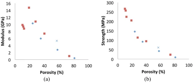
The tensile modulus and strength of the dry networks are shown in Figure 5. It can be clearly seen that there is a non-linear relationship between the modulus and the porosity and the strength and the porosity, and that decreasing the fibre content has a considerable impact on the strength and stiffness of the network. What is perhaps surprising is that the strength of the kraft reference paper also follows
this curve and that the modulus lies only slightly higher than the trend for CNF networks. Plotting data from other studies, it can be seen that they also follow the trend shown by this data for the strength and stiffness, though for the stiffness, the Tempo oxidized CNF lie off the main trend line. This suggests that the strength, and to some extent the stiffness, of dry CNF is highly dependent on the ability of these networks to form highly dense structures.
Figure 5: (a) the modulus and (b) the strength of the CNF networks of different porosities. In both cases, blue diamonds mark the results of this study for CNF networks; red squares mark the data from
other studies (see Appendix Table A1 for more details). The cross marks the kraft paper results.
4.2 Nanocomposites
The effect of the impregnation in the different infusion planes on the stress-strain behaviour of the WD and AD networks is shown in Figure 6. The WD composite has decreased in properties from the dried network from 11 to 7.1 GPa in modulus and from 140 to 103 GPa in strength. However, on impregnation the AD network has greatly increased in modulus from 2.8 up to 8.1 GPa and in strength from 42 to 91 GPa. For the kraft composite, the modulus increased to 9.5 GPa and 113 MPa in strength.
Figure 6: Typical stress-strain curves for (a) WD network and its composites and (b) AD network and its composites. Blue solid line is the network without resin, the red dotted line is the xy-plane infused nanocomposite and the green dashed line is the z-plane infused composite.
From Figure 6, it can be seen that the addition of the matrix has had two different effects. In the
(a)
(b)
WD, the relationship between stress and strain is not affected by the matrix, although the absolute values are lower. This is consistent with the fact that WD is not impregnated and the matrix lies mainly on the surface of the network, increasing the thickness but not contributing to stress transfer between the nanofibres. Whereas, in the case of the AD, the behaviour is changed considerably from the low yield and high plasticity of the non-impregnated network to a composite where the yield strength and ultimate strength are equivalent. Thus, the matrix appears to have impregnated the network and is contributed to the stress transfer in the material. For the low porosity networks, impregnation with the matrix greatly improves the mechanical properties however the ultimate strength and stiffness of the composite is lower than that of the kraft paper composite, indicating that the impregnation whilst improved is not complete and mechanical properties of the CNF composite rely on the properties of the network rather that the properties of the nanofibres themselves.
For the xy plane, the resin did not reach the end of the network within the gel-time of the resin for the AD and the FD network. Hence the composite tested was taken from the initial part of the flow path, where impregnation had occurred. The results show that in this initial part the composite appeared to be better impregnated, as indicated by the high yield strength of the AD composite.
9 CONCLUSIONS
In conclusion, increasing the porosity increases the permeability in CNF networks but it is several orders of magnitude higher than that of the kraft paper of the same porosity.
In addition, increasing the porosity lowers the predicted fill-time if the grammage is kept constant, up to a porosity of approximately 50% at which point the fill-time increases.
The mechanical properties of the dry networks show a negative exponential relationship between the porosity and the strength and the porosity and the stiffness. Values for stiffness, strength and porosity published in other articles on CNF networks also follow these trends with the exception of the stiffness of Tempo oxidised CNF. These trends show that the mechanical properties of the CNF networks rely heavily on the density of the packing of the fibres.
The CNF composites based on networks with wide differences in porosity showed quite different stress-strain behaviour and this is thought to reflect the level of impregnation. For the low porosity networks, impregnation with the matrix greatly improves the mechanical properties however the ultimate strength and stiffness of the composite is lower than that of the kraft paper composite, indicating that the impregnation whilst improved is not complete and mechanical properties of the CNF composite rely on the properties of the network rather that the properties of the nanofibres themselves.
Overall the results shows that in CNF composites produced by VI, lowering the fibre volume content of the CNF composites gives better impregnation, particularly in the xy plane, resulting in a lower ultimate strength but higher yield strength and no loss in modulus. Thus, strategies for exploiting infusion of CNF networks in the xy plane should be considered.
ACKNOWLEDGEMENTS
We gratefully acknowledge Bio4Energy, a Swedish strategic program, for the financial support and the County Council of Norrbotten, Sweden (Excel project)
REFERENCES
[1] Oksman K, Mathew AP, Sain M. Novel bionanocomposites: processing, properties and potential applications. Plast Rubber and Compos, 38, 2009, pp. 396-405. (doi 10.1179/146580109X12540995045723)
[2] Nakagaito AN, Yano H. Novel high-strength biocomposites based on microfibrillated cellulose having nano-order-unit web-like network structure. Appl Phys A 80 2005, pp. 155-159. (doi 10.1007/s00339-003-2225-2 )
[3] Lee K, Aitomäki Y, Berglund LA, Oksman K, Bismarck A. On the use of nanocellulose as reinforcement in polymer matrix composites. Composites Sci Technol 105 2014, pp. 15-27(doi 10.1016/j.compscitech.2014.08.032)
[4] Henriksson M, Berglund LA. Structure and properties of cellulose nanocomposite films containing melamine formaldehyde. J Appl Polym Sci 106, 2007, pp. 2817-2824. .(doi 10.1002/app.26946 )
[5] Lee K, Tammelin T, Schulfter K, Kiiskinen H, Samela J, Bismarck A. High Performance Cellulose Nanocomposites: Comparing the Reinforcing Ability of Bacterial Cellulose and Nanofibrillated Cellulose. ACS Appl Mater Interfaces 4, 2012, pp 4078-4086. (doi 10.1021/am300852a)
[6] Aitomäki Y, Oksman K. Reinforcing efficiency of nanocellulose in polymers. React Funct Polym 85 2014 pp. 151-156.( doi 10.1016/j.reactfunctpolym.2014.08.010 )
[7] Bear J. Dynamics of Fluids in Porous Media. Dover, 1972.
[8] Lundström TS, Stenberg R, Bergström R, Partanen H, Birkeland PA. In-plane permeability measurements: a nordic round-robin study. Comp Part A-Appl S 31 2000, pp. 29-43.( doi 10.1016/S1359-835X(99)00058-5)
[9] Jonoobi M, Aitomäki Y, Mathew AP, Oksman K. Thermoplastic polymer impregnation of cellulose nanofibre networks: Morphology, mechanical and optical properties. Composites Sci Technol 58 2014, pp. 30-35.( doi 10.1016/j.compositesa.2013.11.010 )
[10] Henriksson M, Berglund LA, Isaksson P, Lindström T, Nishino T. Cellulose Nanopaper Structures of High Toughness. Composites Sci Technol 9 2008, pp. 1579-1585. (doi 10.1021/bm800038n )
[11] Lundström T, Toll S, Håkanson J. Measurement of the permeability tensor of compressed fibre beds. Transp Porous Media 47 2002 pp. 363-380. (doi 10.1023/A:1015511312595 )
[12] Sehaqui H, Zhou Q, Ikkala O, Berglund LA. Strong and tough cellulose nanopaper with high specific surface area and porosity. Biomacromolecules 12, 2011, pp. 3638-3644. (doi 10.1021/bm2008907 )
[13] Ouagne P, Bréard J. Continuous transverse permeability of fibrous media. Comp Part A-Appl S
41, 2010, pp. 22-28.( doi 10.1016/j.compositesa.2009.07.008 )
[14] Fukuzumi H, Saito T, Isogai A. Influence of TEMPO-oxidized cellulose nanofibril length on film properties. Carbohydr Polym 93, 2013, pp. 172-177. (doi 10.1016/j.carbpol.2012.04.069)
APPENDIX Table A1
Network type Modulus (GPa) Strength (MPa) Strain at failure (%) 𝜖 Reference Water-dried TO-CNF a 9.8 266 9.9 10 [14] Water-dried TO-CNF b 9.4 257 9.0 11 [14] Water-dried TO-CNF c 8.8 224 8.9 12 [14] Water-dried CNF 14.7 205 6.9 19 [10] Methanol-dried CNF 10.8 114 5.4 28 [10] Acetone-dried CNF 7.3 95 1.2 40 [10] Freeze-dried CNF 1 23 5.7 74 [12]