Multidisciplinary Design Automation:
Working with Product Model
Extensions
Licentiate ThesisTim Heikkinen
Jönköping University School of Engineering
Licentiate Thesis in Machine Design Multidisciplinary Design Automation: Working with Product Model Extensions Dissertation Series No. 037
© 2018 Tim Heikkinen Published by
School of Engineering, Jönköping University P.O. Box 1026 SE-551 11 Jönköping Tel. +46 36 10 10 00 www.ju.se Printed by BrandFactory AB 2018 ISBN 978-91-87289-38-5
Acknowledgements
This work has been carried out at Sweden’s Jönköping University in the department of Product Development and the Computer-Supported Engineering Design research group. I am very grateful to Sweden’s innovation agency (Vinnova) for funding the research project abbreviated ChaSE, the Knowledge Foundation (KK-stiftelsen) for funding the research project abbreviated Impact and Region Jönköping County and Jönköping University for co-founding the research project abbreviated ProAct. Special thanks must be extended to the employees of the industrial partners within these projects who have given invaluable feedback and access to real-world contexts.
I would like to express my appreciation to Fredrik Elgh and Joel Johansson who initially introduced me to the wonderful world of design automation and who have given me this opportunity to learn how to perform research within it. Thank you for supporting me through this journey so far.
I would like to offer my special thanks to Samuel André, Sara Kallin, Tim Hjertberg, and Morteza Poorkiany for fruitful discussions. Thank you to all colleagues at the department of Product Development and the Computer-Supported Engineering Design research group, in particular, for contributing to a pleasant working environment.
Finally, thank you to my family and friends for your continuous encouragement and support.
Abstract
Being able to efficiently and effectively provide custom products has been identified as a competitive advantage for manufacturing organizations. Product configuration has been shown to be an effective way of achieving this through a modularization, product platform and product family development approach. A core assumption behind product configuration is that the module variants and their constraints can be explicitly defined as product knowledge in terms of geometry and configuration rules. This is not always the case, however. Many companies require extensive engineering to develop each module variant and cannot afford to do so in order to meet potential customer requirements within a predictable future. Instead, they try to implicitly define the module variants in terms of the process for how they can be realized. In this way they can realize module variants on demand efficiently and effectively when the customer requirements are better defined, and the development can be justified by the increased probability of profiting from the outcome.
Design automation, in its broadest definition, deals with computerized engineering support by effectively and efficiently utilizing pre-planned reusable assets to progress the design process. There have been several successful implementations reported in the literature, but a widespread use is yet to be seen. It deals with the explicit definition of engineering process knowledge, which results in a collection of methods and models that can come in the form of computer scripts, parametric CAD-models, template spreadsheets, etc. These methods and models are developed using various computer tools and maintained within the different disciplines involved, such as geometric modeling, simulation, or manufacturing, and are dependent on each other through the product model. To be able to implement, utilize, and manage design automation systems in or across multiple disciplines, it is important to first understand how the disciplinary methods and models are dependent on each other through the product model and then how these relations should be constructed to support the users without negatively affecting other aspects, such as modeling flexibility, minimum documentation, and software tool independence.
To support the successful implementation and management of design automation systems the work presented here has focused on understanding how some digital product model constituents are, can, and, to some extent, should be extended to concretize relations between methods and models from different tools and disciplines. It has been carried out by interviewing Swedish industrial companies, performing technical reviews, performing literature reviews, and developing prototypes, which has resulted in an increased understanding and the consequent development of a conceptual framework that highlights aspects relating to the choice of extension techniques.
Appended papers
Paper I
Tim Heikkinen, Joel Johansson, and Fredrik Elgh, “Extended CAD-models – State of Practice within Three Companies,” International Conference on Industrial Engineering and Engineering Management, Singapore, 2017.
Work distribution: Tim Heikkinen planned and executed the interview study and wrote the paper. Joel Johansson and Fredrik Elgh helped choose case companies and provided contact information, in addition to structuring and proofreading the paper. Paper II
Tim Heikkinen, Joel Johansson, and Fredrik Elgh, “Review of CAD-model Capabilities and Restrictions for Multidisciplinary Use,” Computer-Aided Design and Applications, 2018.
Work distribution: Tim Heikkinen performed the technical review and developed the prototype system and wrote the paper. Joel Johansson provided access to an implementation of the reviewed FEA automation method, described how it worked, contributed to the technical review through discussions, and helped with structuring and proofreading the paper. Fredrik Elgh mainly helped to structure and proofread the paper.
Paper III
Tim Heikkinen, Joel Johansson, and Fredrik Elgh, “Extended Design Assets Enabling Automated Tool Development as a Part of a Product Platform Approach,” International Design Conference, Croatia, 2018.
Work distribution: Tim Heikkinen developed the prototype system and wrote the paper. Joel Johansson supported the author by contacting the case company, choosing the production preparation focus, and structuring and proofreading the paper. Fredrik Elgh mainly lent support with the paper structuring and proofreading.
Paper IV
Tim Heikkinen, Joel Johansson, and Fredrik Elgh, “Multidisciplinary Design Automation – A Conceptual Framework for Working with Product Model Extensions,” submitted to an international journal.
Work distribution: Tim Heikkinen developed the conceptual framework and wrote the paper. Joel Johansson and Fredrik Elgh helped to structure and proofread the paper.
Additional papers
Paper V
Tim Heikkinen, Joel Johansson, and Fredrik Elgh, “Assessment of Simulation Ready CAD Models in a Set-Based Concurrent Engineering Context,” International Design Conference, Croatia, 2016.
Paper VI
Tim Heikkinen, Roland Stolt, Fredrik Elgh, and Petter Andersson, “Automated Producibility Assessment Enabling Set-Based Concurrent Engineering,” Transdisciplinary Engineering, Brazil, 2016.
Contents
1. Introduction ... 1
1.1. Motivation for research ... 2
1.2. Aim and goal ... 3
1.3. Research questions... 3
1.4. Scope and delimitations ... 4
1.5. Research projects ... 4 1.6. Thesis outline ... 5 2. Research approach ... 7 2.1. DRM ... 7 2.2. Interview ... 9 2.3. Action research ... 9
2.4. Applying the research approach ... 10
2.5. Evaluation ... 12 3. Frame of reference ... 13 3.1. Multidisciplinary DA ... 13 3.1.1. KBE ... 15 3.1.2. Configuration systems ... 15 3.2. Product development ... 16
3.3. Computer-based product modelling ... 17
3.3.1. Product model ... 18
3.3.2. Extensions to product model constituents ... 18
3.4. Customization ... 20
3.4.1. Product configuration ... 21
3.4.2. Product platforms ... 21
3.5. Summary and research opportunity ... 22
4. Summary of papers ... 24
4.1. Paper I – Interviews ... 24
4.1.2. Additional aid ... 27
4.1.3. Link or store ... 27
4.2. Paper II – Technical review ... 28
4.2.1. Required additional aid for the extension techniques ... 31
4.2.2. Comprehensiveness of extension techniques... 31
4.2.3. Support for executable information in extension techniques ... 32
4.3. Paper III – Exploration ... 33
4.3.1. DA and extensions... 34
4.4. Paper IV – Conceptualization ... 37
4.4.1. DA systems ... 37
4.4.2. Extended product model ... 38
4.4.3. Digital product model constituents ... 39
4.4.4. Conceptual framework ... 40 5. Discussion ... 44 5.1. Research question 1 ... 44 5.2. Research question 2 ... 45 5.3. Research question 3 ... 46 5.4. Evaluation ... 47
5.4.1. Theoretical structural validity ... 47
5.4.2. Empirical structural validity ... 47
5.4.3. Empirical performance validity ... 48
5.4.4. Theoretical performance validity... 48
5.5. Clarifications ... 48
5.5.1. Engineered-to-order-related businesses ... 49
5.5.2. Extended CAD-models ... 49
5.5.3. Extended design assets ... 49
6. Conclusions ... 50
6.1. Future work... 51
1
1. Introduction
Being able to efficiently and effectively provide custom products has been identified as a competitive advantage for manufacturing organizations. Product configuration has been shown to be an effective way of achieving this through a modularization, product platform and product family development approach (Pakkanen, Juuti and Lehtonen, 2016). Modularization is a process of partitioning a product into blocks. Reasons for doing so can be found throughout the product life cycle, such as carryover, technological evolution, planned design changes, process and/or organization reuse, etc. (Erixon, 1998). Product platform development emphasizes the reuse of shared aspects of a set of products (Robertson and Ulrich, 1998) and product family development stresses the definition of necessary product variants to fulfill the needs of a market within a predictable future (Lehtonen et al., 2003). A core assumption behind this approach is that the module variants and their constraints can be explicitly defined as product knowledge in terms of geometry and configuration rules. This is not always the case, however. Many companies require extensive engineering in order to develop each variant and cannot afford to do so in order to meet all potential requirements of a customer segment within any predictable time frame (André et al., 2017). Instead, they implicitly define the module variants by explicitly defining the process knowledge for how module variants can be realized. In this way, they can efficiently realize module variants on demand when the customer requirements are better defined, and the development can be justified by the increased probability of profiting from the outcome.
Developing a product (or module variant) is a continuous cycle of synthesizing and analyzing product specifications, such as requirements, bills of material, manufacturing equipment, and delivery processes. The formal representation of the product data created is called a product model, which is structured according to a product information model (Yang et al., 2008). In practice, product models are commonly constructed utilizing various CAx tools, spreadsheet applications, word processors, text editors, etc. These tools all use their own information models, which are focused on different data types, for different purposes. It is then up to the users to utilize the modeling techniques available to form a coherent product model.
Design automation (DA), in its broadest definition, deals with computerized engineering support by effectively and efficiently utilizing pre-planned reusable assets to progress the design process (Cederfeldt and Elgh, 2005). In other words, it deals with the formalization of engineering process knowledge, which results in a collection of methods and models that can come in the form of computer scripts, parametric CAD-models, template spreadsheets, etc. These methods and models are developed
2
using various computer tools and maintained within the different disciplines involved, such as geometric modeling, simulation, or manufacturing, and are dependent on each other through the product model. When using the product model, to support efficient and effective information handling and procedural processing between activities and projects, it is necessary to include information related to the process, rather than the product specifications themselves. Process-related information can be found in many different forms, such as annotations on CAD-model entities or notes on spreadsheet cells and can be human and/or computer interpretable. The information is used to manifest relations which can be used as identifiers for input, handles, or containers for downstream methods and models.
To be able to implement, utilize, and manage DA systems over time, with respect to process iterations and the introduction of new or updated technologies and organizational changes, it is important to first understand how the disciplinary methods and models are dependent on each other through the product model and then how these relations should be constructed. The work presented here has focused on understanding how some digital product model constituents are, can, and, to some extent, should be extended to concretize relations between methods and models from different tools and disciplines.
1.1. Motivation for research
To support customization in manufacturing companies with an engineer to order related business approach, DA can be used to support an efficient information exchange in computer-based product modeling, as well as attain new design exploration and optimization capabilities. Several examples of successful implementations of DA have been shown (La Rocca and Van Tooren, 2007; Haque, 2012). However, it has been said that a widespread use is yet to be seen (Tarkian, 2012), especially within small and medium enterprises (Colombo et al., 2015). Reasons for this are not clear, but a lack for quantitative measures for its potential benefits (Verhagen et al., 2015) and difficulties in selecting the appropriate methods (Rigger, Shea and Stankovic, 2018) are being explored.
To be able to implement, utilize, and manage DA systems over time, with respect to process iterations and the introduction of new or updated technologies and organizational changes, it is also important to first understand how the system constituents are dependent on each other and then how these relations should be constructed to support maintenance, leveraging, and future reuse. Being aware of the concrete representation of relations could support the traceability and transparency of the system (Hjertberg et al., 2018), and, depending on the technique chosen, comprehension and extendibility can be affected (Heikkinen, Johansson and Elgh, 2018a).
3
1.2. Aim and goal
The aim of this research is to increase the understanding and provide support for the development of multidisciplinary DA systems, focusing specifically on how to concretize relations between methods and models conformed within different disciplines using different tools. The goal is broadly to enable customization for companies that employ a business approach where a level of engineering is required to meet customer requirements and have a need to become more efficient and effective. Specifically, the goal is to construct a framework which can be used to choose extension techniques to embody relations which provide the best possibility to succeed in implementation, as well as in the future maintenance and reuse of DA systems.
1.3. Research questions
The research focuses on improving the understanding of how digital product model constituents are, can, and, to some extent, should be extended to concretize relations when automating design, over various computer tools and product modeling techniques in multiple disciplines. The questions are tightly integrated with the research approach described below and start with a focus on the clarification of the research by first looking at the current state of extending product models:
RQ1. What is the state of the art and practice of product model extensions?
The second research question focuses on forming a foundation from which the support can be guided and the end goal can be assessed:
RQ2. What are the industrial requirements for product model extensions?
Finally, the third question deals with the support that should improve the current state in conforming to the requirements identified.
RQ3. How can product model extensions be used to support multidisciplinary DA?
4
1.4. Scope and delimitations
The research presented here aims at developing an increased understanding and supporting models general enough to be applicable to manufacturing organizations utilizing computer-based product modeling for customized products. Investigating a statistically significant sample of these organizations to validate the models is not possible with the currently available time and resources. However, having the opportunity to work within three research projects made it possible to investigate three companies with respect to the state of practice and the requirements of product model extensions, and it provided the opportunity to explore the development of a DA system firsthand at one of them.
1.5. Research projects
The research presented in this licentiate thesis has been conducted in collaboration with three research projects: ChaSE, Impact, and ProAct.
Challenge Fluctuating and Conflicting Requirements by Set-Based Engineering (ChaSE) was a 3-year project starting in 2013 and financed by Vinnova, which aimed to develop “A novel method to develop and describe adaptive technology solutions with an ability to manage changing and conflicting requirements in the development of customized products.”
Efficient Implementation and Management of Systems for Design and Manufacture of Custom Engineered Products, known as Impact, was a 3-year project financed by the Knowledge Foundation and started in 2014 with the objective “to develop information structures, methods, models and tools that will allow companies to efficiently implement and maintain automated, computer assisted design and development practices that let them offer increased customization options towards customers.”
Platform Models for Agile Product Development – Building an Ability to Adapt, known as ProAct, is an ongoing 3-year project which started in 2017 and is financed by Region Jönköping County and Jönköping University with an objective to “develop knowledge, methods and tools that will contribute to the scientific knowledge in platform development and to enable the industrial actors to increase their competitiveness by the introduction of new platform models, both general and application specific, that will enable them to tackle the challenges they face and to take advantage of the opportunities provided by new technologies and business models.”
These projects have provided access to multiple industrial partners, which has made it possible to investigate the phenomenon of product model extensions from an outside perspective, as well as from that of an active participant in real-world settings.
5
1.6. Thesis outline
The thesis is structured in six chapters, starting with Chapter 1 Introduction above, where mainly the research goals are presented with some background. Chapter 2
Research approach then gives a description of the main research stages and
techniques used, in addition to how they are applied and evaluated. This is followed by Chapter 3 Frame of reference, where some key areas of research are sketched out and summarized to reduce misconceptions of the words and concepts used, as well as to describe the related work and research opportunities. Next, Chapter 4 Summary of
papers gives a summary of the appended papers in order to outline the main results,
which are then used to answer the research questions. Chapter 5 Discussion addresses the research questions and evaluation of the research and includes some clarifications. Finally, Chapter 6 Conclusions concludes the thesis and points out potential areas for future work.
7
2. Research approach
The research is constructed on two levels of detail. First, a general approach is formed according to Design Research Methodology (DRM) which divides the work into four distinct phases portraying the basic means and main outcomes from each. Second, the basic means in each step is developed as the process progresses. Interviews are used to collect empirical data about the state of practice and action research for a more detailed understanding of the phenomenon and the synthesis of support. Following is a more detailed description of the research methodology and techniques, including how they were applied and evaluated.
2.1. DRM
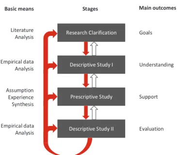
DRM is a general research framework for conducting research with a prescriptive nature. The main goal is to improve the current understanding and develop support for the design phenomena. Design is used for describing “the process through which one identifies a need, and develops a solution––a product––to fulfil the need” (Blessing and Chakrabarti, 2009). It is comprised of four distinct phases, as illustrated in Fig. 1. It is described here as a sequential process, but iterations among the different stages are possible. Staying flexible and “goal driven” has shown to be positive in many cases (Blessing and Chakrabarti, 2009). It is also possible to focus on specific stages. This all depends on the intended outcome, as well as time and funding available.
In stage one, called Research Clarification, the focus is primarily on understanding and describing the current situation and identifying the goal of the study. Furthermore, necessary areas of investigation are clarified, and preliminary success criteria are defined. It provides clarification upon which later stages can focus. The main outcome is a set of defined goals.
Stage two, called Descriptive Study I, is an elaboration of the first stage by performing empirical studies. It further improves upon the understanding of the current situation, which gives clarification on which criteria are suitable. Suggestions are also made for the next stage, wherein the support is developed, specifically as to which factors must be kept in mind. The main outcome is an improved understanding and details which can be useful when developing and evaluating the suggested support.
8 Research Clarification Descriptive Study I Prescriptive Study Goals Understanding Support Evaluation Literature Analysis Empirical data Analysis Assumption Experience Synthesis Empirical data Analysis
Basic means Stages Main outcomes
Descriptive Study II
Fig. 1. DRM phases (middle), basic means for each (left), and main outcomes (right).
Prescriptive study is stage three. This is where the suggested support is developed with help from the initial two stages. Evaluation of the actual support is made to ensure that it provides what it should, consistently. This evaluation is a precondition for moving on to the final stage. The main outcome is support.
The fourth and final stage, Descriptive Study II, is where the final evaluation takes place. This includes a series of essential questions: Did the suggested support meet the expected effects? Was the suggested support realistic, and how successful was it? What challenges are still present, and what assumptions have been made? The main outcome is an evaluation based on the answers to these questions.
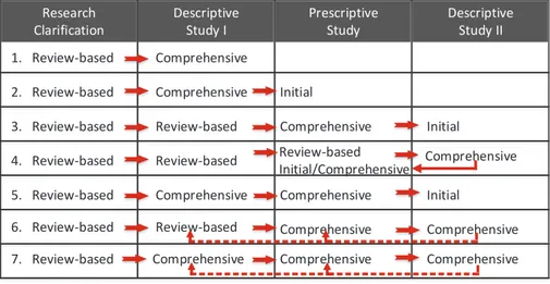
Performing all DRM stages comprehensively is a tall order. It is, however, not a necessity. Blessing and Chakrabarti describe seven possible types of research, depending on the preconditions and results sought (see Fig. 2).
Instead of performing a comprehensive study, where literature research is supported with an empirical study, one can opt for the review-based approach. In a review-based approach, the time and resources available depict the completion of a stage. This will play a negative role on the validation and/or verification of the study, however.
9
Fig. 2. Possible DRM research types.
2.2. Interview
Interviewing is a research technique often utilized for collection of qualitative data. There are three different types of interviews: structured, unstructured, and semi-structured. Depending on the level of structure in the interview, participants have a varied amount of freedom as to which topics to discuss and in what order. Structured interviews have a set of questions defined prior to the interview, and these are asked in the same way each time. Unstructured interviews, on the other hand, allow the answers to questions to influence where the interview goes. Unstructured interviews emphasize the perspective of the participant (Williams, 2002).
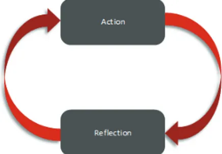
2.3. Action research
Action research is used within social sciences where the natural science approaches of hypothesis testing become implausible. To understand the problems and corresponding solutions within many social environments, the researcher can take part and try to draw objective knowledge from the situation he/she observes. Its validity as a scientific method has been argued for a long time (Susman et al., 1978). Its core issues are the lack of replicability, much due to the materials of social sciences not being homogenous with time, and, although its results may never acquire the same level of validity as natural science, it has been shown to produce general knowledge which can be transferred to other situations (Checkland and Holwell, 2007). It is comprised of two main tasks (see Fig. 3): action and reflection, or action and research (Williams, 2002). Research Clarification Descriptive Study I Prescriptive Study Descriptive Study II 1. Review-based 2. Review-based 3. Review-based 4. Review-based 5. Review-based 6. Review-based 7. Review-based Comprehensive Comprehensive Comprehensive Comprehensive Comprehensive Comprehensive Comprehensive Comprehensive Comprehensive Review-based Review-based Initial Initial Initial Comprehensive Review-based Review-based Initial/Comprehensive Comprehensive
10
The tasks are highly interconnected. Which action to perform is depicted by the reflections made, and reflections made give content to which reflection the action can be based upon. It resembles problem-solving activities as performed in day-to-day life, but, when used as a research method, emphasis is put on systematism, clear definitions of the frameworks used, the method/model under investigation, and the area for which it is applied, as well as the reflections supported by conclusions drawn by other researchers.
Fig. 3. Action research main tasks.
2.4. Applying the research approach
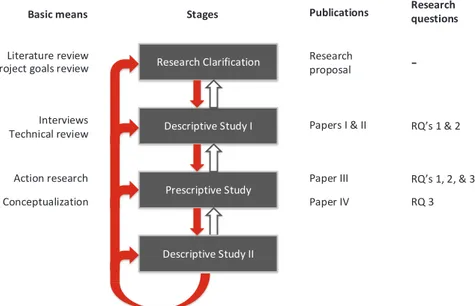
The general approach was formed according to DRM, which divided the work into four distinct phases. Fig. 4 displays the basic means, publications, and which research question(s) was focused on for each phase. The work started from top to bottom and conforms the best with research type no. 2 in Fig. 2, from review-based Research Clarification to comprehensive Descriptive I and an initial Prescriptive phase. As the work progressed, continuous refinements were made to previous phases. In particular, the necessary areas of concern in Research Clarification were expanded as new topics of interest were identified through literature reviews and in the interaction with industries and other researchers.
During the Research Clarification phase, a literature review was the basis upon which a research proposal was composed and presented. In addition, the research project goals at the time were reviewed, and the general focus was defined in terms of research questions.
In the Descriptive I phase, nine interviews were performed at three Swedish industrial companies. The results have been presented and discussed in Paper I. Interviews were used to clarify the research topic from an industrial point of view and to identify the challenges in an objective manner. If the topics under investigation would have been well-known, beforehand, a structured interview approach would have been applied, but, instead, a varying degree of flexibility was allowed conforming to an unstructured approach. All the interviews were recorded,
11
transcribed, categorized, and summarized. A technical review was also performed to grasp the technical capabilities and restrictions with respect to the research in the Descriptive I phase. These results formed a list of criteria for improvement, which guided the Prescriptive phase and provided a foundation for evaluation in the Descriptive II phase. The results have been presented and discussed in combination with Paper I in Paper II.
In the Prescriptive phase of DRM, a study of action research characteristics was performed. Action research was applied by finding an appropriate, willing, and able industrial company where frequent visits could be made to develop understanding and support for the topic under investigation. The case focused on the automation of tool-insert development at a case company and involved gathering and analyzing company specific documentation, recording practitioners at work, collaborating with practitioners, and gathering reflections from practitioners. The results have been presented and discussed in Paper III. A conceptualization was also done to initiate the development of a framework supporting the extension of product model constituents to support successful multidisciplinary DA. It was done by analyzing the work conducted in the interviews and action research study. The results are formalized in Paper IV. Research Clarification Descriptive Study I Prescriptive Study Research proposal Papers I & II Paper III Literature review Interviews Technical review Action research
Basic means Stages Publications
Descriptive Study II Conceptualization Paper IV Research questions RQ s 1 & 2 RQ s 1, 2, & 3 RQ 3
-Project goals review
Fig. 4. Overview of DRM phases and their relationship with publications and research questions.
12
2.5. Evaluation
To ensure that the research conducted is of good quality, the results need to be evaluated. Within design science, conducting scientifically acceptable evaluations is difficult because of its stochastic nature (it may increase the probability of improving something but does not guarantee it) and the sheer number of influencing variables (Buur, 1990), not to mention the characteristic of design processes being inhomogeneous with time (change with time). An experiment where proposed design methods are tested in real-world settings often requires access to a company and its resources, as well as their employees’ time and compliance to try new things, both of which most companies are not willing to share or accept on first contact. In addition, many design methods can require initial investments, and profit might not come until several years later. All these aspects (and more) make evaluation which complies with natural science criteria implausible. Instead, other methods need to be employed.
Evaluation of design methods can be made in accordance with the validation square, as presented in (Pedersen et al., 2000). In this approach, the evaluation is more of a process of building confidence in the proposed methods to be useful with respect to some purpose. The evaluation focuses on verification and validation separately, defined in terms of internal consistency and justification of knowledge claims, respectively, as defined in (Barlas and Carpenter, 1990). There are four aspects which are considered in the validation square (see Fig. 5):
• Theoretical structural validity – structural soundness of method in general. • Empirical structural validity – appropriateness of example problems used to
verify method usefulness.
• Empirical performance validity – performance of design solutions and method with respect to example problems.
• Theoretical performance validity – performance of design solutions and method beyond example problems.
• Theoretical structural validity Theoretical performance validity Empirical structural validity Empirical performance validity
• Fig. 5. Validation square (Pedersen et al., 2000). These aspects will be addressed with respect to the research results presented.
13
3. Frame of reference
This research has mainly centered around developing the research area of DA to support product development and computer-based product modeling to enable
customization. Each of the main concepts used in this thesis are described here as a
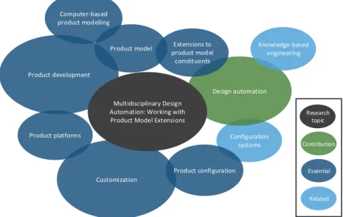
frame of reference, including essential and related concepts and research fields (see Fig. 6 for an overview). This section concludes with a summary emphasizing research opportunities. Configuration systems Design automation Customization Product development Product model Multidisciplinary Design Automation: Working with Product Model Extensions Computer-based product modelling Knowledge-based engineering Product platforms Extensions to product model constituents Product configuration Research topic Essential Related Contribution
Fig. 6. Overview of the essential (dark blue) and related (light blue) concepts and research fields for the development of the main research field (green) in this
research topic (black).
3.1. Multidisciplinary DA
DA, in its broadest definition, deals with computerized engineering support by effectively and efficiently utilizing pre-planned reusable assets to progress the design process (Cederfeldt and Elgh, 2005). Multidisciplinary DA means that the processes within multiple disciplines, e.g., classical mechanics, fluid-dynamics, thermo-dynamics, and design, are taken into consideration.
DA has been defined as a distinct separate method, opposed to knowledge-based engineering (KBE), for the development of automated design systems (Van der Velden, 2008), but also as a general method used for enhanced computer support,
14
where KBE is one of several such methods (Cederfeldt and Elgh, 2005). In this work, the latter will be used for semantic reasons (KBE also deals with the automation of design tasks). Support for this can be found in Rigger, Münzer, and Shea (2016), where the potential of DA systems is discussed and several KBE systems are used to exemplify how time savings are regularly used to quantify DA system success. Moreover, further discussions have examined the relationship between KBE and computational design synthesis (Rigger, Shea and Stankovic, 2018). DA systems can therefore provide computer support in terms of conventional procedural systems and intelligent systems, such as KBE systems. Hopgood (2001) gives a comprehensive description of different intelligent systems.
It has been said that a widespread use of DA is yet to be seen (Tarkian, 2012), especially within the small and medium enterprises (Colombo et al., 2015). The reasons for this are not clear, but a lack of quantitative measures for its potential benefits (Verhagen et al., 2015) and difficulties in selecting the appropriate methods (Rigger, Shea and Stankovic, 2018) are being explored.
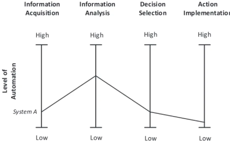
Sometimes, it can be more relevant to discuss levels and types of automation. A study by Parasuraman, Sheridan, and Wickens (2000) presents a level of automation (LoA) scale from 1 (no assistance is given) to 10 (the system is completely autonomous and ignores the human agent), along with four types of automation: information acquisition, information analysis, decision selection, and action implementation. Fig. 7 shows how a system can vary in its LoA and type.
High Low High Low High Low High Low Information Acquisition Information Analysis Decision Selection Action Implementation Le v el of A ut om at io n System A
Fig. 7. Types and levels of automation for a system (Parasuraman, Sheridan and Wickens, 2000).
15
3.1.1. KBE
KBE originates from research within knowledge-based systems in the artificial intelligence field. Essentially KBE is knowledge-based systems theory applied to the engineering field (Rocca, 2012). It can be seen as the connection between computer-aided design (CAD) and computer-computer-aided analysis tools, including the reasoning and knowledge capturing and representation provided by knowledge-based systems (Rocca, 2012). KBE is usually referred to as a method for the capture and reuse of product and process knowledge to automate repetitive tasks (Stokes, 2001). The main difference between a knowledge-based system and a conventional program is the separation of the knowledge base, or knowledge module, and the inference engine, or control module. Several examples of KBE methods used for solving the integration issues of different design activities, such as high level primitives, have been presented (Nawijn et al., 2006; Tarkian, 2012).
3.1.2. Configuration systems
“A configurator is a piece of software that assists the person in charge of the configuration task. It is composed of a knowledge base that stores the generic model of the product and a set of assistance tools that help the user to find a solution or to select components. In any case, the basic common requirement, in terms of assistance, is to guarantee that the configured product is consistent (all constraints are respected) with the generic model and the requirements, during and at the end of the configuration task.” (Aldanondo and Vareilles,
2008)
In other words, configuration systems assist in configuration tasks. There is a vast pallet of different types of tasks which fall into this category, such as scheduling (e.g., lectures or manufacturing activities), allocation (e.g., floor plan layout), or solving crossword puzzles. The configuration tasks are modelled in terms of variables with associate domains (a collection of possible values) and constraints. The task can then be to answer whether there are any solutions (it is possible to assign at least one value for each domain without violating constraints), removing values in domains which are not part of any solution (constraint propagation), finding a solution, or finding an optimal solution according to a function (Dechter, 2003). They are usually solved utilizing various constraint programming methods, which originate from research within computer science, artificial intelligence, and operations research (Rossi, Beek and Walsh, 2006). Propagating constraints to achieve high levels of consistency (removing values in domains which violate constraints) when the number of variants grow, or applying constraints among several domains, quickly makes this task highly complex or even computationally impossible within a reasonable time frame. One
16
way of dealing with this is to apply a procedure for the configuration task, where some domains are left implicitly defined until some related domains have been reduced.
3.2. Product development
Product development (PD) is an organizational business process within a company calling for a set of requirements, defined by a market need or opportunity, for delivering a product model. On a general level, PD can be said to be seen from four main perspectives: marketing, organization, engineering design, and operations management (Krishnan and Ulrich, 2001). Each deals with different levels of product detail and utilizes different sources of knowledge. These sources of knowledge are what this thesis will denote as disciplines, also commonly referred to as fields of study. Examples within the engineering design perspective are classical mechanics, fluid- and thermo-dynamics, and design. Collaboration between these disciplines is crucial, as they work with the same product model but with different agendas, often resulting in conflicting aspirations. The knowledge involved when developing products can also be categorized as product and process knowledge (Zha and Sriram, 2006). Product knowledge refers to the outcome from design activities and process knowledge to the activities themselves.
Digitalization is a trend which is also manifesting itself in product development. For instance, to increase the competitive potential within manufacturing companies, a number of different types of computer simulations have been introduced to improve the effectiveness and efficiency of the engineering design process. As indicated in Petersson et al. (2015), where 77 people answered a survey, about 35% of them used computer-based design analysis and 28% expected to do so in the future. Simulations can, compared to physical tests, save a significant amount of time and money at the expense of losing some test reliability. Continuous improvements with the accuracy and efficiency of the simulations have expanded their use within product development. Initially, they were mainly concerned with assurance of the products’ performance, reliability, and manufacturing costs, but, today in some cases, they are also used to guide the development process (Karlberg, Löfstrand and Lundin, 2013).
The product development process can be divided into six distinct phases (see upper part of Fig. 8). In a perfect world, this process would be completely sequential (only follow the green arrows) and never require iterations, but this is not the case. The red arrows indicate how iterations are a natural part of the process. In the second row of Fig. 8, we see an evolving product model. It is the result of the activities performed during the different product development phases where several disciplines (lower part of Fig. 8) work with several different computer-based tools (third row of Fig. 8). Each tool creates its own model, and together they form a complete model of the product. The product model could also be represented in one or several common
17
standardized formats. More about the product model below will be explained in section 3.3.1.
Fig. 8. Illustration of the digital and iterative product development process, where multiple disciplines work with several tools to produce an increasingly digital product model.
3.3. Computer-based product modelling
Computer-based product modelling has developed from solid geometry focused, such as boundary representation (B-Rep) and constructive solid geometry (CSG), to feature-based, knowledge-based, and integrated (Yang et al., 2008). As the name indicates, B-Rep models represent the geometric model as a set of boundaries, where solids are represented by bounding faces which are, in turn, bounded by edges which are bounded by vertices. CSG instead represents the solid geometry as a result of applying set operations (union, difference, and intersection) between primitives, such as cubes, cylinders, and spheres. Feature-based product modelling, in contrast to B-Rep and CSG, focuses on non-geometric aspects, and enables reasoning about sets of information concerning a product (Salomons, van Houten and Kals, 1993). Feature-based modelling therefore supports the integration of downstream processes, such as net shape design (using molds or dies, in contrast to metal removal processes) (Chen and Wei, 1997). There are generally three approaches to create features: interactive feature recognition, automatic feature recognition, and design by feature (Shah and Mäntylä, 1995). Knowledge-based product modelling further expanded the modelling capabilities by incorporating product knowledge in terms of rules, which enabled the use of technologies developed within research in artificial intelligence, such as knowledge-based systems. Integrated product modelling incorporates geometric,
18
feature-based, and knowledge-based modelling methods in one product model to support integrated PD.
Introducing parameters and constraints made it easier to change geometric models (Hoffmann and Joan-Arinyo, 2002). In parametric CAD software, solid modelling operations (e.g., general feature operations such as extrude or rotate) are stored in a construction history tree, which can be modified later. The modifications can be made to independent parameters, which then propagate changes to dependent parameters by solving the constraints, and, if not procedural, the constraints are usually modelled and solved using graph-based approaches (Bettig and Hoffmann, 2011). Usually there is a directed relationship which requires users to plan ahead with respect to how changes propagate. This strong dependence of modelling approach and difficulty in understanding the controlling parameters (especially for users who did not model it) have resulted in direct modelling approaches. In direct modelling, the modelling operations are just added to the construction history, but parametric control is lost.
3.3.1. Product model
The deliverable of PD is a model of a product that can be utilized by marketing and sales, as well as production, to produce and sell products, including possible services, to customers. The PD phase of product realization is comprised of the product and its manufacturing specifications, which are formed in a design process utilizing different views of the information (Shooter et al., 2000). The outcome of product and PD should represent a complete and unambiguous recipe from which product instances can be produced and later product life information can be further attached. It is often the result of combined efforts from multiple disciplines and computer-based tools (see Fig. 8 in section 3.2).
Standard product models, such as ISO 10303 also known as Standard for the Exchange of Product model data (STEP), focus on the representation of product data to enable interoperability throughout the product life cycle and long-term storage and retrieval. These models have been developed from mainly focusing on the representation of design output in the form of geometry (Fenves et al., 2005) to non-geometric information, such as non-geometric dimensioning and tolerance. Core product model2 (CPM2), briefly described in Fenves et al. (2008), is another product model concept which further expands the scope to support information regarding geometry, function, form, behavior, material, etc.
3.3.2. Extensions to product model constituents
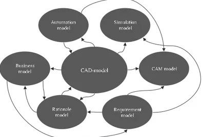
In practice, product models often consist of different types of models that utilize different computer-based tools within multiple disciplines (see illustrative example in
19
Fig. 9). To produce a coherent product model, a common standardized product model representation (information model) could be established and viewed by using the different model types. Another approach is to connect or integrate them by extending them with links and annotations of different kinds. Below is a summary of a few such examples.
Fig. 9. An example of different model types in a digital product model. An extended product model concept is presented by (Ding et al. (2007) to support a constraint-based redesign approach. It is centered around CAD-models which are extended with requirements, performance limits, alternative features, and many different types of links for the active product model but also historical instances. The purpose is mainly to capture and represent the design rationale in CAD-models.
Lightweight model with multi-layer annotation (LIMMA) (Ding, Davies and McMahon, 2009) is a similar approach developed by some of the same authors who detailed the extended product models described above. In contrast, however, LIMMA uses lightweight representations of geometry and an annotation markup approach stored inside or outside the CAD-model in XML format to enable reviewing and editing outside the CAD environment.
Lundin et al. (2017) present a CAD-model-oriented approach to support reuse within product family development. A suggested support approach is then presented where capture and representation are enabled through a custom CAD application integrated with the CAD tool to facilitate minimum investment and maximum reuse. The application utilizes 3D annotations associated with CAD features and model views, along with textual descriptions and links to external sources. All the information is then managed by a product life-cycle (PLM) system, which can be accessed and visualized using web applications.
20
Cederfeldt (2007) presents a design variable naming approach using a stringent taxonomy which not only enables a DA system to identify variables in different model types but also helps the human user in understanding and utilizing them. Ultimately, the naming convention makes it easy to identify relations and adds to the transparency of the system.
Model-based enterprise (MBE) is a paradigm which has adopted the model- based definition (MBD) methodology (Miller et al., 2017). Instead of only using model-based information as a way of replacing 2D drawings with 3D CAD-models, MBE has been described as a general way of supporting information consumption among any activity within an organization. Many of the examples found revolve around annotating 3D CAD-models as a means of making the geometry more comprehensive and, in this way, making the models more reusable (Trainer et al., 2016), as they are stored inside or outside the actual CAD-model (Camba et al., 2014).
3.4. Customization
Customers have shown an increased demand for customization of products. For this reason, some companies try to increase their market share by creating an ability to offer more product variants. Mass customization attempts “to provide customization using low-cost mass production methods” (Fogliatto, 2011, p. 35). It is highly coupled to modularity, which limits the choices a customer has and enables the higher volumes necessary for mass production. Modularization is a process of partitioning a product into blocks, and the reasons for doing so can be found throughout the product life cycle, such as carryover, technological evolution, planned design changes, process and/or organization reuse, etc. (Erixon, 1998).
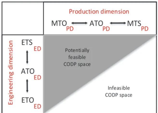
Another concept which is important for the operations strategy supporting customization is the customer order decoupling point (CODP). CODP defines the point at which customers are introduced and, ultimately, where a transition from speculation-based activities become customer order-based. In Wikner and Rudberg (2005), a CODP concept is introduced which includes both the engineering and production dimensions (see Fig. 10), while considering the integrated aspects. Depending on the required delivery lead time, the product can either be engineered-to-order (ETOED), adapted-to-order (ATOED), or engineered-to-stock (ETSED) within
the engineering dimension (subscript ED) and then made-to-order (MTOPD),
assembled-to-order (ATOPD), or made-to-stock (MTSPD) in the product dimension
(subscript PD). Since production needs the product specifications from engineering, some of the combinations are directly infeasible, however. Fig. 10 outlines a potentially feasible and infeasible space of COPDs and, at the same time, visualizes how the two disciplines affect each other, depending on where the customer is introduced. In extreme cases, ETOED requires MTOED, ETSED makes all production
21
CODP strategies possible, MTOPD opens for all engineering CODP strategies, and,
finally, MTSED requires ETSED.
Production dimension E n g in ee ri n g d im en si o n
MTO
PDETO
ED EDETS
ATO
PDMTS
PDATO
ED Potentially feasible CODP space Infeasible CODP spaceFig. 10. Adapted from Wikner and Rudberg (2005).
3.4.1. Product configuration
Product configuration has been shown to be an effective way of achieving mass customization through a modularization, product platform and product family development approach (Pakkanen, Juuti and Lehtonen, 2016). Modularization is a process of partitioning a product into blocks, and the reasons for doing so can be found throughout the product lifecycle, such as carryover, technological evolution, planned design changes, process and/or organization reuse, etc. (Erixon, 1998). Product platform development emphasizes the reuse or shared aspects of a set of products (Robertson and Ulrich, 1998), and product family development defines the necessary product variants to fulfill the needs of a market within a predictable future (Lehtonen
et al., 2003). When the reusable objects can be defined as predefined components, the
task of realizing a product which fulfils a customer’s needs becomes one of pure configuration. Product configuration can be supported by configuration systems for sales or engineering, configuration systems are discussed further in section 3.1.2.
3.4.2. Product platforms
A product platform has been defined in many ways; however, a shared element of these definitions is that it is a set of common objects is used to efficiently realize and launch products (Meyer and Lehnerd, 1997). In other words, it is a collection of objects which can be reused among products. Recent approaches in applying a product platform approach have included reusability of design aspects, as well (André et al.,
22
2017). In a way, these design assets can be seen as implicit definitions of some aspects of the product. However, since human creativity can be involved, there are aspects of randomness, and the process results can vary, even though the input, design assets, and tools are kept the same. Developing just one explicit platform component with all these factors can be difficult to know beforehand. This is because they might be high-level process descriptions with simple guidelines and heuristic rules.
Including design aspects within a product platform makes them similar to design repositories, which can be defined as an “intelligent knowledge-based design artifact modeling system used to facilitate the representation, capture, sharing, and reuse of corporate design knowledge” (Szykman et al., 2000, p. 2). It has been noted that significant efforts are still required between design repositories and DA modelling in CAD systems (Lyu, Chu and Xue, 2017).
3.5. Summary and research opportunity
Computer-based product modelling is a central part of product development and has undergone an evolution from focusing on geometric detail to feature, knowledge, and integration (Yang et al., 2008). Customization has been identified as a competitive advantage, which successfully enables utilizing the product configuration through a modularization, product platform and product family development approach (Pakkanen, Juuti and Lehtonen, 2016). Explicitly defining all module variants, which completely meet the requirements for a specific market and time frame, might not always be possible, or even desired, however. One reason for this is if customer requirements are uncertain and the realization of all components required to meet the potential customer requirements are not feasible. Developing some module variants might require extensive product and production development and testing for each unique customer requirement. This is why some companies apply an ETOED approach.
In these contexts, a more abstract product platform is also required that includes common assets relating to the design (André et al., 2017).
To support customization in ETOED business approaches, DA can be used to
support efficient information handling and attain new design exploration and optimization capabilities in computer-based product modelling. However, to enable any automation, the information is required to be standardized (Fenves et al., 2005; Chandrasegaran et al., 2013) and integrated with the available computer tools and knowledge modelling techniques (Lyu, Chu and Xue, 2017).
Extended product model examples have been presented in the literature for the following factors: supporting capture and representation of design rationale for constraint-based redesign (Ding et al., 2007); enabling association of product data throughout the product life cycle using lightweight geometric models extended with annotations (Ding, Davies and McMahon, 2009); 3D annotations associated with
23
CAD features and model views to support reuse in product family development (Lundin et al., 2017); a design variable naming approach using a taxonomy supporting transparency of DA systems (Cederfeldt, 2007); and the elimination of 2D drawings using annotations on 3D models (Trainer et al., 2016).
Similarly, to meet the objectives of the MBE approach and standard product model research, the research presented here focuses on how to support an efficient and effective use of information throughout the product realization process. There is a lack of research with respect to the different possibilities to extend product model constituents, however, and how these techniques relate to each other and how they could be used to support development, implementation, maintenance, and future use of multidisciplinary DA systems.
24
4. Summary of papers
A summary of contributions is presented here, sectioned and arranged according to the appended papers. To clarify the general relationship between research questions and the research approach, see Fig. 4 in section 2.4. It shows how the research questions were defined mainly using literature reviews and research project goal reviews and is followed by interviews and a technical review, action research, and conceptualization to gather support to answer them. The papers, which are the main outcomes, are summarized here and utilized in answering the research questions in the next section. Small changes in the summaries (compared to the original papers) have been made to support stringency.
4.1. Paper I – Interviews
The study focused on collecting empirical data with respect to non-traditional information on CAD-models. Questions such as why and how non-traditional information was added was addressed, as well as what the needs, challenges, and trends were. Three Swedish ETOED-related industrial companies with a long history
of extending CAD-models were investigated using interviews (see short description of companies below). Nine employees from different disciplines and positions, who were in some way connected to the extension of CAD-models, were selected to get several perspectives on the matter. The questions were structured to first focus on personal practice, followed by company-wide practice, and finally personal perceptions of trends. The interview was not fully structured, meaning that flexibility in the way that questions were expressed varied and were sometimes even skipped, while new questions could be added when interesting topics arose. In the end, a total of about four to five hours of recorded interview material was collected. An analysis was conducted by replaying the audio from the interview sessions. Moreover, each response to the questions was transcribed, categorized and then summarized for each company.
Table 1 below summarizes the seven extension techniques identified, and Table 2 shows from which company and discipline they were used. The three disciplines (simulation, geometry modelling, and manufacturing) mainly used the CAD-model as a carrier of information to enable automation of different kinds. The geometric modeler needed handles on parameters and reference planes to combine the different parts. The simulation discipline needed Finite Element (FE) specific information relating to the geometric entities, as well as simplified representations of the actual product form. This was added in the form of names, attributes, geometric entities, and programmed features. Manufacturing required complementary CAD-models
25
representing the manufacturing equipment and tools and process specific information. This was made possible by adding names, attributes, geometric entities (e.g., point with tolerance information), and entirely new CAD-models.
Every company in this study saw a trend in which extensions to the CAD-models were necessary. Three companies were selected for the case study:
Company I
This company develops and manufactures products that support an active life style. Some of the products are transport-centered, e.g., roof-boxes and bike carriers. This makes roof racks for cars an important product for the company, which is also a reason why this company has been selected as a target for this case study. Each roof rack is engineered to meet the unique geometric specifications of each car (further described in section 4.3).
Company II
Company II is a supplier of tools, tooling solutions, and know-how to the metalworking industry. This case study focused on a part of the company which develops parametrically defined product families with fully automated production specifications.
Company III
Company III is a global actor in development, production, service, and maintenance of components for aircraft, rocket, and gas turbine engines. They provide products that are completely custom-engineered in an international market with a high level of competition.
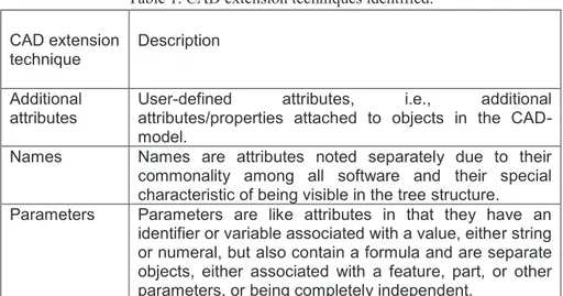
Table 1. CAD extension techniques identified. CAD extension
technique Description Additional
attributes
User-defined attributes, i.e., additional attributes/properties attached to objects in the CAD- model.
Names Names are attributes noted separately due to their commonality among all software and their special characteristic of being visible in the tree structure. Parameters Parameters are like attributes in that they have an
identifier or variable associated with a value, either string or numeral, but also contain a formula and are separate objects, either associated with a feature, part, or other parameters, or being completely independent.
26
Annotations Annotations are separate objects which can be used to link text and symbols to geometric entities.
Bundled
features Bundled features are user-defined collections of features, commonly referred to as user-defined features. Programmed
features Programmed features are essentially the same as bundled features but are more flexible, as they are created utilizing the software application programming interface. They are a way for the user to attach code to the model rebuild loop.
Additional
geometry Modelling geometry is the main objective of a CAD system and is usually found as one of four main types: point, curve, surface, or body.
Table 2. CAD extension techniques used within the different companies (CI–CIII) and disciplines (Sim: simulation, Geom: geometric modelling, and Manuf:
manufacturing) Extension
technique CI CII CIII Sim Geom Manuf
Names No Yes Yes Yes No Yes
Additional attributes No Yes Yes Yes No Yes
Parameters No Yes Yes No Yes No
Annotations No No No No No No
Bundled features No Yes No No Yes No Programmed
features Yes No Yes Yes No No
Additional geometry Yes Yes Yes Yes Yes Yes
4.1.1. Challenges
There were several challenges expressed during the interviews, such as managing a naming convention which was used with some of the extension techniques. Company I had been able to work without this by using programmed features, however. In addition to this challenge, a resentment was expressed with respect to the administration of the additional information, which usually fell on the geometry modeler, as well as managing software updates, modelling robust and flexible CAD-models, and managing the tradeoffs between mesh quality and size, geometric simplicity, and realistic product representations. When it comes to the management of the trade-off between geometric simplicity and realistic product representation, both Company I and II had methods where both models were represented. Company I focused on the definition of FE features from within the CAD software, utilizing the creation of new geometric entities constrained by the product CAD-model. Company II had automated the product model creation process using their own programming
27
language and could therefore skip different parts of the modelling to produce simplified models for simulation purposes.
4.1.2. Additional aid
All companies utilized some sort of script or software to facilitate the addition of information for the geometric modelers. Company I utilized programmed features which are instantiated using CAD software internal user interfaces with predefined inputs for different FE features. Company II had an automation system built upon the CAD software application programming interface (API) which added information at the same time as it merged the different CAD-models. Company III also had different scripts to read from spreadsheets and automatically add names and attributes once the final product model had been created, and, in this case, CAD internal scripts had been made and added to the different CAD-models and executed by a CAD software macro. Company III has also created quality checks by altering colors of geometric entities with the correct non-traditional information.
4.1.3. Link or store
A question which was discussed several times in the interviews was whether to link or store the additional information to/in the CAD-model. In many of the interviews, only a few initial handles to the CAD-models were expressed as necessary. The question is how much flexibility in the modelling procedures should be allowed or is necessary to avoid hindering the multidisciplinary work. In all cases, several geometric entities were required to be added. They represented positions from which loads could be specified, tolerance information stored, boundary conditions set, geometry which FE features were to work with, and manufacturing specifics to be copied and stored. CAD software was developed for its ability to create and visualize geometry and for this reason might be easiest to model and store inside the CAD- models. However, some handles to geometric entities might also be a good idea.
Company I never added FE model specifics, such as meshing quality and load cases, to the CAD-models. Company II emphasized that most of the information was pushed outside the CAD-models and was instead used as a part of the automation code, also described as the “recipe” for the different product configurations. The information was always channeled through the CAD-models however, even though this was not considered a must. Company III also stored most of its information outside the CAD-models, and, as in the second company, only information handles for different parts were added. In this case, the information was also channeled through the CAD-model, however, for utilization in other disciplines. The information was used for FE model creation, and the information regarding the pre- and post-processing activities was saved as templates outside the CAD-models.
28
4.2. Paper II – Technical review
The technical review focused on CAD-models and considered four different CAD software, they were Solidworks, SpaceClaim, Siemens NX, and CATIA. It was performed in two steps: reviewing a DA system in Solidworks and applying it within SpaceClaim, as well as reviewing API documentations for all software vendors (Heikkinen, Johansson and Elgh, 2018a).
As it was focused on CAD-models, a general depiction of its information model was constructed, as can be seen in Fig. 11. It shows how a CAD-model is comprised of an Assembly or Component, both inheriting the Part class. An Assembly can then have Instance objects, which, in turn, can have other Assemblies or Components. The Instance object is used to define the context specific information, such as location in the local coordinate system, color, etc. Each Component is a collection of Features, which can be categorized in several different ways (see, for example, Eigner, Handschuh and Gerhardt, 2010; Kulkarni et al., 2016). In this context, the categorization is made by Shape and Sketch. Shape Features are defined as features directly coupled to geometric shape. Inputs to these features can be either references to Geometric Entities, Parameters, or logical expression (e.g., “Up to next surface”). A Sketch Feature, on the other hand, is a structural feature comprised of a collection of 2D Geometric Entities and can be utilized by Shape Features. A Geometric Entity is either a Point, Curve, Surface, or Body, including supporting reference geometry, such as reference planes and axes. Parameters are variable value pairs, e.g., a variable named “Length” paired with value “5 mm,” associated with a formula. A Constraint can contain Parameters or logical expressions and can be used by Instance-, Component-, and Feature-objects to constrain its constituents in the local coordinate system.
The reviewed CAD application in Solidworks (feature-based modelling) was a result of previous research focused on automated structural simulations called simulation ready CAD-models (Johansson, 2014). In its updated version, this was achieved by adding programmed features to the CAD-model, as well as additional geometric elements. Fig. 12 shows how a bolt could be made simulation ready by adding a surface constrained to the bolt and adding a programmed feature specifying that it should be made into a triangular mesh utilizing the rotation operation.