SKI Report 2003:35
Research
Observations on Hydride Structures at the
Tip of Arrested Cracks Grown under
Conditions of Delayed Hydride Cracking
Kjell Pettersson
Magnus Oskarsson
Hans Bergqvist
April 2003
SKI-perspektiv
Bakgrund
Väteinducerat fördröjt brott (Delayed Hydride Cracking, DHC) har de senaste 15 åren börjat framstå som en betydelsefull skademekanism för lättvattenreaktorbränsle. De första fallen var så kallade sekundärskador, det vill säga skador som uppkommer sedan vatten på grund av en primär skada, ofta ett litet nötningshål, kommit in i bränslestaven. På senare tid har emellertid också skador inträffat i samband med effekthöjningar i bränslestavar där kapslingen haft relativt hög vätehalt, och ofta också ett tjockt oxidlager från vilket sprickor kan sprida sig in i kapslingsmaterialet. Trots omfattande forskning finns flera ouppklarade frågor kring
mekanismen bakom DHC. En av dessa är om spricktillväxten sker på grund av att hydrider som bildas vid sprickspetsen spricker eller om det är så att den höga vätehalten i materialet kring sprickspetsen underlättar plastisk deformation så att sprickan av denna anledning växer.
SKI:s syfte
Det projekt som här rapporterats har haft till syfte att genom elektronmikroskopiska studier av området kring en spricka som växt genom DHC fastställa vilken av dessa mekanismer som faktiskt bidrar till spricktillväxten.
Resultat
Dessvärre har projektet inte gett något klart svar på frågan, huvudsakligen på grund av svårigheten att fastställa bra prover, men också för att de material i vilka man lätt kan framkalla DHC i obestrålat tillstånd har en mycket komplicerad och svårkarakteriserad mikrostruktur. De resultat som uppnåtts tyder dock mest på att spricktillväxtmekanismen baseras på spruckna hydrider snarare än underlättad plastisk deformation
Projektinformation
SKI:s projekthandläggare: Jan in de Betou SKI:s projektnummer: 99135
SKI Report 2003:35
Research
Observations on Hydride Structures at the
Tip of Arrested Cracks Grown under
Conditions of Delayed Hydride Cracking
Kjell Pettersson
Magnus Oskarsson¹
Hans Bergqvist
Materials Science and Engineering
Division of Mechanical Metallurgy
KTH
SE-100 44 Stockholm
Sweden
¹
Currently at Swedish Defence Research AgencyApril 2003
This report concerns a study which has been conducted for the Swedish Nuclear Power Inspectorate (SKI). The conclusions and viewpoints presented in the report are
Table of contents
Summary...II
Sammanfattning ...III
1
Introduction... 1
2
Experimental details ... 2
3
Results ... 4
3.1 Zr2.5%Nb... 4 3.2 Zr-4... 8 3.2.1 SEM examination ... 8 3.2.2 TEM examination ... 134
Discussion... 14
5 References ... 15
Observations on hydride structures at the tip of arrested cracks grown under conditions of delayed hydride cracking . SKI-project 99135.
Kjell Pettersson, Magnus Oskarsson1 and Hans Bergqvist, Institutionen för materialvetenskap, avd. för mekanisk metallografi, KTH.
Summary
One sample of Zr2.5%Nb and one sample of cold worked and stress relieved Zircaloy-4 which have been tested for hydrogen induced crack growth have been examined in the crack tip region with the aim of determining the mechanism behind the growth of cracks. The proposed mechanisms are brittle failure of a crack tip hydride and hydrogen enhanced localized shear. The examinations were done by TEM and SEM. However attempts to produce a TEM specimen with a thinned region at the tip of the crack were unsuccessful in both samples. One feature observed in the Zr2.5%Nb material may however be an indication of intense shear deformation at the tip of the crack. On the other hand all observations on the Zircaloy-4 sample indicate precipitation of hydrides ahead of the crack tip and the presence of hydrides on the crack flanks.
Observationer på hydridstrukturen vid spetsen av uppstoppade sprickor som tillväxt på grund av väteinducerat fördröjt brott. SKI-projekt 999135.
Kjell Pettersson, Magnus Oskarsson2 and Hans Bergqvist, Institutionen för materialvetenskap, avd. för mekanisk metallografi, KTH.
Sammanfattning.
Ett prov av Zr2.5%Nb och ett prov av kallbearbetad och avspänningsglödgad Zircaloy-4 vilka provats med avseende på väteinducerad spricktillväxt har studerats i
sprickspetsen med syfte att bestämma vilken mekanismen är bakom tillväxten. De föreslagna mekanismerna är sprött brott på hydrid utskiljd vid sprickspetsen och väteinducerad lokal skjuvdeformation. Undersökningarna gjordes med SEM och TEM. Emellertid misslyckades försöken att framställa en tunn folie där spetsen på sprickan säkert fanns med för båda materialen. En mikrostrukturell detalj observerad i Zr2.5%Nb kan dock vara en indikation på att en intensiv skjuvdeformation ägt rum vid
sprickspetsen i detta material. Å andra sidan tyder alla observationer på provet av Zircaloy-4 på att hydrider utskiljs framför sprickspetsen och att hydrider finns kvar på sprickytorna bakom sprickspetsen.
1
1. Introduction
In the last 15 years a number of fuel failures have occurred in boiling water reactors where the cladding tubes have failed by the formation of long axial cracks. The mechanism for the formation of the long cracks has been somewhat controversial. In Sweden, the main opinion has been that the mechanism is a form of delayed hydride cracking (DHC) as proposed by Lysell based on metallographic examination on failed fuel and later reported by Lundholm et. al.[1]. In the United States on the other hand it was proposed that the long cracks were caused by an inferior as-irradiated fracture toughness of fuel cladding which had a microstructure characterized by small second phase particles [2]. However later work by General Electric in the United States has confirmed the Swedish view on the phenomenon [3, 4] as a hydrogen induced crack growth phenomenon. The picture which has emerged is that stress induced hydrogen transport to the crack tip leads to hydride formation at the tip and subsequent cracking of the hydride. After the crack extension the process repeats itself at the new crack tip. This is essentially the same phenomenon as the delayed hydride cracking observed in the pressure tubes of Canadian heavy water reactors in the 1970s. [5]. An interesting difference however is that in the case of the General Electric tests the hydrogen which moves to the crack tip does not come from other hydrides in the vicinity of the crack but rather from an ongoing corrosion process. A recent review of the delayed hydride cracking phenomenon in relation to fuel failures has been performed by Rudling [[6]]
Recently, the mechanistic explanation to DHC has been challenged by Grigoriev [7]. According to Grigoriev the cause of crack growth is that shear deformation at the crack tip is facilitated by the presence of hydrogen. It is thus a variant of the hydrogen
enhanced localized plasticity (HELP) [8] mechanism, termed hydrogen assisted localized shear (HALS) by Grigoriev. Recent observations by Pettersson et. al on the non-brittleness of radial hydrides give some support to Grigoriev’s view as well as his own observations on crack tip shear [9] on pin-loading test specimens [10].
One possibility to see if it is the shear mechanism or the hydride cracking mechanisms which works in DHC may be to examine the microstructure at the crack tip by scanning electron microscopy (SEM) or transmission electron microscopy (TEM) to look for the presence of hydrides or shear bands at the crack tip. Of course observations of and studies of crack tip hydrides have already been performed. Of special interest is a study by Cann and Sexton who studied the nucleation and growth of hydrides during in-situ straining in TEM on cracked specimens of pure zirconium, Zircaloy and Zr2.5Nb [11].
2
The TEM observations seemed to agree well with the established mechanism of DHC. However on reading the paper with Grigoriev’s idea in mind it is interesting to note that on straining the specimens Cann and Sexton observed ductile crack growth adjacent to already present hydrides.
2. Experimental details.
Two different specimens of different materials have been studied in the present investigation. The first is a Zr2.5% Nb specimen of Canadian pressure tube material used in the IAEA Co-ordinated research programme on “Hydrogen and hydride induced degradation of the mechanical and physical properties of zirconium based alloys” started in 1998. The first phase of this programme was a round-robin testing of crack growth due to DHC in specimens made of pressure tubes. All specimens in the round robin were made by AECL in Canada and were hydrided to about 60 ppm hydrogen. One of the laboratories participating in the round robin was Studsvik Nuclear and the detailed test procedure has been described by Grigoriev [12]. For one of the specimens tested in Studsvik the test was terminated by rapid cooling to room temperature after which a wedge was placed in the crack mouth and then the specimen was unloaded. The rapid cooling was made in order to ensure that no hydrogen redistribution would take place during cooling. The purpose of the wedge was to keep the crack open after unloading.
The specimen was later sent from Studsvik to KTH in Stockholm where the further preparation took place. The crack was filled with an epoxy with the brand name EpoTek 253 by a vacuum impregnation technique which is known to result in filling of all but the most narrow cracks. [13]. The purpose of the epoxy was to keep the crack in place when the wedge was removed and also to stabilize the specimen in the following preparation. Then the specimen was cut in several thin slices perpendicular to the plane of the crack and parallel to the direction of macroscopic crack growth. In that way each slice contained a cross-section of the crack. The slices were polished in order to locate the crack tip after which 3 mm disks were punched out from the slices with the crack tip approximately in the centre of the disks. The disks were thinned down to 40-50 µm by mechanical grinding with 1000 mesh paper and a final step of polishing with 3 µm diamond paste. It is assumed that the deformed layer after mechanical polishing had a depth of about 3 times the size of the grinding medium.
The final thinning to electron transparency was performed with a Gatan Precision Ion Polishing System (PIPS) with 5 keV Ar ions and a hit angle of 4° from both sides. For
3
monitoring of the polishing process the ion mill is equipped with a stereo microscope with 2-4x magnification. This gives only a limited control over the position of the thinned area in relation to the crack tip and thus the possibility of failure is relatively great. The only reliable method of checking the result is to look at the specimen in the TEM but then it is removed from the ion mill sample holder and it can not be put back in the original position. Thus a number of the samples failed for the simple reason that the interesting area was milled away.
The second material used was a stress relieved Zircaloy-4 specimen which had been DHC tested in Studsvik by the pin-loading method. The tube diameter was 9.56 mm and the wall thickness 0.55 mm. This was again a project within the IAEA Co-ordinated research programme on hydride induced degradation. The aim of the project was to determine if the pin-loading test technique developed for fracture toughness testing [10] would also be a suitable test method for testing cladding material for DHC behaviour. As documented in a SKI report [14] the project was a success. The final heat treatment of the material was 3.5 h at 480 °C. TEM studies performed on other lots of similar material have shown that this heat treatment results in 5–10 % of recrystallization. Before DHC testing the material had been hydrided electrolytically to about 200 wtppm at about 85 °C and subjected to a homogenisation anneal of 10 h at 410 °C. At this temperature it is expected that about 190 ppm will be in solid solution [15] on
dissolution of hydrogen. Equilibrium solubility would indicate that all hydrogen would be in solution [16], but due to the so called hysteresis effect some of the hydrides may remain undissolved. However in this case the dissolution may have been more
successful since it was a layer of solid hydride on the surface which was dissolved and this layer is not subject to the same constraints as hydrides precipitated in the matrix.
A feature of the pin-loading test is that each specimen contains two cracks. In the way the tests were performed at Studsvik the DHC growth was terminated after 1-1.5 mm of growth. Before opening up of the crack the DHC crack front was marked by subjecting the specimens to fatigue cracking. However this was not done on the specimen sent to KTH for TEM examination which was just cooled from the testing temperature of 250 °C and unloaded. At KTH the specimen was mounted in a vice-like device which is used as a kind of metallographic mount. The specimen was mounted so that one of the cracks could be examined by microscope and subjected to grinding down to different depths. Before grinding and after each grinding step the cross section of the crack was examined in a JEOL 840 scanning electron microscope in order to observe any
4
When the specimen had been ground down to about the middle of the cladding wall thickness a TEM cross section specimen was prepared. It was first at this stage that an attempt was made to stabilize the crack for further preparation. However instead of epoxy a chemically deposited layer of Nickel was used. It was assumed that the Ni would also fill in any open cracks in the specimen. A 3 mm disk with the crack tip in the middle was the spark machined from the Zr-4 ring specimen. However the location of the tip may have been misjudged since the later grinding and ion beam thinning of the specimen indicated that the crack was not in the middle and the exact tip was probably thinned away.
The TEM examinations were done in a JEOL 2000EX microscope. Pictures were recorded on photographic film and the negatives were scanned into digital form for subsequent treatment with various image processing software.
3. Results.
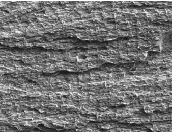
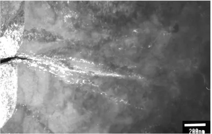
3.1 Zr2.5%NbFigure 1 below shows the typical appearance of a DHC fracture surface in Zr2.5Nb. This
Figure 1. The typical appearance of a DHC fracture surface in Zr2.5Nb. 200x.
is a fracture surface from one of the other Zr2.5Nb specimens tested in Studsvik, The direction of crack growth is to the right in the figure. It is clear from the picture that the crack propagates on different planes separated by nearly vertical faces. The arc shaped features running mainly perpendicular to the crack growth direction are the so-called striations. The striations were initially associated with jumps in the crack length
5
associated with the failure of a brittle hydride in front of the crack. This picture had some support in observations of jumps in potential drop values when crack growth was monitored by that method [17]. This picture was reinforced further when Shek et. al. [18] also correlated potential drop jumps with acoustic emissions. However Shek et. al. also noted that the correlation between physical crack jumps and acoustic emission signals almost disappeared when striation spacing became smaller than about 30 µm. Under those conditions the hydrides in front of the crack probably only fractures over a part of the specimen width and then cracks sideways across the width. In the present case with a striation spacing of about 20-25 µm it is thus probable that growth has occurred by such a sideways motion. This unfortunately also may have implications on the possibility to observe crack tip hydrides in the TEM. If the cross section happens to be located where the crack has just passed in its sideways motion there will be no hydride at the tip of the crack.
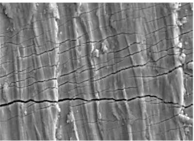
Before the sectioning of the specimen the external surfaces of the specimen were examined in order to locate the exact position of the crack tip. During this examination it was observed that there were numerous fine cracks on the surface. Examples of these fine cracks can be seen in Figure 2 from the outer side of the specimen. It is probable that
Figure 2. Fine cracks observed in association with the main crack. 1000x.
these cracks have formed in connection with the growth of the main crack. On the inner surface a pattern of these fine cracks seemed to emanate from the tip of the main crack in about ± 30° angle to the crack plane. The presence of these cracks is taken as an
6
indication that part of the electrolytically applied hydride layer had not been completely dissolved during the homogenization treatment.
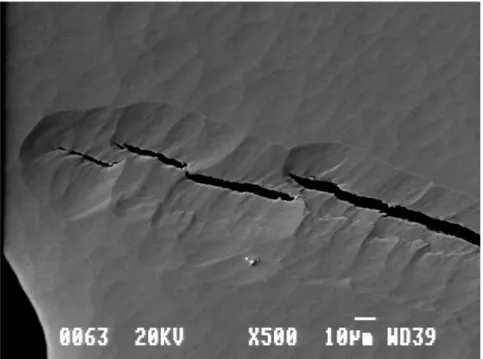
Despite the fact that 9 different specimens were prepared no successful foil with a thin area in the vicinity of the crack tip was obtained. Figure 3 shows one of the foils with a crack tip observed in SEM.
Figure 3. A crack tip as observed in SEM. 500x.
To the left in the picture we see the edge of a big hole. Ideally some further ion beam etching would make the area around the crack tip thin enough to be electron transparent. Unfortunately this particular specimen was lost during handling. The picture illustrates a couple of interesting features. It can be seen how the crack has grown on different planes with unbroken ligaments between in this particular cross section. At a later stage of crack growth these ligaments will of course be broken. Another interesting feature of the figure is the unevenness of the surface caused by the ion beam etching. It is
particularly interesting to see how the unevenness has been influenced by the crack. Similar features could be seen on all the foils after ion beam thinning.
A few of the foils were also observed in a FEG-SEM. Figure 4 shows a picture where the backscatter detector has been used. In that way any hydrides will be seen in a somewhat darker contrast than the matrix while the topography of the type seen in Figure 3 gives a weak contrast. Two hydrides can be seen in the picture. The one in the
7
lower left corner has a length of about 5 µm while the one in the middle has a size of somewhat less than 2µm.
Fig 4. The surface of one of the foils as observed in SEM. 1000x.
The size of the hydrides seen in cross section is interesting in view of the fact that the hydrides observed in TEM were generally much smaller, at most about 1 µm in length.
The microstructure in Zr2.5Nb is quite complex and it is diffcult to get a clear TEM picture of the microstructure. A typical example is shown in Figure 5.
Figure 5. The microstructure in Zr2.5Nb. A hydride can be seen in the middle of the figure. x80k.
The hydride seen in the middle of Figure 5 is typical of the hydrides observed in the specimens prepared. Due to the complexity of the microstructure, probably including
8
the presence of Nb rich β-phase it was impossible to evaluate the recorded diffraction patterns with regard to the form of the hydride phase. In most cases the diffraction spots seemed to fit better with the γ phase than the δ . On the other hand the (110) reflections unique to the γ phase [11] were never observed so it seems most probable that the hydrides are of the δ type.
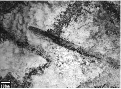
In one of the specimens a number of cracks emanated from the central hole. Figure 6 shows a dark field picture of some streaks starting at the tip of one of those cracks. Unfortunately the diffraction spot used for the dark field imaging does not correspond to any plane in any hydride so it is uncertain what these streaks actually represent. It is not even certain that this crack tip is the tip of the DHC crack. It may well have been formed in connection with the specimen preparation. However it is possible to speculate that what is seen in the picture may be the memory of intense shear deformation of the type proposed by Gregoriev as associated with DHC growth [7].
Figure 6. A dark field image of streaks emanating from a tip of a crack. x50k.
3.2 Zr-4
3.2.1 SEM examination.
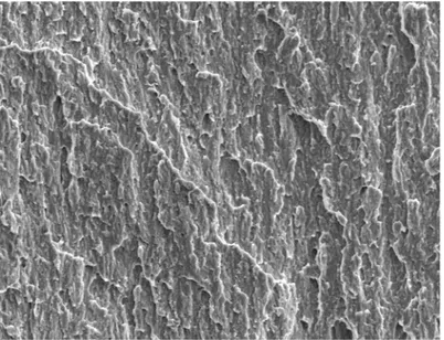
On one Zr-4 specimen the fracture surface was examined. A typical view of the DHC fracture surface can be seen in Figure 7. The direction of crack growth is from bottom to top in the figure. In comparison with Figure 1 from the Zr2.5Nb specimen it can be noted that there are no striations on this fracture surface. This perhaps indicates that the DHC crack growth in cladding tube is a more continuous process than in the Zr2.5Nb pressure tube material.
9
Figure 8 shows the surface of the Zr-4 specimen in which subsequently several metallographic cross sections were examined.
Figure 7. The DHC fracture surface on a Zr-4 specimen. x500.
10
The plastic zones formed when the specimen was loaded for DHC testing are clearly visible. It is also possible to measure a crack opening displacement value of 25 µm. The actual DHC crack is more narrow and the crack tip is located about 1.07 mm from the blunted tip of the fatigue crack. This and subsequent values of the location of the crack tip were measured by moving the specimen with the Y control knob of the specimen stage and reading the micrometer attached to the knob. The edge of the specimen was used as a reference point.
The specimen was first ground down to a depth of 0.05 mm. The depth was evaluated from the width of the flat surface produced by the grinding. A first polishing was done with 0.4 µm OP-S silica suspension. However the surface layer was apparently too cold worked to give any good images in either of the secondary electron or backscattered electron image modes. Therefore a light etching was performed in order to remove the cold worked layer. In the figure below a secondary electron (SE) image of the crack tip is shown side by side with a back scattered electron (BE) image of the same area.
Figure 9. The crack tip at a depth of 0.05 mm. The SE image to the left and the BE image to the right. 5000x.
If there are hydrides present they are expected to give a darker contrast than the zirconium matrix in the BE image. On that basis one might conclude that the crack faces at the crack tip consist of hydride and that there are two hydride plates in front of the crack tip. This is of course exactly the type of structure expected at the crack tip according to classical theories of DHC.
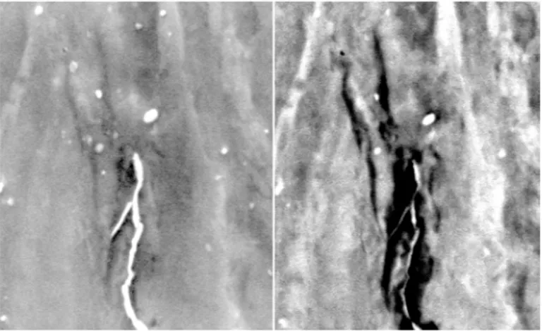
The next depth examined was 0.162 mm. The specimen was first examined after a light etch in the same way as at the previous depth. A composite picture with a SE and a BE image is shown i Figure 10.
11
Figure 10. The crack tip at a depth of 0.162 mm. In the SE image to the left the crack is seen as a light streak. There seems to be a bridge of metal between the ultimate crack tip and the main crack. 5000x.
The structure seen in Figure 10 is basically similar to the structure seen in Figure 9. There is considerable dark contrast along the crack and also extending beyond the tip of the crack indicating the presence of hydrides. However when the specimen was etched for hydrides there was no response to the etching with regard to hydrides. It should be noted that another specimen known to contain hydrides was etched at the same time and in that specimen the hydrides became quite visible after etching. On the basis of this observation there must be some doubt that the dark contrast in the BE image is actually due to the presence of hydrides.
A third section was done at a depth of 0.19 mm. A composite SE-BE picture is shown as Figure 11.
12
The microstructure is basically similar to that seen in the previous two figures with a dark contrast layer along the crack faces and plates of dark contrast extending from the tip of the crack.
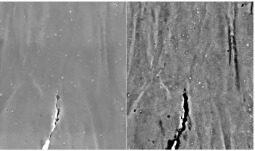
A fourth cross section att a depth of 0.235 mm was also examined. The composite picture, Figure 12, shows that there is in this case no contrast extending beyond the crack tip.
Figure 12. The crack tip at a depth of 0.235 mm. 2000x.
Two plate-like features can be seen in the upper right corner of the figure. It is also interesting to note that there are lots of other darkish features elongated in the direction of crack growth. These features are tentatively interpreted as belonging to the cold worked stress relieved microstructure of the material. The question which arises is whether or not the darkest features also are a result of this high dislocation density structure. The absence of any hydride etching response in cross section 2 supports such an interpretation. On the other hand the fact that the darkest features are observed exactly where we would expect hydrides to be present supports the interpretation that they are in fact hydrides. The absence of hydride plates ahead of the tip in cross section 4 can be understood if we assume that the test was interrupted at a time when the tip in this cross section just had made a jump. With this interpretation our observations tend to support the classical DHC theory rather than the hydrogen enhanced localized shear theory.
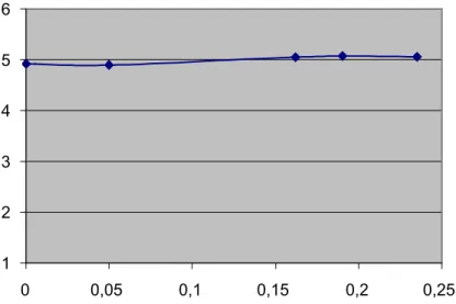
Figure 13 shows the position of the crack front at the five locations where it was measured.
13 1 2 3 4 5 6 0 0,05 0,1 0,15 0,2 0,25
Figure 13. The position of the crack front at the five depths where it was measured. Both axes are graded in mm.
This shape of the crack front is quite surprising. On all other specimens the front has had a typical thumb nail shape where the front near the surface has lagged behind the inside with typically about 0.3 – 0.5 mm. The question is whether or not this indicates a problem with doing the flat cross section in the way we have done. It is not immediately obvious what this problem might be.
3.2.2. TEM examination.
After the last examination of the cross section the area containing the crack was cut out of the ring specimen and thinned down mechanically from both sides. Final thinning with the aim of obtaining a thinned area at the tip of the crack was performed by ion milling. Figure 14 shows one example of a crack tip observed in the thin foil where a hydride is located at the tip. The picture is a dark field image taken with the (200) reflection of delta hydride. Unfortunately the quality of the diffraction pattern did not permit any good identification of directions in the picture. However the <200> direction in the hydride coincided with the 10 1 0 of the matrix.
14
Figure 14. A dark field image of hydrides in association with the tip of a crack. 30000x.
4. Discussion.
The purose of the present investigation was to determine if the mechanism of DHC is brittle failure of hydrides precipitated at the crack tip or if it is hydrogen enhanced localized shear which causes the cracking. Unfortunately the investigation has not resulted in a clear answer. One of the reasons is that it has not been possible to prepare a good crack tip specimen of any of the two different specimens which were available. A contributary factor is that in both the specimens the microstructure is very complex. It would probably have been much simpler if the investigation had been possible to carry out on fully recrystallized material. However no such specimen was available. But even in recrystallized Zircaloy difficulties can be expected since the KIH for DHC growth is
as high as about 13 MPa m [19], a stress intensity level where considerable plastic strain will be expected at the crack tip in recrystallized Zircaloy.
The best indication for the mechanism is the result of the cross sections of stress
relieved Zircaloy examined in SEM. The microstructure observed there seems to consist of a hydride rim along the crack flanks and hydrides precipitated ahead of the crack. This is consistent with the classical mechanism for DHC: However the identification of the microstructural features assumed to be hydrides is not clear. When one of the specimens was eteched for hydrides there was no response to the etching. This might be an indication that the dark features in the back scattered electron pictures identified as hydrides may be something else, perhaps areas with a very high density of dislocations.
15 1. Lundholm, L., et al.
Secondary fuel failure crack propagation mechanisms.
in Enlarged Halden Programme Group Meeting. 1993. Storefjell, Norway: Institutt for Energiteknikk, OECD Halden Reactor Project., pp.
2. Armijo, J.S.
Performance of failed BWR Fuel.
in 1994 Topical Meeting on Light Water Reactor Fuel Performance. 1994. West Palm Beach, FL.: American Nuclear Society, pp.
3. Edsinger, K., Davies, J.H., and Adamson, R.B.
Degraded fuel cladding fractography and fracture behavior.
in Zirconium in the Nuclear Industry: Twelth International Symposium. 1998. Toronto: American Society for Testing and Materials, pp. 316-399
4. Edsinger, K., Vaidyanathan, S., and Adamson, R.
On the mechanism of axial splits in failed BWR fuel rods.
in Ninth International Symposium on Environmental Degradation of
Materials in Nuclear Power Systems--Water Reactors. 1999. Newport
Beach: Minerals, Metals and Materials Society/AIME, pp. 1191-1199
5. Northwood, D.O. and Kosasih, U.
Hydrides and delayed hydrogen cracking in zirconium and its alloys.
International metals reviews, 1983. 28(2): pp. 92-121.
6. Rudling, P.
Secondary degradation mechanisms - a theoretical approach to remedial actions.
SKI, 2000, SKI Report 00:32.
7. Grigoriev, V. and Josefsson, B.
On the mechanism of Zircaloy axial cladding splits.
Journal of Nuclear Materials, 1998. 257: pp. 99-107.
8. Birnbaum, H.K.
16
in Hydrogen Effects on Material Behavior. 1989. Moran, Wyoming: TMS, pp. 639-658
9. Grigoriev, V. and Pettersson, K.
On the indications of shear fracture at the tip of an axial notch in Zircaloy cladding.
in Ninth International Symposium on Environmental Degradation of
Materials in Nuclear Power Systems--Water Reactors. 1999. Newport
Beach: Minerals, Metals and Materials Society/AIME, pp. 1177-1182
10. Grigoriev, V., et al.
A pin-loading tension test for evaluation of thin-walled tubular materials.
Scripta Metallurgica et. Materialia, 1995. 33: pp. 109-114.
11. Cann, C.D. and Sexton, E.E.
An electron optical study of hydride precipitation and growth at crack tips in zirconium.
Acta Metallurgica, 1980. 28: pp. 1215-1221.
12. Grigoriev, V. and Jakobsson, R.
IAEA Co-ordinated research program: "Round Robin" on measuring the velocity of delayed hydride cracking (DHC)
SKI, 1999, SKI Rapport 99:39.
13. Thomas, L.E.
Private communication. 1998.
14. Grigoriev, V. and Jakobsson, R.
Application of the pin-loading tension test to measurements of delayed hydride cracking veolocity in Zircaloy cladding.
SKI, 2000, SKI Report 00:57.
15. McMinn, A., Darby, E.C., and Schofield, J.S.
The Terminal Solid Solubility of Hydrogen in Zirconium Alloys.
in Zirconium in the Nuclear Industry: 12th International Symposium. 2000. Toronto, Canada, pp. 173-194
17
16. Zuzek, E., Abriata, J. P., San-Martin, A., Manchester, F. D.
The H-Zr (Hydrogen-Zirconium) system.
Bulletin of Alloy Phase Diagrams, 1990. 11: pp. 385-395.
17. Simpson, L.A. and Puls, M.P.
The effects of stress, temperature and hydrogen content on hydride-induced crack growth in Zr-2.5 pct Nb.
Metallurgical Transactions, 1979. 10A: pp. 1093-1105.
18. Shek, G.K. and et. al.
Hydride morpholgy and striation formation during delayed hydride cracking in Zr-2.5% Nb alloy.
Journal of Nuclear Materials, 1996. 231: pp. 221-230.
19. Efsing, P. and Pettersson, K.
The influence of temperature and yield strength on delayed hydride cracking in hydrided Zircaloy-2.
in Zirconium in the Nuclear Industry: Eleventh International Symposium. 1995. Garmisch-Partenkirchen: ASTM, pp. 394-404