Eds.: H.A. Mang, F.G. Rammerstorfer, J. Eberhardsteiner
Elastic-Plastic Deformation of a Nuclear Fuel Cladding Specimen
under the Internal Pressure of a Polymer Pellet
O. Dufourneaud and A. G. Varias*
Materials Science, Technology and Society Malmö University, SE-205 06 Malmö, Sweden
e-mail: andreas.varias@ts.mah.se
V. Grigoriev, R. Jakobsson and D. Schrire
Studsvik Nuclear AB, SE-611 82 Nyköping, Sweden e-mail: slava.grigoriev@studsvik.se
Key words: reactivity initiated accident, nuclear fuel
Abstract
During the operation of light water reactors, corrosion of nuclear fuel cladding results into the generation of hydrogen. With operation time increase, the hydrogen concentration in the cladding may exceed its terminal solid solubility and brittle zirconium hydrides may precipitate. Indeed hydrides are present in high burnup fuel cladding, which is therefore more susceptible to failure.
The Expansion Due to Compression (EDC) test has been developed for the study of irradiated and hydrided cladding failure, under conditions of pellet cladding mechanical interaction, which are expected during a reactivity initiated accident (RIA) or an in-pile test. During the EDC test, a piece of cladding tube is circumferentially loaded in tension due to the expansion of a polymer pellet, axially compressed inside the tube.
A finite element simulation of the EDC-test is presented. The objective of the study is: (i) to understand the deformation of the cladding, during the experiment, including the effect of cladding material properties, and (ii) to provide information, necessary for the development of failure criteria. The distributions of important field quantities with respect to the damage of the cladding are derived together with the evolution of their maximum values, during loading. It is shown that, before cladding yielding as well as after substantial plastic deformation, the radial displacement, on the external surface, and the total energy per unit volume, when appropriately normalized, vary along the cladding axis according load-independent distributions. This characteristic of cladding deformation is used for the development of failure criteria.
1 Introduction
During the operation of light water nuclear reactors, fuel cladding corrosion results into the development of an oxide layer, on the external surface, and the introduction of hydrogen into the metal (Zr+2H2O→ZrO2+2H2). Initially hydrogen is in solid solution and diffuses towards regions of low
concentration, high hydrostatic stress and low temperature. However, with increasing time of reactor operation, the hydrogen concentration may exceed its terminal solid solubility and brittle zirconium hydrides may precipitate. Indeed hydrides are present in high burnup fuel cladding, which is therefore more susceptible to failure, depending on hydride volume fraction and existing defects on the oxide layer.
The hydride-induced embrittlement results from the simultaneous operation of several coupled processes, namely, hydrogen diffusion, hydride precipitation, non-mechanical energy flow, and material deformation. The embrittlement may also lead to delayed hydride cracking, a subcritical crack growth mechanism, which allows crack propagation to proceed in a discontinuous fashion; a complete crack growth cycle includes stress-directed diffusion of hydrogen towards the crack tip, hydride formation and fracture. A mathematical model has been presented recently [1]-[2], which takes into account the coupling of all the above mentioned physical processes as well as hydride fracture. The model is based on the thermodynamic theory of irreversible processes and takes into account hydrogen thermal transport (Sorét effect). A finite element implementation of this hydride-induced embrittlement model has been used for the simulation of delayed hydride cracking initiation under constant temperature and K-field dominance as well as under temperature gradient, expected in the fuel cladding, during reactor operation [2]-[3].
Hydride-induced embrittlement of nuclear fuel cladding is also important, under narrow power pulse conditions in a reactivity initiated accident (RIA) [4]-[6]. Under RIA-conditions, overheating could produce pellet cladding mechanical interaction, due to both pellet thermal expansion and the expansion of fission gases (Xe, Kr) in the fuel pellet, and cause cladding failure.
Besides the in-reactor experiments, effort has been put into the development of mechanical tests, which reproduce the high strain rates, expected under RIA conditions. For example, high-pressurization-rate burst tests have been developed [7], in order to mechanically simulate the expansion of fuel cladding during a reactivity initiated accident. The expansion due to compression (EDC) test is such a purely mechanical testing technique [8], which produces pellet cladding mechanical interaction, under high strain rate. During the experiment, a pair of pistons compresses a polymer pellet, which is placed inside a fuel cladding tube. The diameter of the pellet increases, leading to development of contact pressure on the internal surface of the tube. The part of the tube, which is in contact with the pellet, suffers relatively high tensile hoop stress. Due to the small size of the specimen, the test allows the study of cladding performance at locations of relatively high hydride content and the efficient utilization of limited amounts of irradiated cladding material available for testing.
A finite element simulation of the EDC-test is discussed in the present paper. The objective of the study is to understand the deformation of the cladding, during the experiment, and to provide information, necessary for the development of failure criteria. Additional information are given in [9].
2 Mathematical Description of the EDC-test
In the present analysis, the polymer pellet has length equal to 10mm and radius equal to 4.175mm. The zirconium alloy cladding tube is twice as long and has external radius, R , equal to 4.825mm and wall
thickness t0=0.65mm. No initial gap between the cladding and the pellet is considered. The polymer
pellet is assumed to be in the middle of the cladding during the application of the loading. Such an assumption may not be rigorously satisfied in the actual experiment, because only one of the pistons is moving, during loading. However, this deviation from symmetry is not expected to affect the deformation of the cladding in the region of contact with the pellet. There, local symmetry is expected to be valid with respect to the mid-plane of the pellet. The deformation of the cladding and the pellet are also symmetric with respect to their common axis.
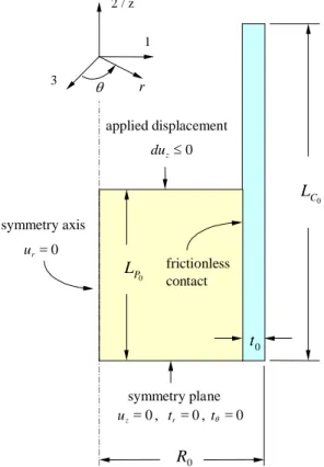
0 C L 0 P L 0 t 2 / z 1 3 r θ frictionless contact symmetry axis 0 = r u symmetry plane 0 , 0 , 0 = = = t tθ uz r 0 R applied displacement 0 ≤ z du
Figure 1: Geometry and boundary conditions for the finite element simulation of the pellet cladding mechanical interaction, produced by the EDC-test. The origin of the coordinate systems is on the
pellet/cladding mid-plane (i.e. the symmetry plane).
The geometry, used in the finite element simulation, is shown in Figure 1 together with the boundary conditions. The symmetries with respect to the pellet/cladding axis and the mid-plane require the consideration of only one quarter of the axial section of the pellet and the cladding. Therefore L andP0
0
C
L are the half-lengths of the pellet and the cladding, respectively. Cartesian, (x1, x2, x3), and
cylindrical, (r, θ, z), coordinates are considered. x2/z is the symmetry axis and (x1 x3) is the symmetry
plane, i.e. the pellet/cladding mid-plane. Note that, although not shown in Fig. 2, the origin of the coordinate system is on the symmetry plane.
The loading is applied by axial displacements, prescribed on the top pellet boundary, which result into the reduction of the length of the pellet and the development of compressive stresses in the pellet. Due to axial symmetry and material cohesion, the radial displacement, ur, is equal to zero along the
symmetry axis. On the symmetry plane at z=0, the axial displacements, u2, and the tangential traction,
The zirconium alloy cladding was assumed to be elastic-plastic. Young’s modulus, E, and Poisson’s ratio, ν, were taken equal to 97000 MPa and 0.4 respectively. For the plastic deformation, J2-flow
theory was considered with power-law isotropic hardening:
( )
p n p H 1 0 0 1 + = = ε ε σ ε σ , (1) where σ and εpare Mises effective stress and the accumulated effective plastic strain, respectively. Also σ0 is the initial yield stress in tension, ε0 is a reference strain, equal to the elastic strain at yielding initiation in simple tension, and n is the hardening exponent. Calculations have been performed for hardening material with σ0 equal to 600MPa and n equal to 7.76 as well as for
non-hardening material, (1/n=0), with σ0 equal to 400, 600 and 800MPa. Note that the hardening exponent
was derived from an ultimate tensile stress, in a simple tension test, equal to 780MPa. Thus the effect of irradiation on cladding deformation can be taken into account implicitly, by varying yield stress and hardening. Hardening is also affected by hydride precipitation [10]. However, in nuclear fuel cladding, hydrides precipitate mainly next to the oxide layer, on the water-side of the cladding. Therefore an appropriate simulation should take into account the non-homogenous hydride distribution.
The properties of the pellet polymer were calculated, by analyzing pellet compression tests, which were performed at room temperature in Studsvik Nuclear. The pellet material was assumed to be elastic-plastic. Young’s modulus, EP, and Poisson’s ratio, νP, were derived to be equal to 594 MPa and
0.474, respectively. Plastic behavior was again simulated, by using J2-flow theory and isotropic
hardening. It was found that a combination of Johnson-Cook and linear hardening laws provide the best fitting to the experimental data:
( )
( )
p N P p K H ε σ ε σ = = 0 + , εp ≤0.05, (2a)( )
= 0 +(
0.05)
+(
0.05)
1(
−0.05)
= N N− p P p KN K H ε σ ε σ , εp ≥0.05. (2b)The coefficient K and the hardening exponent N are equal to 19MPa and 0.22, respectively. The yield stress in compression, σP0, was derived to be equal to 6.4MPa.
No rate effects of the pellet material were considered. Indeed, the duration of the EDC-test is a fraction of a second (e.g. 0.05 to 0.2 s). Therefore, the relaxation of the material is negligible. The test, for a certain loading rate, could be adequately simulated, by considering the stress-strain curve of the polymer, for the loading rate under consideration. In order to estimate the effect of polymer yield stress variation, due to different loading rates, an additional calculation was performed with polymer yield stress by 20% smaller than that used in all other calculations. No variation on the hardening was assumed. The normalized distributions of cladding radius change and total energy density, along the symmetry axis, were identical for both yield stress values of the polymer. Therefore, the results on the deformation of the cladding do not depend on the rate-effects of the polymer, for the temperature and the rates under consideration.
For the finite element calculations, ABAQUS/Standard (version 6.1) and the ‘hard’ contact model were used. Then, no pressure was applied while surfaces were not in contact, and any level of pressure could be applied, once contact was established. CAX4R elements without twist were selected, which are 4-node bilinear axisymmetric solid elements. 100x85 elements of equal size were used in the pellet and 400x26 equal-size elements were used in the cladding.
3 Derivation of Critical Total Energy Density
The deformation of the cladding depends on zirconium alloy elastic-plastic properties, cladding geometry and distribution and level of applied loading. The area over which contact pressure is applied and consequently the distribution of applied loading depend on the initial pellet length, L . AP0
measure of loading is the ratio of the length of the deformed pellet over its initial value, LP LP0. Note that, given the pellet properties, including hardening, LP LP0 has a one-to-one relation with the traction, applied by the pistons. However, LP LP0 depends on pellet’s properties and consequently it
generally provides a different cladding deformation status for different pellet material. An alternative loading measure, is the ratio of the change of the cladding external radius over its initial value at the mid-plane, ∆R R0. Note that ∆R R0 provides the engineering hoop-strain on the external surface of
the cylinder at the mid-plane and it can be measured during the performance of the experiment. Therefore cladding deformation depends mainly on cladding material parameters, (σ0/E, ν, n), on
geometry characteristic lengths, (t0 R0 , LC0 R0, LP0 R0), and loading,∆R R0 . Note that, if the pellet is made of a nearly incompressible material with low yield stress, the deformation of the cladding is nearly independent of pellet material properties.
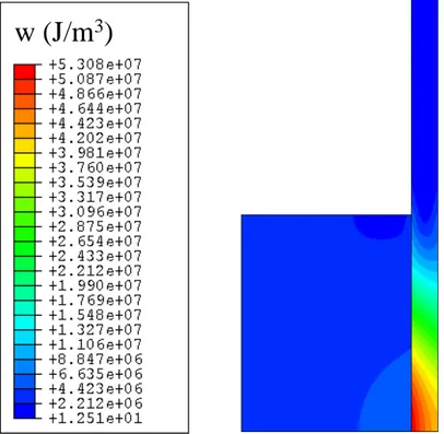
w (J/m
3)
Figure 2: Distribution of the total energy density, w, for a hardening zirconium alloy with MPa
600
0=
σ , at ∆R R0 =6.0%.
In the following emphasis will be placed on the energy, which is injected in the specimen, as well as on the deformed cladding profile. Note that, currently, experimental investigations are performed to derive failure criteria, based on energy density [8]. Information on the distribution of other field quantities as well as the evolution of their maximum values with loading are discussed in [9].
Figure 2 shows the distribution of total energy density, w, (i.e. the sum of strain energy density and plastic work per unit volume), for a hardening cladding with yield stress equal to 600 MPa, at
% 0 . 6
0=
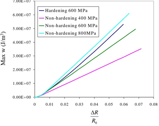
∆ RR . Note that the contribution of the plastic work per unit volume is dominant, being an order of magnitude larger than the strain energy density. The maximum develops at the mid-plane and the internal cladding surface, where the cladding is deformed at most. The effects of cladding hardening and yield stress on the evolution of the maximum value of w with ∆R R0are presented in Figure 3. For a given value of ∆R R0, the reduction of hardening and yield stress leads to the reduction of the maximum value of w.
0
R
R
∆
Ma
x
w
(
J/m
3)
0.00E + 00 1.00E + 07 2.00E + 07 3.00E + 07 4.00E + 07 5.00E + 07 6.00E + 07 7.00E + 07 0 0.01 0.02 0.03 0.04 0.05 0.06 0.07 0.08 Hardening 600 M Pa Non -h ardening 40 0 M Pa Non -h ardening 60 0 M Pa Non -h ardening 80 0M PaFigure 3: Variation of the maximum value of the total energy per unit volume, w , with cladding straining, given by ∆R R0 .
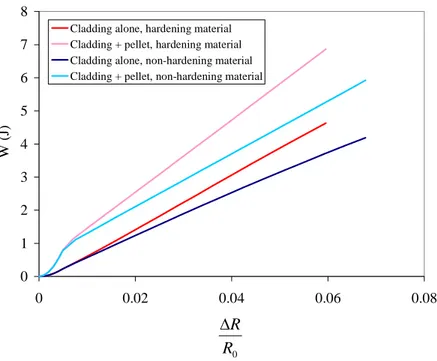
Figure 4 shows the injected energy, W, in the cladding and the pellet as well as in the cladding alone. The curves correspond to hardening and non-hardening cladding with yield stress σ0 =600MPa. It is emphasized that the energy, which is dissipated or stored in the pellet, is an appreciable part of the total injected energy. For example, at ∆ RR 0 =6.0%, the total injected energy is 6.9J, when the cladding hardens. In this case, the energy injected in the pellet is equal to 2.2J, i.e. one third of the total injected energy. At smaller cladding strains, the fraction of the energy, dissipated/stored in the pellet, is even larger. For example, at ∆ RR 0 =2%, the total energy is about equal to 2.6J and the pellet part is about equal to 1.1J. Similar values are derived for non-hardening cladding. During the performance of the EDC-test, the energy, which is injected in both pellet and cladding, is easily measured from the displacement of the piston and the applied load. It is however very important for the development of failure criteria to subtract the part of the energy, which dissipated or stored in the pellet, since it does not contribute to the damage of the cladding.
0 1 2 3 4 5 6 7 8 0 0.02 0.04 0.06 0.08
Cladding alone, hardening material Cladding + pellet, hardening material Cladding alone, non-hardening material Cladding + pellet, non-hardening material
W ( J) 0 R R ∆
Figure 4: Variation of injected energy in pellet/cladding and cladding alone with cladding straining, given by ∆R R0 . The cladding yield stress is 600MPa.
3.1 Axial Distributions of Cladding Radius Change and Total Energy Density – Development of a Failure Criterion
Cladding external radius is a quantity, which is measured easily. Its distribution along the symmetry axis provides information on the elastic-plastic deformation of the cladding and it could facilitate the development of cladding failure criteria. Indeed, Grigoriev, Jakobsson and Schrire [8] have measured the distribution of the permanent change of cladding external diameter along its symmetry axis, in the unloaded condition after the performance of experiments, which did not result into the fracture of the cladding. Subsequently, they assumed a linear relation between total energy density and external radius change or equivalently the respective engineering hoop strain. Based on this assumption, they provided estimates on the critical total energy density for the cases of cladding failure.
In the present section, the axial distributions of external radius change and total energy density in the cladding as well as their dependence on applied loading will be presented. The validity of a linear relation between total energy density and external radius change will be also investigated.
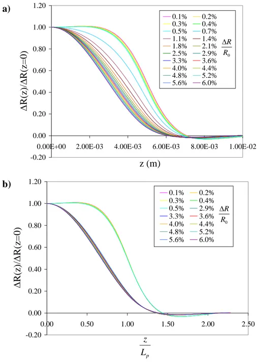
Figure 5a shows the axial distribution of cladding radius change for various levels of applied loading, expressed by ∆R R0 . The distributions correspond to the case of hardening cladding. The radius
change has been normalized by its value at the symmetry plane. Note that the distributions before cladding yielding, i.e. at ∆ RR 0≤0.5%, differ only slightly. Also the distributions seem to converge at relatively high plastic deformation, i.e. ∆ RR 0 ≥3%. On the other hand, the respective distributions at the initial stage of plastic deformation vary significantly with loading. The axial distribution of any field quantity is expected to depend on the size of the contact surface, where internal pressure is applied on the cladding. It is therefore expected that the axial distributions of field quantities depend on the current pellet length, L . For this reason P ∆R
( )
z / R∆( )
0 has been plotted again as a function ofP L
error, onto two lines, one for ∆ RR 0 ≤0.5% and another for ∆ RR 0≥3%. Therefore the axial distribution of ∆R
( )
z / R∆( )
0 vs. z /LP does not depend on the level of applied loading for% 5 . 0
0 ≤
∆ RR and ∆ RR 0 ≥3%, in the case of hardening cladding with yield stress equal to 600 MPa. The load-independent axial distributions have been also derived for total energy density as well as for non-hardening cladding material [9].
z (m)
∆
R(
z)
/∆
R(
z=
0
)
R0 R ∆ -0.20 0.00 0.20 0.40 0.60 0.80 1.00 1.200.00E+00 2.00E-03 4.00E-03 6.00E-03 8.00E-03 1.00E-02 0.1% 0.2% 0.3% 0.4% 0.5% 0.7% 1.1% 1.4% 1.8% 2.1% 2.5% 2.9% 3.3% 3.6% 4.0% 4.4% 4.8% 5.2% 5.6% 6.0%
a)
b)
∆R(z)
/∆
R(z=
0)
pL
z
0 R R ∆ -0.20 0.00 0.20 0.40 0.60 0.80 1.00 1.20 0.00 0.50 1.00 1.50 2.00 2.50 0.1% 0.2% 0.3% 0.4% 0.5% 2.9% 3.3% 3.6% 4.0% 4.4% 4.8% 5.2% 5.6% 6.0%Figure 5: Axial distribution of the increase of the cladding external radius, ∆R
( )
z , normalized by its value on the symmetry plane, ∆R( )
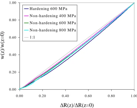
0 , vs. a) z-position in the deformed state and b) z LP. HardeningThe axial distribution of the total energy density, after significant plastic deformation, differs only slightly from the respective distribution of the cladding external radius change. Therefore:
( )
( )
0 w( )
( )
0 z w R z R ≅ ∆ ∆ . (3)The validity of equation (3) has been verified for all cladding material properties, under consideration. According to Figure 6, the maximum deviation varies between 2.9% for σ0 =400MPa (non-hardening material) and 6.9% for σ0 =600MPa (hardening material). The error is below 5% for all non-hardening cases, considered in the present study.
0.00 0.20 0.40 0.60 0.80 1.00 0.00 0.20 0.40 0.60 0.80 1.00 Harden in g 60 0 M Pa No n-h arden in g 40 0 M Pa No n-h arden in g 60 0 M Pa No n-h arden in g 80 0 M Pa 1 :1
∆R(z)/∆R(z=0)
w(z
)/
w
(z=0
)
Figure 6: Total energy density vs. external radius increase.
If the linearity assumption is used, then the critical total energy density, at cladding failure, could be calculated by considering the equality [8]:
ave cr ave cr R R w w ∆ ∆ ⋅ = , (4) where cr R
∆ is the external radius increase at the mid-plain, when failure occurs, and ave R
∆ is the
average external radius change. Note that ∆Rave can be estimated experimentally. The following procedure could be also applied:
(1) experimental measurement of the total injected energy, up to cladding failure, minus the elastic strain energy stored in the loading device,
(2) subtraction of the energy dissipated/stored in the pellet, by numerically deriving a diagram similar to that in Figure 4, and estimation of the average injected energy density in the cladding, wave,
(3) numerical derivation of the load-independent w
( ) ( )
z / w0 vs. z /LP curve as well as of the average value of w( ) ( )
z / w0 over the whole range of z /LP,(
w( ) ( )
z w0)
ave,(4) calculation of the critical total energy density in the cladding, wcr
( ave
(
( ) ( )
)
ave w z w w 0 = ). AcknowledgementsThe present study is part of the project on ‘Hydrogen Embrittlement and Fracture in Hydride Forming Metals’, which is financed by the Foundation for Knowledge and Competence Development (Project Grant Hög 2000, KK-Stiftelsen, Sweden). The project is performed with the cooperation of Studsvik Nuclear AB and Barsebäck Kraft AB.
References
[1] A.G. Varias, Mathematical Model for Hydrogen Diffusion, Energy Flow and Hydride Formation
in Zirconium under Stress, BR-04-10-98, Solid Mechanics Research Office, Athens, Greece
(1998).
[2] A.G. Varias, A.R. Massih, Hydride-induced Embrittlement and Fracture in Metals – Effect of
Stress and Temperature Distribution, Journal of the Mechanics and Physics of Solids, 50, (2002),
1469-1510.
[3] A.G. Varias, A.R. Massih, Simulation of Hydrogen Embrittlement in Zirconium Alloys under
Stress and Temperature Gradients, Journal of Nuclear Materials, 279, (2000), 273-285.
[4] T. Fuketa, H. Sasajima, Y. Mori, K. Ishijima, Fuel Failure and Fission Gas Release in High
Burnup PWR Fuels under RIA Conditions, Journal of Nuclear Materials, 248, (1997), 249-256.
[5] F. Lemoine, High Burnup Fuel Behavior related to Fission Gas Effects under Reactivity Initiated
Accidents (RIA) Conditions, Journal of Nuclear Materials, 248, (1997), 238-248.
[6] F. Schmitz, J. Papin, High Burnup Effects on Fuel Behaviour under Accident Conditions: the
Tests CABRI REP-Na, Journal of Nuclear Materials, 270, (1999), 55-64.
[7] M. Kuroda, K. Yoshioka, S. Yamanaka, H. Anada, F. Nagase, H. Uetsuka, Influence of
Precipitated Hydride on the Fracture Behaviour of Zircaloy Fuel Cladding Tube, Journal of
Nuclear Science and Technology, 37, (2000), 670-675.
[8] V. Grigoriev, R. Jakobsson, D. Schrire, Experimental Evaluation of Critical Strain Energy
Density for Irradiated Cladding under Simulated RIA Conditions, in Proceedings of ENS Topfuel 2001, Stockholm (2001).
[9] O. Dufourneaud, A.G. Varias, Elastic-Plastic Deformation of a Nuclear Fuel Cladding Specimen
under the Internal Pressure of a Polymer Pellet, PA-03-06-01, Malmö Univeristy, Malmö,
Sweden (2001).
[10] S. Arsène, J.B. Bai, Effect of Hydriding and Irradiation on the Mechanical Properties of Zircaloy