‘FALSE BAKKEN’ INTERVAL- SEDIMENT PATTERNS AND DEPOSITIONAL ARCHITECTURE AT THE FACIES BOUNDARY BETWEEN SILICICLASTIC MUDSTONES AND CARBONATES,
LODGEPOLE FORMATION, MISSISSIPPIAN IN THE WILLISTON BASIN, ND
Submitted by Joel Spansel
Department of Geosciences
In partial fulfillment of the requirements
Fort the Degree of Master of Science
Colorado State University
Fort Collins, Colorado
Spring 2020 Master’s Committee:
Advisor: Sven Egenhoff
Sally Sutton Joe Von Fischer
Copyright by Joel Parker Spansel 2020 All Rights Reserved
ii ABSTRACT
‘FALSE BAKKEN’ INTERVAL- SEDIMENT PATTERNS AND DEPOSITIONAL ARCHITECTURE AT THE FACIES BOUNDARY BETWEEN SILICICLASTIC MUDSTONES AND CARBONATES,
LODGEPOLE FORMATION, MISSISSIPPIAN IN THE WILLISTON BASIN, ND
The lateral facies transition on deep shelves between carbonates and siliciclastic mudstones is largely enigmatic. Based on detailed facies descriptions and interpretations, this study explores which processes have shaped the sedimentary rocks on both sides of this lithological divide, and adds to our understanding of processes operating on deep shelves in general. Both siliciclastic and carbonate rocks of the ‘False Bakken’ and ‘Scallion’ intervals of the lower Lodgepole Formation in the Williston Basin, ND, can be grouped into twelve facies: these facies are graded argillaceous mudstone (F1), massive
siliciclastic-argillaceous mudstone (F2a), massive calcareous-argillaceous mudstone (F2b), bioturbated pyrtitized bioclast-bearing mudstone (F3), lenticular mudstone (F4), bioclast-rich wavy mudstone (F5), siliciclastic siltstone (F6), glauconitic siltstone (F7), calcareous siltstone (F8), massive to bioturbated carbonate mudstone (F9), nodular skeletal wackestone (F10), and laminated skeletal packstone (F11). These facies are here presented in order of increasing grain size, carbonate content, and bioturbation from F1 to F11. They are arranged in three fining- and coarsening-upward units that can be identified
throughout the basin within the succession.
These twelve facies are interpreted to represent distinct processes on a low-inclined shelf system with carbonate occupying the proximal, and siliciclastic mudstones the distal portions of this transect. An overall decrease in energy is reflected from the proximal carbonate to distal siliciclastic facies in this sedimentary system. Nevertheless, most of the mudstone facies still reflect high energy processes operating within the distal portions of the basin; in fact, only one mudstone facies is interpreted to reflect suspension settling under tranquil conditions. Therefore, this study suggests that storm wave base is best placed within the distal siliciclastic mudstones instead of in the proximal carbonates. Carbonate
iii
mudstones, deposited above storm wave base but lacking tempestite deposition are therefore interpreted as having been subject to intense degradation of storm-derived bioclasts. A decrease in oxygen
concentration is inferred from proximal carbonates to distal siliciclastics as indicated by the decrease in size and type of burrows; yet, the presence of burrows within the most distal facies belt indicates that at least dysoxic conditions prevailed throughout the Williston Basin during the deposition of the ‘False Bakken’.
Three transgressions and regressions are identified within this succession based on laterally correlated facies patterns and indicate an overall increase in sea level from the beginning to the end of ‘False Bakken’ times. Sediment starvation occurred in the northeastern and/or southwestern portions of the basin as indicated by the presence of glauconitic siltstones and/or lenticular mudstones at various locations within the succession. However, a source of sediment input is interpreted to be located in the northwestern part of the basin based on a high abundance of detrital silt. In addition, a shift in the basin depocenter southwards from Bakken to lower Lodgepole times is reflected in this succession most likely mirroring an increase in subsidence south of Mountrail County during ‘False Bakken’ deposition.
iv
ACKNOWLEDGEMENTS
I would like to thank the SEPM Foundation for funding a portion of my research in pursuit of my master’s thesis. I also owe a special thanks to Sven Egenhoff for dedicating a substantial amount of his time to me throughout my entire time here at Colorado State University from teaching me about shale and carbonate sedimentology, to guiding me in my thesis work, and for always being an enjoyable person to work with and talk to. In addition, I would like to thank my committee members Dr. Sally Sutton and Dr. Joe Von Fischer for their insight and revisions and general support during my thesis work.
I owe a thanks to Heather Lowers at the USGS for providing both her expertise and SEM machine to allow me to collect data for my thesis work. I also would like to thank Kent Hollands at the NDGS Core Center for organizing the cores, obtaining samples for me, and transporting me to and from the core center during my time spent in North Dakota. I would also like to thank members of my research group, James Van Hook and Aleks Novak, for the fun times spent in and out of the office as well as for their help and useful input throughout my thesis work. Finally, I would like to thank all the other grad students in the department who made my time here in Colorado such an enjoyable and fun experience.
v
TABLE OF CONTENTS
ABSTRACT………..ii
ACKNOWLEDGEMENTS………..iv
LIST OF FIGURES………..vi
INTRODUCTION……….1
GEOLOGIC SETTING……….3
METHODS……….…………...6
FACIES ………...10
Siliciclastic Facies of the False Bakken ‘Interal’……...………...………..10
Carbonate Facies of the False Bakken ‘Interal’ …..………..23
Carbonate Facies of the Scallion ‘Interval’………24
FACIES ARCHITECTURE………33
DEPOSITIONAL MODEL……….39
DISCUSSION………..46
Facies in Siliciclastic Mudstones………..46
Carbonate-Shale Transitions………...47
Position of Storm Wave Base and Implications for Carbonate Facies Models………...49
Glauconite………..51
Oxygen Availability in the Water Column and Sediment during ‘False Bakken’ deposition…...53
CONCLUSIONS………..55
REFERENCES……….58
APPENDIX I: MEASURED SECTIONS………...64
APPENDIX II: THIN SECTION DESCRIPTIONS……….106
vi
LIST OF FIGURES
Figure 1: Stratigraphic Column………..…2
Figure 2: Regional Map of Core Locations and Structural Highs………..4
Figure 3a: Facies 1 and 2a in a thin section scan………14
Figure 3b: SEM image of facies 2a matrix………14
Figure 3c: Phycosiphon incertum isp. fecal strings in facies 2a………15
Figure 3d: Thin section scan of facies 2b……….15
Figure 3e: Cross-polarized image of agglutinated foraminifera………15
Figure 4a: Core image of F3……….19
Figure 4b: SEM image of F3 matrix……….19
Figure 4c: Plane-polarized image of Chondrites isp. in F3………..19
Figure 4d: Core image of brown F4 laminae………19
Figure 4e: Thin section scan with F4 laminae thickening and thinning laterally……….20
Figure 5a: Core image of F5 lamina within F3………..22
Figure 5b: Thin section scan of F5 lamina………22
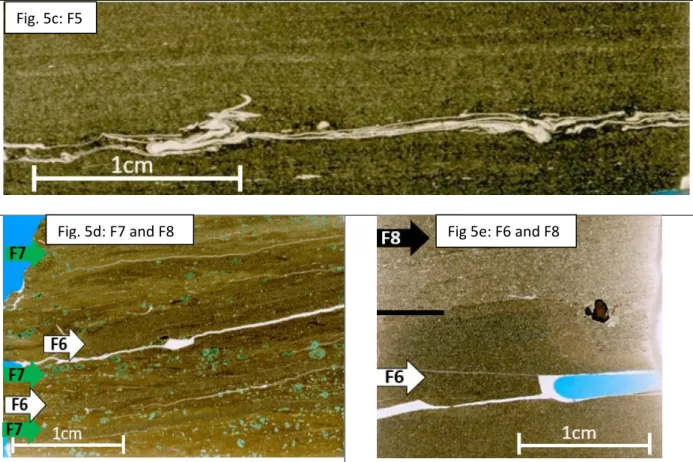
Figure 5c: Thin section scan of thin F5 lamina………23
Figure 5d: Thin section scan of F6 and F7 laminae………..23
Figure 5e: Thin section scan of F6 and F8 laminae………..23
Figure 6a: Core image of F9……….26
Figure 6b: Thin section scan of F9………26
Figure 6c: Core image of F10………...27
Figure 6d: Thin section scan of F10……….27
Figure 6e: Core image of F11………...27
Figure 6f: Thin section image of F11………27
Figure 7: Map with contacts between shales and carbonates for coarsening- and fining-upward units…..34
Figure 8: Cross-section from A to A’………..35
Figure 9a: Areal distribution of F1 laminae……….38
Figure 9b: Areal distribution F4 laminae………..38
Figure 9c: Areal distribution of F5 laminae………..38
Figure 9d: Areal distribution of F7 laminae………..38
Figure 10: Idealized depositional model………...40
Figure 11: General map of facies belts……….42
1
INTRODUCTION
The lateral facies transition from carbonates to adjacent siliciclastic mudstones in distal areas remains completely enigmatic and surprisingly underexplored. Most carbonate literature focuses on shallow-marine limestones, be it reefs (e.g., Hubbard et al. 1990; Pomar, 1991; Ritter and Grammer, 2017), lagoons (e.g., Colby and Boardman, 1989; Randazzo and Baisley, 1995; Beanish and Jones, 2002; Klostermann and Gischler, 2015), the shallow shelf (e.g., Nelson et al. 1988; Rankey, 2004), or a ramp system (e.g., Martin et al. 1996; Brandano and Corda, 2002; Pomar et al. 2004). The step from carbonate producing platforms to equivalent facies signatures in adjacent basins is not a far one, so calci-turbidites are similarly well-explored (e.g. Reijmer et al. 1991; Kenter, 1991).
In recent years, siliciclastic mudstones have also received significant attention (Schieber et al. 2007; Schieber and Southard, 2009; Schieber et al. 2010; Macquaker et al. 2010; Wilson and Schieber, 2014), and current-induced processes in these environments once believed to be entirely tranquil have been explored in great detail (e.g. Egenhoff and Fishman, 2013; Borcovsky et al. 2017; Li and Schieber, 2018). However, the intersection where these two rocks, the carbonates and the siliciclastic mudstones, meet has been severely underexplored (e.g. Burchette and Wright 1992). This is insofar surprising as many deep shelves in the world, in the Recent as well as in ancient examples, exhibit this particular transition. This study will therefore propose a model of how such a transition looks in the geological record, and how to unravel sedimentological details to characterize such a facies transition that is likely ubiquitous since carbonates started to form a distinct environment on many shelves worldwide in the Proterozoic (Grotzinger, 1989).
The main unit under study is the ‘False Bakken’, a siliciclastic mudstone succession intercalated into the lower portion of the Mississippian Lodgepole Formation; in addition, the underlying skeletal wackestones to packstones of the ‘Scallion’ interval are also assessed (Fig. 1; Mackie, 2013). Based on conodont biostratigraphy, deposition of the lower Lodgepole occurred during the Siphonodella crenulate
2
Zone in the Tournasian Stage and is suggested to have commenced prior to the Tournasian-Visean boundary, although the upper boundary is not well defined due to a lack of conodont data (Holland et al. 1987; Hogancamp and Pocknall, 2018).
Fig. 1: Stratigraphic column from the Devonian Bakken Formation to the Mississippian Charles Formation modified from Borcovsky et al. (2017). Conodont biozones from Hogancamp and Pocknall, (2018).
3
GEOLOGIC SETTING
Covering an area of 300,000km2, the Williston Basin is an intracratonic basin that extends across a large portion of North Dakota, the northwestern portion of South Dakota, the eastern portion of
Montana, and the southern portion of Saskatchewan and Manitoba in Canada (Gerhard et al. 1982; Kerr, 1988; Anna et al. 2010). Sedimentation, mainly controlled by sea level fluctuations and episodic, slow subsidence, began in the Cambrian and continued into the Quaternary with the accumulation of about 4,875m of sediments in the deepest section of the basin in northwestern North Dakota (Kerr, 1988; Gaswirth and Marra, 2015). A lack of thick siliciclastic sequences and abundance of carbonates in the Paleozoic indicate the basin was isolated from major orogenic events (Kerr, 1988; Gaswirth et al. 2013), although local structural highs such as the Billings Anticline, Burleigh High, Cedar Creek Anticline, Foster High, and Stutsman High are suggested to have been active highs during the late Devonian-early Mississippian (Ballard, 1963; LeFever and Crashell, 1991; Grover, 1996) in addition to other trends not formerly named (Novak and Egenhoff, 2019; Fig. 2). Paleogeographic reconstructions place the Williston Basin of North America just north of the equator at the end of the Devonian and early Mississippian (Scotese, 1994; Blakey, 2003).
The Mississippian Madison Group reaches a maximum thickness of 610m, conformably overlies the Bakken, and is comprised of carbonates and rare shales of the Lodgepole, anhydrite-bearing
carbonates of the Mission Canyon, and evaporites of the Charles Formations (Fig. 1; Carlson and Anderson, 1965; Kerr, 1988). Prior to deposition of the Lodgepole, the Bakken Formation was deposited from Late Devonian to Early Mississippian times (Holland et al. 1987). The Bakken reaches a maximum thickness of 43m and is composed of four units: a basal sand-rich unit, a lower and an upper shale member that are organic rich, and a coarse-grained middle member composed mostly of siltstone and some sandstone (Meissner, 1978; LeFever, 1990; Egenhoff and Fishman, 2013; Egenhoff, 2017).
4
Fig. 2: Location of 33 cores in the western portion of North Dakota. Both core numbers and relevent county names are displayed. Structural highs and anticlines present throughout the Williston Basin at various times. Modified from Novak and Egenhoff (2018) with additional structural highs from Ballard (1963).
The Lodgepole Formation reaches a maximum thickness of 270m in McKenzie County where it consists of mostly limestones with rare shale stringers and thins towards the margins where it is a fossiliferous and oolitic limestone (LeFever and Anderson, 1984; Montgommery, 1996; Stroud, 2011). The ‘Scallion’ Interval, composed of nodular skeletal wackestones and packstones, conformably overlies the upper Bakken shale member and represents a regression from late Bakken times (Gaswirth et al. 2013; Mackie, 2013; Borcovsky et al. 2017). One to three siliciclastic shales intercalated with carbonate
5
mudstones are informally known as the ‘False Bakken’ and represent an overall transgression from the ‘Scallion Interval’ (Montgommery, 1996; Kerr, 1988; LeFever, 1990; Hansen and Long, 1991; Mackie, 2013). The ‘False Bakken’ is suggested to have been deposited in distal areas on a low-inclined westward dipping carbonate platform and beautifully displays shale-carbonate transitions (Mackie, 2013). The carbonate unit overlying the ‘False Bakken’ does not have a specific name and is generally just referred to as being part of the “Lower Lodgepole Limestone” (LeFever and Anderson, 1984).
6 METHODS
Detailed sedimentological analyses were completed for 33 drill cores that penetrated the ‘False Bakken’ and ‘Scallion’ intervals of the lower Lodgepole Formation (Fig. 2; see Table 1). All cores are stored at the North Dakota Geological Survey (NDGS) Wilson M. Laird Core and Sample Library in Grand Forks, ND or at the U.S. Geological Survey (USGS) Core Research Center in Denver, CO. Detailed core descriptions on the millimeter to centimeter scale were made with the aid of a hand lens, tape measure, and hydrochloric acid to identify various facies and features. For the purpose of this paper, a facies is best classified as any lamina or bed that reflects a certain composition, grain size distribution, and depositional feature allowing it to be tied to a distinct depositional process.
Ultra-thin thin sections (~20um) were made both perpendicular (n=48) and parallel (n=9) to bedding, as compaction should not impact any depositional features preserved parallel to bedding (i.e., clay clasts and burrows). Additional thin sections (n=16) were borrowed from the USGS to further describe each facies. All thin sections were used for petrographic analyses to identify textures and compositions of various facies identified in core.
Point counting (n=300) was completed on thin sections (n=22) to determine the modal abundance of matrix versus silt grains, as well as the abundance of various grain types within the silt fraction (see Table 2). For other thin sections, modal abundances were determined with the aid of Baccelle and Bosellini (1965) visual diagrams. To determine the mean grain size of the silt-sized fraction of all siliciclastic facies, point counts (n=300) were completed on thin sections (n=26; see Table 3).
An FEI Quanta 450 FEG Scanning Electron Microscope (SEM) equipped with an energy dispersive spectrometer (EDS) at the USGS in Denver, CO, was used to analyze carbon-coated thin sections (n=7) with the most representative siliciclastic facies to identify very small structures and particles (e.g., clay clasts, biogenic grains, burrows, and organic matter; see Appendix III).
7
Table. 1: All wells with geographic locations and core storage locations.
Number Well # Well Name Latitude Longitude County Location 1 8251 USA #1-24 47.183926 -103.548139 Billings NDGS 2 18502 TEDDY 44-13TFH 47.111641 -103.415384 Billings NDGS 3 9426 FEDERAL #12-1 47.30137 -103.54544 Billings NDGS 4 12886 CONNELL #24-27 47.2567 -103.597082 Billings NDGS 5 7887 MEE USA #3-17 47.120931 -103.379412 Billings NDGS 6 10077/E385 FEDERAL 11-4 47.31096 -103.56845 Billings NDGS/USGS 7 B832 AL AQUITAINE BN 1-23H 47.194467 -103.568295 Billings NDGS/USGS 8 8638 SLATER #1-24 48.751046 -102.433563 Burke NDGS 9 20648 GROTE 1-21H 48.663157 -102.834024 Burke NDGS 10 19773 PRODUCER`S CORPORATION 159-94-17C-8-2H 48.590525 -102.85718 Burke NDGS 11 13167 SKARPHOL "D" #5 48.708913 -102.898789 Divide NDGS 12 17396 BLOOMING PRAIRIE 48.879255 -103.438098 Divide NDGS 13 19709 ROSENVOLD 1-30H 48.661666 -103.132496 Divide NDGS 14 12785 CARUS FEE #21-19 47.542727 -102.963685 Dunn NDGS 15 607 ANGUS KENNEDY #F32-24-P 47.711593 -102.522114 Dunn NDGS 16 22092 MHA 2-05-04H-148-91 47.667005 -102.310361 Dunn NDGS 17 20453 WALLACE 7-1H 47.213633 -102.635928 Dunn NDGS 18 21734 OLSON 12-139-104 A 1H 46.863048 -103.749957 Golden Valley NDGS
19 19917 MAUS 23-22 47.013434 -103.850932
Golden
Valley NDGS 20 24123 MARIANA TRUST 12X-20G2 47.71198 -103.131792 Mckenzie NDGS 21 12772 AHEL ET AL GRASSEY BUTTE #12-31 H3 47.485595 -103.234115 Mckenzie NDGS 22 29426 TETON 5-1-3TFSH 47.850828 -102.951089 Mckenzie NDGS 23 21966 FAIRBANKS 1-20H 47.558227 -103.551635 Mckenzie NDGS 24 17723 MILLER 34X-9 47.386652 -102.150999 Mercer NDGS 25 16160 STATE ND 1-11H 48.530775 -102.666355 Mountrail NDGS 26 26661 WAYZETTA 46-11M 48.094157 -102.212323 Mountrail NDGS 27 28036 NESS 41-21-2XH 48.152402 -102.375696 Mountrail NDGS 28 15889 SARA G. BARSTAD 6-44H 48.183932 -102.825858 Mountrail NDGS 29 15986 J. HORST 1-11H 48.181385 -102.610359 Mountrail NDGS 30 19472 A TROUT 6H 3-14 48.892306 -101.617541 Renville NDGS 31 20002 PRAUS 21-28TFH 46.831879 -102.926142 Stark NDGS 32 17272 IM-SHORTY-159-88- 0805H-1 48.604914 -102.061985 Ward NDGS 33 27216 LOREN 5303 14-1 2T 48.110300 -103.867388 Williams NDGS
8
Table 2: Point counts (n=300) to determine modal abundance of various silt grains. PI=Phosphate Intraclast. AF= Agglutinated Foraminifera
Facies Sample # Matrix Silt
Quartz Calcite Bioclast Mica PI AF
Facies 2a #12886 10505.8 84 9 7 0.0 0.3 0.0 0.0 #12785 11275 82 12 3 0.3 2 0.0 0.0 #9426 10782.1 85 9 5 0.3 0.7 0.0 0.0 #12785 11273.6 85 12 1 0.3 1.0 0.0 0.0 Average 84 10 4 0 1 0 0 Std. Dev. 1 2 2 0 1 0 0 Facies 2b #8251 10375.1 80 6 13 0.3 1.0 0.0 0.0 #8251 10369.6 84 6 8 1.0 1.0 0.0 0.0 #18502 10496.7 80 7 13 0.0 0.3 0.0 0.0 #18502 10500.8 84 5 10 0.7 0.0 0.0 0.3 #12886 10508.8 75 7 18 0.3 0.0 0.0 0.0 #15986 10494.1 81 6 13 0.3 0.0 0.0 0.0 #8251 10377 80 8 11 0.3 1.0 0.0 0.0 #12785 11276 85 5 9 0.3 0.0 0.0 0.0 #9426 10785.9 77 7 15 1.3 0.0 0.0 0.0 #12785 11274.6 87 5 7 0.0 0.3 0.0 0.0 #18502 10502.1 81 8 9 1.7 1.0 0.0 0.0 Average 81 6 11 1 0 0 0 Std. Dev. 4 1 3 1 0 0 0 Facies 3 #12886 10509.7 79 7 12 2 0.0 0.0 0.0 #15986 10494.5 79 7 10 3 0.7 0.0 0.0 #12886 10509 85 1 10 4 0.0 0.0 0.0 #12785 11277.10 91 1 7 0.3 0.0 0.0 0.0 #20453 10251.6 94 1 4 0.7 0.0 0.0 0.3 Average 86 3 9 2 0 0 0 Std. Dev. 7 3 3 2 0 0 0 Facies 5 #9426 10786.6 71 1 10 16 0.0 3 0.0 #19709 9250.3 67 5 15 13 0.0 0.0 0.3 Average 69 3 12 14 0 1 0 Std. Dev. 2 2 4 2 0 2 0
9
Table 3: Silt grain size values from point counting (n=300) siliciclastic facies.
Thin Section Facies Mean Std.
Dev. Min. Max. #12785-11275 1 0.017 0.006 0.006 0.041 #9426 2a 0.018 0.006 0.005 0.046 #12785-11273.6 2a 0.018 0.006 0.007 0.041 #12785-11275 2a 0.018 0.007 0.005 0.051 #12886-10505.8 2a 0.018 0.007 0.006 0.049 #8251-10375.1 2b 0.022 0.007 0.010 0.051 #8251-10377 2b 0.023 0.009 0.008 0.059 #9426-10785.9 2b 0.022 0.007 0.005 0.056 #12785-11274.6 2b 0.022 0.008 0.009 0.060 #12785-11276 2b 0.022 0.007 0.008 0.062 #12886-10508.8 2b 0.022 0.008 0.008 0.061 #15986-10494.1 2b 0.022 0.008 0.008 0.050 #18502-10496.7 2b 0.022 0.008 0.005 0.061 #18502-10500.8 2b 0.022 0.009 0.004 0.062 #18502-10502.1 2b 0.023 0.009 0.005 0.053 #12785-11277.10 3 0.025 0.009 0.009 0.052 #12886-10509.7 3 0.025 0.010 0.010 0.083 #12886-10509 3 0.026 0.012 0.008 0.074 #15986-10494.5 3 0.025 0.008 0.005 0.047 #20453-10251.6 3 0.024 0.008 0.008 0.057 #28036-9698.4 4 0.030 0.009 0.013 0.077 #9426-10786.8 5 0.034 0.013 0.009 0.084 #19709-9250.3 5 0.028 0.010 0.010 0.065 #17396-7942.1 6 0.031 0.010 0.012 0.061 #19709-9251 7 0.036 0.015 0.013 0.109 #17396-7904.8 8 0.056 0.018 0.017 0.122
10 FACIES
A total of twelve distinct facies are identified within the ‘Scallion’ and ‘False Bakken’ intervals with facies 2a and 2b counting as two facies since they are distinctly different microscopically yet have similar interpretations. These facies were identified from detailed core descriptions, thin section analyses, point counts of grain type and abundance, and/or SEM-EDS analyses. For a summary of these twelve facies see Table 4 and to see the total percentage of facies in each core see Table 5.
Siliciclastic Facies of the ‘False Bakken’ Interval
Facies 1: Graded Argillaceous Mudstone
Facies 1 accounts for less than 1% of the entire succession and is a dark argillaceous mudstone that occurs as thin, black laminae less than 2mm thick that are laterally continuous across thin sections (Fig. 3a). Macroscopically, this facies can be identified with a keen eye as faint black laminae darker in color than other mudstone facies, but is best described microscopically. Up to 3% of this facies is composed of sub-rounded silt-sized detrital calcite, quartz, and muscovite grains that display normal grading from 0.04mm to 0.005mm in diameter with an average grain size of 0.017mm. The matrix is composed mostly of calcite, quartz, and illite with lesser amounts of potassium feldspar and organic matter. Phycosiphon incertum fecal strings up to 0.05mm wide pass through entire lamina in places. A gradual decrease in grain size from the underlying mudstone facies to this facies indicates a gradational basal contact, while an abrupt increase in grain size from this facies to overlying mudstone facies indicates a sharp contact. Diagenetic pyrite, sphalerite, calcite, and apatite are present within this facies.
Facies 1 Interpretation:
The lateral continuity as far as visible in thin section and the fine grain size suggest a very low-energy environment for sedimentation of this facies. Facies 1 laminae were most likely deposited from suspension as no thickness variations are visible in the laminae, and the normal grain size distribution in each of these laminae suggests that these rocks were laid down from a cloud of particles in the water
11
column that deposited successively finer grains with no additional sediment being supplied to the site of sedimentation. This scenario explains the gradational lower contact of facies 1 laminae recording
continued deposition from the underlying rocks; however, its upper, sharp boundary reflects the change in energy during deposition and the onset of a new depositional event, unrelated to facies 1 laminae. It is likely that these fine-grained mudstones were deposited in a dysoxic but not an anoxic environment; this is indicated by the abundance of Phycosiphon incertum isp. fecal strings cutting through them. The complete lack of any other burrows in this facies most likely reflects colonization efforts by exclusively an opportunistic life form (cf. Egenhoff and Fishman, 2013). The composition of facies 1 sediments reflects the closeness of these mudstones to a nearby carbonate system yet also shows that some siliciclastic quartz input took place during deposition, most likely introduced into this sedimentary environment by fluvial systems from the nearby Canadian Shield. The composition of the rocks eroded from the Canadian Shield is still reflected in the muscovites that are found in rocks of facies 1.
Facies 2a: Massive Siliciclastic-Argillaceous Mudstone
Facies 2a is a massive, black to dark blue mudstone that shows low effervescence and rare bioclasts in core. The bioclasts, brachiopod fragments, conodonts, and agglutinated foraminifera are in the order of 1mm in length and make up less than 1% of this facies. They are randomly distributed
throughout the fine-grained matrix, are generally intact but some being broken, and show various angles relative to bedding. Biotite, muscovite, potassium feldspar, and fecal pellets also occur, are silt-sized and each make up less than 1% of this facies. Mudstones of this facies contain an average of 10% quartz and 4% calcite silt that is 0.018mm in diameter on average and only discernible microscopically (Fig. 3a). The matrix of this facies is dominated by quartz, calcite, micas, and clay minerals, generally with small amounts of organic matter (less than 1%; Fig. 3b). Phycosiphon incertum isp. fecal strings up to 0.05mm wide dissect this facies perpendicular to bedding and are best distinguished microscopically by a lack of silt-sized grains and a darker color than the surrounding matrix (Fig. 3c). Diagenetic calcite, sphalerite, apatite, pyrite, and phosphate, the latter in the form of concretions, occur within this facies. This
12
mudstone can form beds up to 0.5m thick and has a gradational contact with all mudstone facies, but a sharp basal contact with facies 1. In places, dikes from the overlying carbonate facies can be seen intruding into this facies.
Facies 2b: Massive Calcareous-Argillaceous Mudstone
Facies 2b is a massive, black to dark blue calcareous-argillaceous mudstone. It does not differ from facies 2a macroscopically but contains a greater abundance of calcite than quartz silt when
compared in thin section, and a coarser silt sized fraction than Facies 2a (see Tables 2 and 3). Sub-angular to sub-rounded silt grains within this facies are 0.022mm in diameter on average and composed of 7-18% calcite (avg., 11%), less than 8% quartz, and a maximum of 1% micas. Intact biogenes and bioclasts of brachiopods (<2mm) and echinoderms (<1mm) make up 1% of this facies or less (Fig. 3d). Agglutinated foraminifera (<1mm) occur in distinct levels of this facies, generally in close stratigraphic proximity (Fig. 3e). All grains and bioclasts are randomly distributed throughout this facies but generally aligned parallel to bedding; nevertheless, they can occur at an angle to bedding in places. Phycosiphon incertum isp. fecal strings up to 0.05mm wide are abundant, while Planolites isp. burrows are rare. Planolites isp. burrows, characterized by a light color, low silt content, and an abundance of calcite and dolomite, are a maximum of 0.2mm high by 0.03mm wide and occur parallel to bedding. Similar to Facies 2a, this mudstone facies usually forms a gradational contact with other mudstone facies, but is intruded by clastic dikes when overlain by carbonate facies.
Facies 2a and 2b Interpretation:
Two processes are most likely responsible for depositing the two mudstone facies (2a & 2b). First, the coarse bioclast and biogenic grains have likely been transported into the environment by high-energy events, probably storms; however, their scarcity indicates that such high-energy events must have occurred relatively rarely in facies 2a and slightly more often in facies 2b settings. Transport of these
13
grains is reflected in the broken nature of some of the bioclasts; nevertheless, intact shells might not be a good indicator for the absence of transport as many shells do not get abraded much or at all during transport (Miller et al. 1988). The second process indicated by this facies is not easy to identify, and it remains unclear if the bulk of the matrix has been deposited from suspension or as bed load (see Schieber et al. 2007). The large variety of grain sizes in the matrix ranging from clay to silt, however, seems to indicate that these grains were deposited together as marine snow particles. Nevertheless, as no remnants of the marine snow particles are preserved it seems likely that abundant burrowing in facies 2a and 2b probably increased the destruction of the marine snow particles post deposition.
It is likely that the sea-floor was not entirely inhospitable during sedimentation of facies 2a and 2b. Some amount of oxygen must have been present at the sea floor and maybe millimeters into the sediment as indicated by both the agglutinated foraminifera, and the abundance of Phycosiphon incertum isp. within facies 2a/b, as well as the rare presence of Planolites isp. in 2b. It is therefore assumed here that the environment was most likely dysoxic and not anoxic during deposition.
Facies 3: Bioturbated Pyritized Bioclast-bearing Mudstone
Facies 3 is easily distinguished in core as a massive, brown to black, bioturbated mudstone with pyritized bioclasts (Fig. 4a). Bioclasts make up as much as 4% of this facies and are mostly fragmented and pyritized, but when intact and unaltered can be identified as echinoderms (up to 2.5 by 1mm in size) and brachiopods (less than 3 by 0.1mm in size). Agglutinated foraminifera (0.6 by 0.2mm on average) and conodonts (up to 1mm in length) are rarely found. In most places, these coarse grains are randomly oriented. The silt-sized fraction is mostly sub-angular to sub-rounded, 0.025mm on average in diameter, and composed of up to 12% calcite, 7% quartz, 1% calcispheres, and <1% micas. The matrix is
commonly light brown and composed of mostly calcite with lesser amounts of illite, chlorite, and quartz with rare dark patches composed of pyrite (Fig. 4b). Chondrites isp. bisects this facies at all angles to bedding from parallel to perpendicular (Fig. 4c). These burrows are identified by a fine grain size, an
14
increase in carbonate or pyrite relative to the surrounding matrix, and are up to 1.5mm across and 0.3mm high. This facies occurs as beds up to 1m thick in most places and often has a gradational contact with overlying and underlying Facies 1 and 2a/b mudstones but may have dikes that come from overlying carbonates.
Facies 3 Interpretation:
The abundance of calcareous fossils and calcite silt reflects a depositional environment that was situated proximal to an area of carbonate production although siliciclastic input is still evident. Coarse bioclasts and detrital grains reflect deposition associated with high energy events (i.e., storms; Borcovsky et al., 2017) with the fine-grained matrix deposited during intermittent tranquil times. Gradational contacts with nearby facies are the result of gradual changes in the depositional environment over significant time periods; however, in some instances carbonate sedimentation on top of this
unconsolidated facies may have resulted in the formation of dikes during seismic shocks (Novak and Egenhoff, 2019). After deposition, significant bioturbation by Chondrites isp. occurred destroying all potential sedimentary fabrics resulting in the massive bedding. Chondrites isp. trace fossils are produced by organisms that can tolerate low oxygen levels (Bromley & Ekdale, 1984). However, the agglutinated foraminifera in this facies indicate the presence of at least some oxygen at the sediment-water interface at times during deposition (Schieber, 2009).
Fig 3a: F1 and F2a
15
Fig. 3a: Thin section scan of F1 laminae within F2a. F1 laminae are continuous across thin section and contain a low abundance of silt clasts relative to F2a. (#12785-11275)
Fig. 3b: SEM image of F2a matrix with grains labeled. Qtz=quartz; Ca=calcite; il=Illite; Bt=Biotite. (#12785-11275)
Fig. 3c: Two of the same cross-polarized images of Phycosiphon isp. dissecting F2a. The top photo displays the burrows without tracks outlined and the bottom photo has some of the burrows outlined in black. (#12785-11275)
Fig. 3d: Thin section scan of F2b that contains bioclasts oriented parallel to bedding and a silt size fraction composed of mostly calcareous silt with some quartz silt. (#8251-10369.6)
Fig. 3e: Cross-polarized image of two agglutinated foraminifera in a brown matrix. In addition, both quartz and calcite silt can be seen distributed throughout this image of F2b. (#12886-10508.8)
Fig 3: F2a
16 Facies 4: Lenticular Mudstone
In core, facies 4 appears as faint brown laminae within other mudstone facies (Fig. 4d) and has a distinct lenticular fabric formed by clay clasts, evident microscopically. Clay clasts are composed of clay sized calcite, quartz, and potassium feldspar, and vary in abundance from 50 to 90% of the volume. Organic matter (<10%) commonly appears as brown to black flakes oriented parallel to bedding and is slightly bent around clay clasts. The silt-sized fraction contains 12% quartz and 5% calcite clasts that are sub-rounded to sub-angular and have an average diameter of 0.031mm. Coarse grains around 1mm in length such as conodonts, agglutinated foraminifera, and brachiopod fragments make up 1% of this facies and are randomly distributed throughout and aligned parallel to bedding. The matrix consists of mostly quartz, calcite, organic matter, and clay minerals with some potassium feldspar and dolomite. Planolites isp. burrows occur parallel to bedding, are up to 0.7mm wide and 0.05mm in height, light in color with no silt present, and moderately abundant.
Coarse laminae of this facies, 2 to 5mm thick, are laterally continuous across thin sections and contain a greater abundance of silt (20-40%) and less clay clasts (60-80%) in comparison to thin laminae. Thin laminae (0.2-1.5mm) commonly thicken and thin laterally (Fig. 4e), are continuous across thin sections, contain a great abundance of clay clasts (80-100%), and have low-inclined foresets preserved. Basal contacts are often sharp for both thick and thin laminae, but contacts with overlying facies for thick laminae are gradational and thin laminae are sharp.
Facies 4 Interpretation:
A high energy depositional process is interpreted for this facies based on the presence of clay clasts, coarse silt, bioclasts, and low-inclined foresets. The formation of clay clasts occurs from the erosion of semi-consolidated, water-rich beds on the sea floor by bottom water currents that transport these clasts by traction transport up to 10 km (6mi) (Schieber et al. 2010; Borcovsky et al. 2017).
17
rate of siliciclastic input into the area of erosion, distance from source, potential reworking, or a
combination of those factors. Thin laminae composed almost entirely of clay clasts are interpreted to have originated from an area of sediment starvation with clay clasts being moved by bed load transport during high-energy events, probably storms (cf. Schieber et al. 2010); however, it is unlikely that the currents containing exclusively clay clasts reworked other sediment as no remnants of such sediment has been found in lenticular mudstones. Similarly, thick laminae with 20 to 40% silt and 60-80% clay clasts are associated with high energy events; however, as such currents were capable of transporting both clay clasts and silt together, it is most likely that they reworked the silt from the sea-floor during transport of the clay clasts. However, these clay clasts may have originated from an area of the basin that was not sediment starved allowing for silt and clay clasts to be reworked and transported together. Reworking would also explain why laminae containing clay clasts and silt grains are often thicker than laminae exclusively consisting of clay clasts considering that sediment must have been added in order to increase grain diversity in the laminae.
The presence of agglutinated foraminifera and Planolites isp. burrows suggests that at least dysoxic conditions, rather than anoxic conditions, prevailed on the sea-floor during deposition and may have extended several centimeters into the substrate. However, this facies has a high abundance of preserved organic matter attributed to it having a short residence time on the seafloor and/or deposition as organomineralic aggregates (Macquaker et al. 2010; Passey et al. 2010).
Facies 5: Bioclast-rich Wavy Mudstone
Facies 5 is a bioclast-rich mudstone forming laminae and beds that range in thickness from 1mm to 5cm (Figs. 5a, 5b, and 5c), but occurring commonly as beds thicker than 1cm. Disarticulated
echinoderms (0.5-1.5mm) and brachiopods (<1.2cm) account for 14% of this facies on average. Rugose corals, agglutinated foraminifera, conodonts, and phosphate intraclasts are up to 1mm in length and compose a maximum of 1% of this facies. The silt-sized fraction makes up to 20% of this facies and is
18
dominated by calcite (10-15%) and up to 5% quartz grains that are mostly sub-angular to sub-rounded and 0.03mm in diameter on average. The matrix is light brown to dark brown and composed of quartz, clay minerals, micas, calcite, and potassium feldspar. Planolites isp. burrows bisect this facies parallel to bedding and are up to 1.5mm in length and 0.2mm in height. This facies commonly has a sharp wavy contact with the underlying mudstone facies, and displays a slight decrease in grain size and abundance up-section within a single bed; in places, bioclasts are intermixed with matrix in these normally graded beds and also decrease in size and abundance up-section. In places, this facies occurs as thin laminae less than 2mm thick composed mainly of brachiopods or echinoderms that are aligned parallel to bedding within a dark brown matrix (Fig. 5c).
Facies 5 Interpretation:
An abundances of bioclasts, coarse detrital silt, and a sharp erosional basal contact all indicate that this facies represents deposition from high energy events capable of transporting up to sand-size material. The volume of bioclasts relative to matrix is interpreted to reflect lag deposition (e.g. storms and/or bottom currents; cf. Schieber, 2017) concentrating large particles such as bioclasts, phosphate intraclasts, and conodonts at the base of event beds. The fine-grained material most likely settled in-between the large components during waning of the depositing flow; the same waning is also reflected in the normal grading observed in individual beds of this facies. The small bioclasts intermixed with matrix overlying the lags are thought to have also been deposited during the waning stages of these high-energy events. The fact that the bioclasts decrease in size and abundance is interpreted to directly reflect the waning stages of the flow. Where exclusively lags occur it is envisioned that only the lowermost part of the event deposit was preserved. Planolites isp. forming organisms and agglutinated foraminifera indicate that the environment at the sediment-water interface contained at least some free oxygen to enable them to survive.
19
Fig. 4a: Core image of F3 that is easily identified by the abundance of pyritized bioclasts (pointed out by white arrows) in a dark grey matrix. (#20002)
Fig. 4b: SEM image of the calcite rich matrix in F3. Qtz= quartz; Ca= calcite; il=Illite; Cl=Chlorite. (#12886-10509)
Fig. 4c: Plane polarized thin section image with arrows pointing at Chondrites isp. burrows in F3. Silt-sized clasts around burrows are predominantly calcite. (#12886-10509)
Fig. 4d: Core image showing faint brown lenticular mudstone laminae (F4) indicated by white arrows. (#21734)
Fig. 4e: Thin section scan displaying lenticular mudstone (F4) laminae composed of entirely clay clasts that thicken and thin laterally.Two black arrows point at low-inclined foresets within individual
laminae and the arrows are at the same inclination as foresets (#21734-10369.9)
Fig 4a: F3 Fig 4b: F3
Fig. 4c: F3 Fig. 4d: F4
20 Facies 6: Siliciclastic Siltstone
Facies 6 is a faintly laminated, black to dark brown, siliciclastic siltstone. This facies occurs as beds up to several centimeters thick and laminae (Figs. 5d and 5e) with a maximum of 55% sub-rounded silt that is on average 0.031mm in diameter. Individual laminae vary in thickness laterally in thin sections. The silt grains are composed of less than 35% quartz and 20% calcite in a matrix made up of calcite, quartz, clay minerals, and rutile. Rip-up clasts are made up of mudstone and are dark brown with silt-sized quartz and calcite grains, clay-silt-sized clay minerals, and organic matter. Phosphate grains, rip-up clasts, conodonts, and bioclasts are a maximum of 1mm in length, oriented parallel to bedding, and distributed evenly throughout. Planolites isp. burrows are present with a light brown color and fine grain fill dominated by quartz and calcite. Basal contacts are sharp and planar with other siltstone and mudstone facies, and sharp and wavy with overlying siltstone facies.
Facies 6 Interpretation:
The abundance of quartz silt grains in this facies and the scarcity of matrix indicates a relative high-energy setting for the deposition of siliciclastic siltstones (F6). Rip-up clasts confirm a high-energy setting for these sediments as well as the bioclasts and conodonts which are interpreted to represent lag deposits. These rip-up clasts with coarse silt are interpreted to be from a similar facies as the composition and grain size is equivalent to these siliciclastic siltstones. The fact that many of the laminae show distinct changes in thickness at the microscope scale indicates that bed-load processes were responsible for the deposition of these rocks. Sharp contacts likely reflect rapid changes in the depositional environment associated with pulses of siliciclastic input from a nearby source. The presence of Planolites isp. indicate that enough oxygen was present to sustain life within this setting.
Facies 7: Glauconitic Siltstone
Facies 7 contains about 20% glauconite (0.5mm) within laminae up to 8mm thick (Fig. 5d). Brachiopods, echinoderms, and bioclasts are up to 4% of this facies and often less than 1mm in length.
21
Sub-rounded quartz silt accounts for a maximum of 25% of this facies and is 0.036mm in diameter on average. The matrix is light brown and composed of quartz, clay minerals, and calcite. Both glauconite and bioclasts are randomly oriented in most places but can be aligned parallel to bedding. This facies often has a sharp, wavy contact with underlying and overlying siltstones and varies in thickness laterally.
Facies 7 Interpretation:
The detrital quartz silt and bioclasts within this facies suggests that high energy processes were responsible for depositing both silt and sand-sized grains in this setting. Bed load transport of these coarse grains is indicated by laminae that thicken and thin laterally. The high energy events that
transported the silt and bioclasts were strong enough to erode into the underlying beds as indicated by the presence of a sharp wavy basal contact of beds containing facies 8 deposits. After deposition, individual laminae were exposed at the sea floor long enough for glauconite to form (Amorosi, 1995) suggesting that sediment was not continuously supplied to this area. Although bioturbation is not evident, it is likely the cause for the random orientation of coarser grains within this facies
Facies 8: Calcareous Siltstone
Facies 8 is a dark grey calcareous siltstone that appears as faint laminae up to 2cm thick but more commonly forms laminae up to 8mm thick containing rare bioclasts and phosphate intraclasts identifiable in core. Microscopically, silt that is 0.056mm in diameter on average and sub-rounded makes up to 65% of this facies with bioclasts and the matrix accounting for the other 35% (Fig. 5e). Silt grains are
composed of a maximum of 35% calcispheres (0.05mm), 15% calcite, and 15% quartz (0.025mm). Brachiopods, phosphate intraclasts, and conodonts are commonly up to 1mm in length and are located at the bottom of laminae or concentrated together in lens-like structures that are laterally discontinuous within laminae; however, calcispheres and quartz silt occur throughout this facies. The matrix is light brown and comprised of mainly quartz and calcite with lesser amounts of clay minerals, dolomite, and rutile. Light brown Planolites isp. burrows (<1.5 by 0.2mm) occur in this facies and are often filled
22
with mostly mud sized calcite, quartz, and clay minerals. Beds of this facies vary in thickness laterally and have a wavy, sharp basal contact with underlying facies.
Facies 8 Interpretation:
The coarse silt-sized fraction, bioclasts, phosphate intraclasts, and rip-up clasts in this
facies reflect sedimentation by high energy processes. As coarse bioclasts often occur at the base of this facies, it is thought that these are transported by high energy events (i.e. bottom currents induced by storms, e.g. Schieber, 2016) that show a waning stage reflected in the decrease of grain sizes. Bed load processes are indicated by the laminae that thicken and thin laterally in addition to a wavy, likely erosional basal contact. High abundances of bioclasts within laterally discontinuous laminae are interpreted as lag deposits also associated with high energy events capable of scouring into the underlying sediment and depositing coarse-grained material. The great abundance of calcispheres suggests that algal organisms were present within this area or nearby, deposited within this environment and replaced by calcite (Hart, 1991; Scholle & Ulmer-Scholle, 2003). The presence of burrows indicate that oxygen was available in this setting.
23
Fig. 5a: Core image of F5 lamina within F3. A great abundance of white bioclasts and some brown phosphate intraclasts are present within the lamina. (#12785)
Fig. 5b: Thin section scan that displays the wavy contact between a thick bioclast mudstone lamina (F5) and the underlying mudstone (F2b). An abundance of bioclast debris is present within this facies in addition to a dark black phosphate intraclast. (#92426-10786.6)
Fig. 5c: Thin section scan of a thin bioclast lamina (F5) composed entirely of brachiopod shell fragments in a dark brown matrix. (#9426-10783.1)
Fig. 5d: Thin section scan of F6 and F7 laminae interbedded with one another and irregular way contacts with laminae that thicken and thin laterally. Can see green glauconite within F7 laminae and an abundance of quartz silt within F6 laminae. (#19709-9251)
Fig. 5e: Thin section displaying the irregular wavy contact between F8 and the underlying F6. F8 is lighter in color and contains more calcite than the underlying finer grained quartz rich siltstone (F6). Notice the wavy contact with a brown phosphate intraclast at the base of F8. (#17396-7915.8)
Carbonate Facies of the ‘False Bakken’ Interval
Facies 9: Massive to Bioturbated Carbonate Mudstone
This facies is easily identified in core as a light to dark grey, massive or heavily bioturbated carbonate mudstone with up to 3% bioclasts in a matrix composed of carbonate mud (Figs. 6a and 6b). Biogenes, such as echinoderms, brachiopods, gastropods, and ostracods, are randomly distributed and
Fig. 5c: F5
24
oriented throughout this facies when present. Calcispheres and detrital quartz account for less than 2% of this facies and are about 0.05mm in diameter. This facies is often massive with skeletal material randomly oriented and distributed throughout, and is bisected by burrows in places. Zoophycos isp. burrows cut through this facies at any angle to bedding; these burrows are less than 1cm in diameter, devoid of bioclasts, and display clear back filling spreiten structures (Fig. 6a). This facies can form beds up to several meters thick, and most commonly has a gradational contact with underlying mudstone and carbonate facies.
Facies 9 Interpretation:
This facies is dominated by fine grained carbonate mud suggesting a fairly low depositional energy allowing the fine grained carbonate mud to be deposited. Nevertheless, previous experimental work suggests that carbonate mud floccules can be transported via bed load transport in the same manner as clay clasts (Schieber et al. 2013) and therefore this facies may represent bed load transport despite its fine-grained nature. The coarse fraction of bioclasts, although rare, suggests that some high energy processes capable of transporting bioclasts may have operated within this depositional environment. The presence of quartz silt indicates siliciclastic input reached this setting but was not abundant. Bioturbation has reworked the sediment destroying any potential sedimentary fabrics (i.e., floccule ripples and/or bioclast lag deposits) that may have been preserved resulting in the massive nature of this facies. The large Zoophycos isp. burrows suggest high oxygen levels and an overall hospitable environment allowing for relatively large organisms to thrive.
Carbonate Facies of the ‘Scallion’ Interval
Facies 10: Nodular Skeletal Wackestone
Facies 10 is a nodular, grey to greyish brown wackestone with up to 25% bioclasts and thin shell-rich lamina in places (Figs 6c and 6d). It occurs as massive beds up to several meters thick with 15-20% biogenes and 5-10% bioclasts that are randomly distributed throughout a matrix dominated by calcareous
25
mud with nodular concretions in places. Skeletal material is 0.5-1mm in length and composed of mostly intact and disarticulated echinoderms (<15%) and brachiopods (<10%) with ostracods, trilobites, and conodonts accounting for less than 3% of this facies each. In addition, detrital calcite silt (0.05mm on average) makes up to 10% of this facies and is distributed throughout. Nodular carbonate concretions are commonly up to 5cm in diameter and are easily distinguished by a dark grey material around the
concretions.
Facies 10 Interpretation:
A high abundance of biogenes and bioclasts indicate that these organisms most likely lived in or very close to this depositional environment. The concentration of biogenes and bioclasts in laminae, nevertheless, indicates that high energy storm events operated frequently within this facies allowing for the bed load transportation and abrasion of the bioclasts. The carbonate mud was likely deposited either during more tranquil times or perhaps in a similar manner to the carbonate mudstone facies by bedload transport as floccules (Schieber et al. 2013). Intact biogenes likely lived within the substrate, implying that oxygen levels were high enough within this environment to support a large fauna. Nodular concretions formed from the precipitation of carbonate cements along bedding planes (Mackie, 2013).
Facies 11: Laminated Skeletal Packstone
Facies 11 is a grey to dark grey packstone with biogenes and bioclasts (0.75 to 1.25mm in length on average) generally aligned parallel to bedding (Fig. 6e). Echinoderms (<45%) and brachiopods (<15%) are the most common biogenes in addition to rare gastropods, trilobite fragments, ostracods, conodonts, and phosphate intraclasts (Fig. 6f). Calcite fragments and quartz make up the silt sized fraction (0.06mm on average) of this facies and contain a brown matrix dominated by calcite, clay minerals, and quartz. Shells often align horizontal or at a slight angle to bedding forming laminations up to several centimeters thick. These laminations often occur as packages forming beds up to 25cm thick. Irregularly shaped dark brown clay lenses or thin laminae with low abundances of bioclasts occur within this facies and are
26
laterally discontinuous (Fig. 6f). In core, a wavy, sharp contact with underlying carbonate facies is often observed, and the contact with overlying mudstone or carbonate facies is generally gradational.
Facies 11 Interpretation:
The high abundance of bioclasts within this facies and erosional contact indicates that this facies was deposited by high energy processes. Biogenes are often found intact likely indicating that they were either transported short distances or lived within the environment. The great abundance of bioclasts and their orientation parallel to bedding reflects strong high-energy events (e.g. large storms) that
transported and deposited bioclasts and biogenes via bed load processes. Erosion of the underlying facies occurred from the high energy event resulting in the sharp wavy contact. Large clay lenses within the bioclastic fraction are interpreted as rip-up clasts from nearby that were transported and deposited with the coarse bioclasts. When thin laminae of fine-grained silt and clay occur within this facies it may be a result of more tranquil times between storm events allowing for the deposition of this fine-grained material.
27
Fig. 6a: Core image of F9 dominated by grey carbonate mud with rare bioclasts. Zoophycos burrows seen dissecting this facies at all angles. (#16160-9412)
Fig. 6b: Thin section scan of F9 composed almost entirely of carbonate mud. (#12785-11271.5) Fig. 6c: An image of F10 in core, a nodular greyish wackestone with bioclasts evenly distributed throughout and irregular dark brown laminae. (#8251-10384’)
Fig. 6d: A thin section scan of F10 with an abundance of bioclasts suspended in a brown matrix. (#16160-9420.5)
Fig. 6e: A core image of the laminated skeletal packstones (F11) that contain a high abundance of bioclasts within irregular laminae. (#12785-11278’)
Fig. 6f: A thin section scan of laminated skeletal packstones with an abundance of bioclasts distributed throughout. Several clay lens that are brown in color occur within this thin section. (E385-10759.1)
Fig 6c: F10 Fig 6d: F10
28
Table. 4: This table lists all facies in order with the main distinguishable features present for each facies. Facies Thickness and Sedimentary Structures Upper and Lower Contact Silt Grains Mean Silt Grain Size (mm) Biogenes, Bioclasts, and/or Other Sand-Sized Grains Burrows F1: Graded Argillaceous Mudstone Laminae (2mm); Normal Grading Upper-Sharp; Lower- Gradational Quartz (2%), Calcite (1%), and Micas (<1%) 0.017 n/a Phycosiphon incertum isp. (<0.05mm) F2a: Massive Siliciclastic-Argillaceous Mudstone Beds (5cm to 50cm) Upper-Gradational; Lower-Sharp Quartz (8-12%), Calcite (1-7%), Micas (<1%), and Potassium Feldspar (<1%) 0.018 Bioclasts, Brachiopods, Conodonts, Agglutinated foraminifera are about 1mm and make up less than 1% of facies Phycosiphon incertum isp. (<0.05mm) F2b: Massive Calcareous-Argillaceous Mudstone Beds (5cm to 50cm) Upper-Gradational; Lower-Sharp Calcite (7-18%), Quartz (<8%), and Micas (<1%) 0.022 Bioclasts, Brachiopods, Echinoderms, and Agglutinated foraminifera are <2mm and make up less than 2% of this facies Phycosiphon incertum isp. (<0.05mm) and Planolites isp. (<0.2 by 0.03mm) F3: Bioturbated Pyritized Bioclast-bearing Mudstone Beds (5 to 100cm) Upper-Gradational; Lower-Gradational Calcite (<12%), Quartz (<7%), and Micas (<1%) 0.025 Bioclasts may be pyritized, Echinoderms, Agglutinated foraminifera, and Conodonts are <3mm and make up less than 4% of this facies Chondrites isp. (<1.5mm by 0.3mm) F4: Lenticular Mudstone Laminae thicken and thin laterally (0.2 to 5mm) Upper-Sharp; Lower-Sharp and Wavy Clay clasts (50-90%), Quartz (<12%), Organic 0.030 Bioclasts, Brachiopods, Conodonts, Agglutinated foraminifera Planolites isp. (<0.7 by 0.05mm)
29 Matter (<10%), and Calcite (5%) make up to 1% of this facies. F5: Bioclast-rich Wavy Mudstone Laminae (1mm to 5cm); Faint grading Upper-Gradational; Lower-Sharp and Wavy Calcite (10-15%%) and Quartz (<5%) 0.031 Echinoderms and Brachiopods (10 to 20%); Rugose corals, Agglutinated foraminifera, Conodonts, and Phosphate intraclasts make up less than 1% of this facies Planolites isp. (<1.5 by 0.2mm) F6: Siliciclastic Siltstone Laminae (1cm) to Beds (5cm) Upper-Sharp; Lower-Sharp Quartz (35%) and Calcite (20%) 0.031 Phosphate grains, Rip-up Clasts, Conodonts, Bioclasts are <1mm in length and make up <2% of this facies Planolites isp. (<1.5 by 0.2mm) F7: Glauconitic Siltstone Laminae (~8mm) Upper-Sharp; Lower-Sharp and Wavy Quartz (25%) 0.036 Glauconite (20%), Brachiopods (2%), Echinoderms (2%), and Bioclasts (2%) are <1mm in length n/a F8: Calcareous Siltstone Laminae (0.8 to 2cm) Upper-Sharp; Lower-Sharp and Wavy Calcispheres (35%), Calcite (15%), and Quartz (15%) 0.056 Brachiopods, Phosphate intraclasts, and Conodonts are <1mm Planolites isp. (<1.5 by 0.2mm)
30 F9: Massive to Bioturbated Carbonate Mudstone Beds (<3m) Upper-Gradational; Lower-Gradational Calcispheres (1%) and Quartz (1%) 0.05 Echinoderms, Brachiopods, Gastropods, and Ostracods are <0.5mm and make up < 3% of this facies Zoophycos isp (<1cm) F10: Nodular Skeletal Wackestone Beds (<1m) Upper-Gradational; Lower-Gradational Calcite (10%) 0.05 Echinoderms (<15%), Brachiopods (<10%), Bioclasts (5-10%), Ostracods (<3%), Trilobites (<3%), and Conodonts (<1%) n/a F11: Laminated Skeletal Packstone Laminae (<5cm) Upper-Gradational; Lower-Sharp and Wavy Calcite (10%) and Quartz (<1%) 0.06 Echinoderms (<45%), Brachiopods (<15%), Gastropods (<1%), Trilobites (<1%), Ostracods (<1%), Conodonts (<1%), and Phosphate Intraclasts (<1%) n/a
31
Table 5: Wells organized by county with the total thickness of each core from the base of the Scallion to the last siliciclastic False Bakken shale. The percentage of each facies present in each core is displayed. In addition, at the bottom is the number of thin sections that have each facies.
Well # County F1 % F2a / F2b % F3% F4 % F5 % F6 % F7 % F8 % F9% F10 % F11 % A b se n t Co re % Co re T h ic kn e ss (in ) 8251 Billings 0 17 38 0 0 0 0 0 0 40 1 4 225 18502 Billings 2 17 35 0 3 0 0 0 0 41 2 0 177 9426/E 383 Billings 0. 5 14 21 0 3 0 0 0 0 60 1 0 221 12886 Billings 0 12 34 0 0.9 0 0 0 0 27 3 23 212 7887/ B659 Billings 1 9 23 0 0.5 0 0 0 0 39 2 24 193 10077 /E385 Billings 0 17 19 0 0 0 0 0 0 62 2 0 167 B832 Billings 0 18 24 0 0 0 0 0 0 55 3 0 176 8638 Burke 0 4 2 1 0 1 2 0 3 84 3 0 141 20648 Burke 0 2 3 0 0 0.7 1 0 3 90 0 0 136 19773 Burke 0 0 0 0 0 0.8 2 0 3 94 0 0 125 13167 Divide 0 2 4 0 0 1 4 0 4 80 4 0 145 17396 Divide 0 0 0 0 0 28 0 48 0 23 0 0 1138 19709 Divide 0 3 0 0 3 0.8 2 0 3 88 0 0 128 12785 Dunn 2 21 9 0 2 0 0 0 0 58 9 0 194 607 Dunn 0 4 25 0.7 0.7 0 0 0 1 65 0 3 295 22092 Dunn 0 0.9 6 2 0.9 0 0 0 4 82 4 0 228 20453 Dunn 0 5 20 0 3 0 0 0 13 39 1 19 197 21734 Golden Valley 0 7 15 1 0 0 0 0 55 20 2 0 413 19917 Golden Valley 0 17 39 2 0.5 0 0 0 26 12 3 0 195 24123 Mckenzie 0 4 7 0 0 0 0 0 41 43 1 3 308 12772 Mckenzie 0 9 8 0 0.7 0 0 0 0 81 1 0 151 29426 Mckenzie 0 8 12 0 0.6 0 0 0 0 74 3 3 154 21966 Mckenzie 0 3 6 0 0.7 0 0 0 7 80 4 0 135 17723 Mercer 0 0.8 20 0 0.4 0 0 0 12 67 0 0 256 16160 Mountrail 0 5 3 0 0 1 3 0 0 80 8 0 150 26661 Mountrail 0 5 13 0.3 0 0 0 0 36 45 2 0 376 28036 Mountrail 0 3 7 0.8 0.3 0 0 0 21 62 2 4 364 15889 Mountrail 0 2 6 0 0 0 0 0 22 68 2 0 176 15986 Mountrail 0 2 5 0 0 0 0 0 8 82 3 0 196 19472 Renville 0 2 6 0.7 0 0 0 0 9 79 3 0 303 20002 Stark 0 11 40 0 0.5 0 0 0 0 47 1 0 190 17272 Ward 0 5 8 0.5 0 1 2 0 4 71 8 0 191
32 27216 Williams 0 12 3 0 0 0 0 0 13 71 1 0 152 Total Facies Thickness in all cores 11 489 1,002 22 39 335 24 548 822 4168 167 181 7808 Total Facies Percentage in all cores 0. 1 6.3 12.8 0.3 0.5 4.3 0.3 7.0 10.5 53.4 2.1 2.3 100 Total Facies observed in thin section 2 6\ 16 15 6 6 3 1 2 1 3 4
33
FACIES ARCHITECTURE
The ‘False Bakken’ interval consists of mostly siliciclastic mudstones, and towards the North, East, and West also intercalated limestones in its upper portion, and varies in thickness between about 0.1 to 20m with an average thickness of 1.9m (see Table 5). The “Scallion interval”, composed of coarse-grained carbonate facies, has a sharp contact with the underlying upper Bakken mudstone or Three Forks dolomitic limestone, and a gradational contact with the overlying ‘False Bakken’ (Mackie, 2013). The transition from coarse bioclastic limestones of the “Scallion interval” to fine-grained siliciclastic and carbonate mudstones of the ‘False Bakken’ indicates an overall decrease in grain size for the entire succession. Three alternating small-scale (0.5-1.5m thick) fining- and coarsening-upward packages are evident in the ‘False Bakken’ interval that can be mapped throughout the basin. These packages increase in areal extent from the first to third package (Fig. 7) and can be correlated across the basin (Fig. 8).
Vertical facies transitions and stacking patterns are similar in cores of close proximity to one another but vary when further apart spatially. The lowermost fining-upward unit of the succession is indicated by the gradual transition from coarse bioclastic limestones (F10-F11) of the uppermost
‘Scallion’ interval to bioturbated pyritized bioclast-bearing mudstones (F3) of the lower ‘False Bakken’ in all areas south of Renville County. Further to the north, this facies transition shows a gradual contact from the ‘Scallion’ coarse bioclastic limestones (F10 and F11) to glauconitic siltstones (F7), the latter
constituting the basal ‘False Bakken’ facies. The bulk of this first fining-upward succession is made up of siliciclastic mudstones (F1-F4); its uppermost portion is represented by massive siliciclastic mudstones (F2a and F2b) in Billings, Stark, and Dunn Counties, bioturbated pyritized bioclast-bearing mudstones (F3) in areas outside of these counties, and glauconitic siltstones (F7) in the very northeast of the study area.
34
Fig. 7: Individual lines represent the contact between shales and carbonates for the coarsening and fining upward units, when dashed the contact is inferred. Three contacts between the siliciclastics and carbonates within the fining-upward units are indicated by brown lines labeled T1, T2, and T3. In addition, two coarsening upward units are represented by lines shaded blue and labeled R1 and R2. T1 occurs in the lowermost part of the succession and T3 at the top.
35
Fig. 8: Cross-section from core #18502 to #17723 in which these fining- and coarsening-upward units are correlated across the basin. Brown=F1, F2a, F2b, F4, and F5; Red=F3, F4, F5; and Grey=F9. See Fig. 7 for cross-section line.
36
Overlying the first fining-upward package are three coarsening- and two fining-upward units that alternate with one another and display similar facies changes up-section based on location within the basin. In the northern, eastern, and western parts of the study area, the typical fining-upward packages are composed of carbonates mudstones (F9) at the base, overlain by pyritized bioclast-bearing mudstones (F3), and massive fine-grained siliciclastic mudstones (F2a and F2b) at the top. However, in Billings County and nearby the characteristic fining-upward packages show basal pyritized bioclast-bearing mudstones (F3) overlain by massive fine-grained siliciclastic mudstones (F2a and 2b). Characteristic coarsening-upward packages in the northern, eastern, and western parts of the basin have massive fine-grained siliciclastic mudstones (F2a and F2b) at their bases which are overlain by pyritized bioclast-bearing mudstones (F3) and carbonates mudstones (F9) at the tops. Within and near Billings County, carbonate mudstones are absent and the coarsening-upward successions are composed of massive fine-grained siliciclastic mudstones (F2a and F2b) that are overlain by pyritized bioclast-bearing mudstones (F3).
The three fining- and overlying coarsening-upward packages forming the ‘False Bakken’ interval show some distinct facies differences throughout the study area in northwestern North Dakota: graded argillaceous mudstones (F1) and lenticular mudstones (F4) occur only in the second and third fining- and coarsening-upward packages and are absent in the basal fining- and coarsening-upward unit; bioclast-rich wavy mudstones (F5), in contrast, occur in all three packages. Nevertheless, not every core necessarily shows all of the facies that generally make up the fining- and coarsening-upward packages so the occurrence of graded argillaceous mudstones (F1) and lenticular mudstones (F4) may be restricted to distinct cores. For example, graded argillaceous mudstones (F1) are only present in four cores within and around Billings County (Fig. 9a) while lenticular mudstones (F4) occur exclusively in the northeast and southwest portions of the basin outside of Billings County (Fig. 9b). Bioclast-rich mudstones (F5) occur throughout the basin in general but are more abundant within Billings and adjacent Counties (Fig. 9c). Core #17396 in the northwest of the study area is an anomaly as it contains a 22m thick succession of
silt-37
rich siliciclastics (F6; F8) while this thick succession is absent east of this core; instead, several cores in that area contain glauconitic siltstones(F7; Fig. 9d) that are in places interbedded with siliciclastic siltstones (F6), and this facies generally forms the basal portion of the ‘False Bakken’ section.
Within this succession, various facies occur as laminae intercalated into other facies. Laminated skeletal packstones (F11) occur within nodular skeletal wackestones (F10); however, carbonate mudstones (F9) have no additional facies present within them. Within the bioturbated pyritized bioclast-bearing mudstone facies (F3) and massive calcareous-argillaceous mudstones (F2b), lenticular (F4) and bioclast-rich (F5) mudstones can occur as laminae in these facies; however, the abundance of these laminae (F4 and F5) is greater within facies 3. Finally, graded argillaceous mudstones (F1) only occur within the massive siliciclastic-argillaceous mudstones (F2a).
38
Maps above show the distribution of graded argillaceous mudstone facies (F1) indicated by a brown triangle (Fig. 9a), lenticular mudstones (F4) by orange stars (Fig. 9b), bioclast-rich wavy mudstones (F5) by red stars (Fig. 9c), and glauconitic siltstones (F7) by green circles (Fig. 9d).
39
DEPOSITIONAL MODEL
The ‘False Bakken’ succession shows a subdivision into two distinctly different depositional zones, the more proximal one characterized by carbonate deposition, and the distal one by sedimentation of siliciclastic mudstones similar to facies models in recent and ancient carbonate systems (Burchette and Wright, 1992). Within these depositional zones, the facies are arranged following an energy gradient which assumes overall high energy in proximal, and low energy in distal settings (Fig. 10); this energy gradient is reflected in the overall grain size of facies: high-energy deposits show large maximum grain sizes and low-energy facies overall small grain sizes. The carbonate depositional zone consists of two distinct facies belts which are here defined as areas of deposition of similar facies: a proximal zone of carbonate wacke- to packstone sedimentation (FB1) consisting of dominantly wackestone facies (F10) with intercalated packstone laminae (F11), and a distal carbonate mudstone (F9) dominated facies belt (FB2) containing only minor isolated bioclasts and no other facies types (Fig. 11). The siliciclastic mudstone depositional zone is subdivided into three facies belts: a proximal dominantly siliciclastic mudstone facies belt (FB3) with abundant carbonate in the matrix and pyritized fossil debris (F3) which in places contains lenticular siliciclastic mudstones (F4) and bioclast wavy siliciclastic mudstones (F5), a massive siliciclastic mudstone facies belt (FB4) with calcareous debris and quartz grains (F2b) that also shows lenticular siliciclastic mudstones (F4) and bioclast wavy siliciclastic mudstones (F5), and a massive siliciclastic mudstone facies belt (FB5) with quartz grains and rare calcareous debris (F2a) that shows laminae of intercalated very fine-grained siliciclastic mudstones (F1). The size, abundance, and type of burrow varies between the various facies belts with large Zoophycos isp. tracks exclusively found churning through the carbonate mudstones (FB2); Chondrites isp. and Planolites isp. are found mainly within the most proximal siliciclastic facies belt (FB3); and small Phycosiphon incertum isp. are the only tracks within the most distal massive siliciclastic facies belt (FB5).
40
Fig. 10: Idealized depositional model that displays where each facies belt and the intercalated laminae occur from distal to more proximal settings on the low inclined ramp. This model is representative for both transgressions and regressions as all facies belts are thought to be present throughout the succession. A decrease in bioturbation, grain size, and carbonate occurs from proximal carbonates to distal siliciclastics. Types of burrows are labeled where they occur on this model.
Following this general facies distribution (Fig. 10), the five facies belts represent distinct
positions on the low-inclined margin of the Williston epicontinental basin that most likely reflect different depths of deposition, distances from the shoreline which influenced the potential delivery of grains to any given location within the basin, and oxygen concentrations limiting infaunal and benthic life. Starting at the proximal end of what is preserved in the lowermost Lodgepole Formation, the carbonate wackestones (F10) with intercalated packstone laminae (F11) show an alternation of fair-weather and storm influence on deposition, and therefore likely represent sedimentation in a mid-ramp position (Burchette and Wright, 1992) above storm wave base as indicated by the packstone laminae (F11) interpreted as tempestites. Further basinwards, a lack of packstone laminae (F11) and low abundances of bioclasts within the carbonate mudstones (F9) indicate little storm influence on deposition, and an abundance