Faculty of Engineering, Blekinge Institute of Technology, 371 79 Karlskrona, Sweden Master of Science in Mechanical Engineering June 2020
Conceptualizing an automated
sorting system for the recycling of
plastic-floors
ii Contact information:
Authors
Abrahim Abdulkarim
E-mail: abrahim.ka94@gmail.com Nima Nova Al Outa
E-mail: nima-nova.a@outlook.com
University advisor Alessandro Bertoni
iii
Abstract
Background
Tarkett AB Ronneby (Sweden) is a flooring solutions company, recognized for the manufacturing and recycling of homogeneous plastic flooring. Tarkett AB recycles mainly installation spill and manufacturing defects. However, Tarkett AB is considering widening its recycling capabilities to include old and torn plastic floors which may contain impurities and banned substances or plastic floors of competing brands. To accomplish this, Tarkett is considering a completely new recycling line with an automated sorting process instead of the current manual process. Thus, Tarkett proposes a dissertation to conceptualize a new automated sorting system with added capacity and increased functionality.
Purpose
This work aims to investigate the current sorting process and introduce conceptual solutions for a new automated sorting process capable of identifying and separating plastic floors according to the manufacturer, type, condition, and external waste by using existing technology.
Method
The methods and tools used in this work are mainly based on a modified product development process. Starting with data collection of the current sorting process, performing a need-finding, and extracting requirements for an automated sorting process, investigating relevant technology, evaluating technology based on scientific literature and tests. The testing was conducted in collaboration with two companies. Near-infrared scanners were tested with Holger AB, while pattern recognition systems were tested with Vision-Geek. Finally, three concepts for the automated sorting process were developed and shown through flow charts and 2D-3D illustrations.
Results
The results of this work showed that it was possible to use near-infrared and pattern recognition for the separation of plastic floors. Besides, three conceptual solutions for an automated sorting process were generated and showcased with schematic graphs and 2D-3D illustrations. The concepts describe how the sorting process functions and what technology is used for each step of the process. Concept 1 and Concept 2 used both pattern recognition and spectroscopy methods. While Concept 3 only used spectroscopy methods. Moreover, spectroscopy methods were used to sort plastic floors by content while pattern recognition by appearance.
Conclusions
Recycling of torn and old plastic flooring can be beneficial for both the environment and the recycling industry. Yet, it presents some challenges relating to reliable, fast, and nondestructive identification for sorting and separation purposes. New and proven technology such as near-infrared hyperspectral imaging and pattern recognition can be used. However, high-quality pattern and spectrum libraries of multiple plastic floors have to be created for optimal and reliable reference models. Furthermore, pattern recognition and near-infrared methods need to be tested further at an industrial scale.
Keywords: Plastic floor recycling, Automated plastic floor sorting, Near-infrared Spectroscopy, X-ray, Hyperspectral Imaging, Pattern recognition
iv
Sammanfattning
BakgrundTarkett AB Ronneby (Sverige) är ett golvlösning företag, erkänt för tillverkning och återvinning av homogent plastgolv. Tarkett AB återvinner huvudsakligen installations spill och tillverkningsfel. Tarkett AB överväger dock att utvidga sina återvinnings förmågor till att omfatta gamla och sönderrivna plastgolv som kan innehålla föroreningar och förbjudna ämnen eller plastgolv från konkurrerande varumärken. För att åstadkomma detta överväger Tarkett en helt ny återvinnings linje med en automatiserad sorteringsprocess istället för den aktuella manuella processen. Således föreslår Tarkett ett examensarbete för att konceptualisera ett nytt automatiserat sorteringssystem med ökad kapacitet och ökad funktionalitet.
Syfte
Detta arbete syftar till att undersöka den nuvarande sorterings processen och introducera konceptuella lösningar för en ny automatiserad sorteringsprocess som kan identifiera och separera plastgolv efter tillverkare, typ, skick och externt avfall med befintlig teknik.
Metod
De metoder och verktyg som används i detta arbete är huvudsakligen baserade på en modifierad produktutvecklingsprocess. Vilket börja med datainsamling av den aktuella sorterings processen, hitta behov och extrahera krav för en automatiserad sorteringsprocess, undersöka relevant teknik, utvärdera tekniken baserad på vetenskaplig litteratur och tester. Testningen genomfördes i samarbete med två företag. Nära-infraröda skannrar testades med Holger AB, medan mönsterigenkänning system testades med Vision-Geek. Slutligen utvecklades tre koncept för den automatiserade sorterings processen och visades genom flödesscheman och 2D-3D-illustrationer.
Resultat
Resultaten av detta arbete visade att det var möjligt att använda nära-infraröd och mönsterigenkänning för separering av plastgolv. Dessutom genererades tre konceptuella lösningar för en automatiserad sorteringsprocess och visades med schematiska grafer och 2D-3D-illustrationer. Begreppen beskriver hur sorterings processen fungerar och vilken teknik som används för varje steg i processen. Koncept 1 och Koncept 2 använde både mönsterigenkänning och spektroskopi metoder. Medan Koncept 3 bara använde spektroskopi metoder. Spektroskopi metoderna användes för att sortera plastgolv efter innehåll medan mönsterigenkänning efter utseende.
Slutsats
Återvinning av sönderrivna plastgolv kan vara fördelaktigt för både miljön och återvinningsindustrin. Dock finns det några utmaningar med anknytning till pålitlig, snabb och icke-förstörande identifiering för sorterings- och separation ändamål. Ny och beprövad teknik som nästan infraröd hyperspektral avbildning och mönsterigenkänning kan användas. Emellertid måste mönster- och spektrum bibliotek av hög kvalitet av flera plastgolv skapas för optimala och pålitliga referens-modeller. Dessutom måste mönsterigenkänning och nära-infraröda metoder testas vidare i industriell skala.
Nyckelord: Plastgolv Återvinning, Automatiserad plastgolv sortering, Nära-infraröd spektroskopi, Hyperspektral avbildning, X-ray, Mönsterigenkänning
v
Acknowledgments
We would first like to thank and express our sincere appreciation to our supervisor, Alessandro Bertoni, at the Blekinge Institute of Technology. Guidance and support have always been provided whenever we ran into trouble or had a question about our research or writing. He guided and encouraged us to become better and do the right thing even when the road got tough. Without his persistent help, the goal of this project would not have been realized.
We would also like to thank and express our sincere appreciation to our supervisor, Mikael Pettersson at Tarkett Ronneby, for the help and support. Also, thanks to the employees at Tarkett Ronneby, the sustainability department, for the support and whom we learned a lot from. Our time at Tarkett has been very engaging and educational. Without their passionate participation and input, this project could not have been successfully conducted.
Furthermore, we are also grateful to Holger Andreasen AB and Emsys-Visiongeek, for your help in experimenting/tests, during this difficult time. It was a great experience talking to you and exchanging knowledge.
Abrahim Abdulkarim & Nima Nova Al Outa 2020-06-14
vi
Table of contents
1.Introduction 1
1.1 Background 1
1.1.1 The current recycling line 1
1.2 Project goal 6
1.2.1 Research questions 6
1.5 Limitations of work 6
2. Theory 8
2.1 Lean production and safety 8
2.1.1 Lean production 8
2.1.2 Safety and security 12
2.2 Polyvinyl chloride (PVC) 13
2.2.1 PVC Additives 14
2.2.2 Calendered PVC Flooring 15
2.2.3 PVC Recycling 16
2.3 Spectroscopy 17
2.3.1 Infrared (IR) Spectroscopy for polymer identification 18 2.3.2 Other Spectroscopic methods for polymer identification 23 2.3.3 Polymers and additives identification with spectroscopy 25
2.4 Pattern recognition System 26
2.5 Automated waste sorting for plastic separation 28
2.5.1 Size reduction, screening, feeding and ejection mechanism 29
2.5.2 Direct sorting methods 32
2.5.3 Indirect sorting methods 36
3. Method 39
3.1 Data collection 39
3.2 Technology research 40
3.3 Testing 40
3.3.1 Testing near-infrared scanner and building spectrum library 40 3.3.2 Testing pattern recognition scanner and building pattern library 42
3.4 Conceptualizing 42
4. Results 44
4.1 Automated sorting of plastic floors 44
4.1.1 Needs for automated sorting 44
4.1.2 Requirements for automated sorting 44
4.1.3 Mapping the automated system 45
vii
4.2 Lean production and safety 48
4.2.1 Lean production 48
4.2.2 Safety 48
4.3 Results of the experiments 49
4.3.1 Near-infrared 49
4.3.2. Pattern recognition 50
4.4 Concepts 51
4.4.1 Concept 1: The waste eradicator 51
4.4.2 Concept 2: The picking and pushing sorting system 57
4.4.3 Concept 3: The streamlined hyper-sorter 61
5. Discussion 69
5.1 Automated sorting of plastic floors 69
5.1.1 Relevant technology and their implementation 69
5.1.2 Analysis of performance and dimension 69
5.2 Lean Production and safety 71
5.2.1 Lean Production 71
5.2.2 Security and safety 71
5.3 Testing of technology capability 71
5.3.1 Near-infrared - Classification through sample library 72 5.3.2 Pattern Recognition - Classification through sample library 72
5.4 Concepts 72 5.4.1 Concept 1 72 5.4.2 Concept 2 74 5.4.3 Concept 3 75 6. Conclusion 77 6.1 Future work 77 7. Reference 78 8. Appendix 86
Appendix A: Waste of plastic floor 86
Appendix B: Test instructions 88
Appendix C: Illustrations of Concept 1 91
Appendix D: Illustrations of Concept 2 91
viii
List of figures
Figure 1: Recycling of defect plastic flooring. ... 3
Figure 2: Part 1: Sorting of torn plastic and installation spill. ... 5
Figure 3: Part 2: Recycling of torn plastic and installation spill. ... 6
Figure 4: The four departments for the Fourteen principles. ... 8
Figure 5: The TPS-House. ... 11
Figure 6: The repeating unit of Polyvinyl Chloride (PVC). ... 13
Figure 7: Illustration of the most common bond deformation (vibration). Modified from Manas Chande, 2018. 19 Figure 8: Comparison between PET and PVC, important vibration bonds are shown corresponding to specific wavenumbers. Modified from Melissa R. Jung et al., 2017 ... 19
Figure 9: Illustrating the principle of MIR and NIR vibrational states. Modified from Donald A. Burns and Emil W.Ciurczak, 2008. ... 21
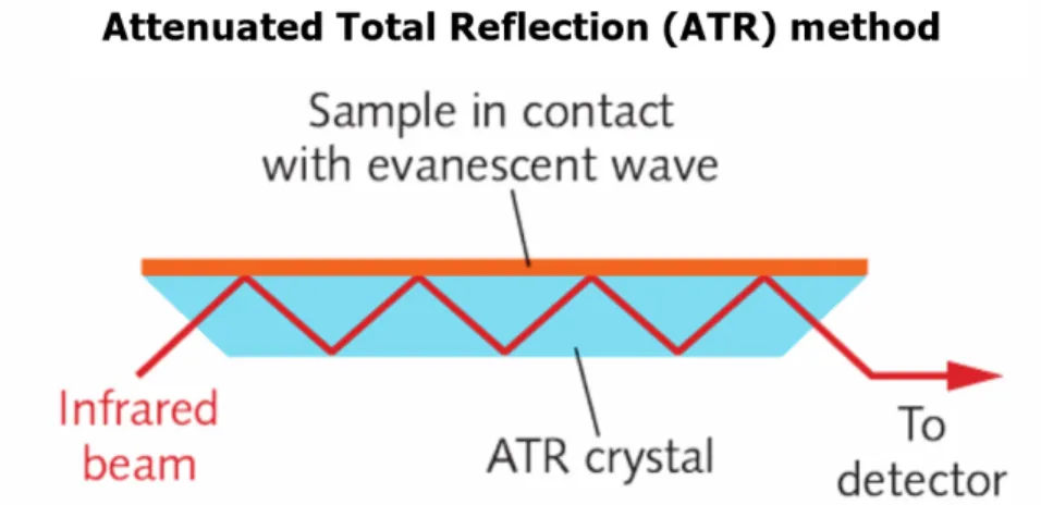
Figure 10: Illustration of the ATR FTIR method. Source: https://alliedscientificpro.com/ ... 23
Figure 11: Illustration of NIR-HSI hypercube of a scene. ... 25
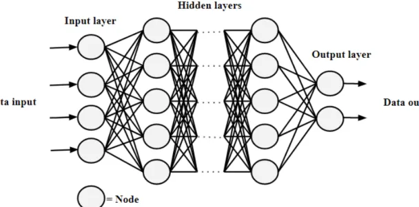
Figure 12: The Deep neural network processing structure. ... 28
Figure 13: A typical Trommel screen design. Source: https://www.alibaba.com/... 30
Figure 14: A typical vibrating screens design. Source: https://www.dynamiceq.com/ ... 30
Figure 15: A disc screen machine for the recycling of municipal waste. Source: https://www.adrecyclingmachines.com/en/ ... 31
Figure 16: Push-sorter. ... 32
Figure 17: Linear arm sorter. ... 32
Figure 18: Dropdown sorter... 32
Figure 19: One of the many variants of a magnetic separator. Modified from Fernando Pacheco-Torgal et al.,2019. ... 33
Figure 20: One of the many variants of Eddy current separator. Modified from Fernando Pacheco-Torgal et al.,2019. ... 34
Figure 21: A polymer density diagram. PVC and PET, highlighted in light blue, have very similar densities. Modified from Laurens Delva et al., 2019. ... 34
Figure 22: An illustration of a triboelectric separation method. Modified from Fernando Pacheco-Torgal et al.,2019. ... 36
Figure 23: a) Conveyor, b) light source (NIR), c) NIR-HSI camera, d) control unit for classification analysis, e) compressed air nozzles for multiple trajectories, f) a plastic piece with a normal trajectory towards the middle conveyor/bin and (g) multiple conveyors/bins for different plastics ... 38
Figure 24: Approach of work. ... 39
Figure 25: Mapping of the automated sorting system requirements. ... 46
Figure 26: The NIR spectrum of the four different plasticizers. Green: Castor oil, Pink: DINCH, Blue: DEHP and Red: DINP. ... 49
Figure 27: The NIR spectrum of sample X and sample 14, the Correlation Coefficient (CC) was 0.9984. ... 50
ix
Figure 29: The four not recognizable plastic flooring. ... 51
Figure 30: A flow chart representing the sorting and separation process in Concept 1. ... 52
Figure 31: A 2D illustration of Concept 1 from step A to F, i.e the size reduction and waste removal stage. ... 53
Figure 32: An illustration of the method of air separation, in this case, air suction is used to separate light fractions from heavy plastic floor pieces. Light fractions are sucked with air while the heavy fractions fall to the next conveyor. ... 54
Figure 33: A demonstration of the pattern recognition system (G) of concept 1. ... 54
Figure 34: A demonstration of the Near-infrared Hyperspectral imaging sorting system of concept 1. ... 56
Figure 35: A demonstration of the X-ray fluorescence sorting system of concept 1. ... 57
Figure 36: A flow chart representing the sorting and separation process in Concept 2. ... 58
Figure 37: Pattern scanning system. ... 59
Figure 38: Separation by X-ray fluorescence (XRF). ... 60
Figure 39: Separation by NIR. ... 60
Figure 40: Sorting by putting each type of plastic floor in its container (the push-slide is green). ... 61
Figure 41: A flow chart representing the sorting and separation process in Concept 3. ... 62
Figure 42: A CAD model illustrating the magnetic conveyor separation process. ... 63
Figure 43: A CAD model of the vibrating screen, conveyor belt, shredder, and waste containers. The vibrating screen doubles as the initial vibrating feeder. ... 63
Figure 44: A CAD model illustrating the air separation process in Concept 3. ... 64
Figure 45: A CAD model illustrating the first NIR-HSI separation process in Concept 3. ... 65
Figure 46: A CAD model illustrating the XRF separation process in Concept 3. ... 66
Figure 47: A CAD model illustrating the second NIR-HSI separation process in Concept 3. ... 67
Figure 48: A CAD-Assembly model of the complete sorting process in Concept 3. ... 68
Figure 49: A Flow chart diagram of the desired sorting process, conducted through interviews with Tarkett officials. ... 69
x
List of tables
Table 1: Recycling of defect plastic flooring. ... 2
Table 2: Recycling of torn plastic and installation spill. ... 4
Table 3: Muda, [7]. ... 11
Table 4: The three regions of the IR. ... 20
Table 5: The 16 physical floor samples sent to Holger for testing. ... 41
xi
Abbreviations
BTH Blekinge technical university
PVC Polyvinyl Chloride
TPU Thermoplastic polyurethane (TPU)
HE Heterogeneous
HO Homogeneous
HETF Heterogeneous Tarkett flooring HOTT Homogeneous Tarkett flooring LWM Low molecular weight Phthalates HWM High molecular weight Phthalates DEHP Di(2-ethylhexyl) Phthalate
DBP Dibutyl Phthalate
BBP Benzyl Butyl Phthalate DINP Diisononylphthalate DIDP Diisodecylphthalate DNOP Di-n-octyl Phthalate
DINCH 1,2-Cyclohexane dicarboxylic acid diisononyl ester TPS Toyota Production System
JIT Just-In-Time
NIR Near-infrared
MIR Mid-infrared
FIR Far-infrared
SWIR Shortwave infrared
MWIR Midwave infrared
LWIR Longwave infrared
NIRs Near-infrared spectroscopy MIRs Mid-infrared spectroscopy ATR Attenuated total reflection
FTIR Fourier Transform IR spectroscopy
HSI Hyperspectral imaging
NIR-HSI Near-infrared Hyperspectral imaging XRT X-ray transmission spectroscopy XRF X-ray fluorescence spectroscopy AI Artificial intelligence
NN Neural networks ML Machine learning DNN Deep neural networks ANN Artificial neural networks DL Deep Learning
1
1.Introduction
The thesis is a proposal from Tarkett, a flooring solutions company, globally recognized for a broad flooring offering in all major types of floor coverings and surface segments (excluding ceramics). Their offerings include heterogeneous and homogeneous vinyl, laminate, wood, carpet rolls and tiles, linoleum, artificial grass, and tracks. However, Tarkett AB in Ronneby manufactures and recycles homogeneous plastic floors only. These floors are used in hospitals, schools, sports facilities, elderly homes, and other public environments worldwide [1], [2].
Tarkett AB is currently looking to improve its recycling capabilities by adding a new source of recycling material. This new and additional source of the material consists of old used plastic floors. To accomplish this, Tarkett is considering a new production line for the recycling of this said source. This thesis will focus on the first step in the recycling line, the sorting system. A large portion of the current sorting system is conducted manually. There is no existing automatic sorting system that can identify and classify different types of plastic flooring.
There is a demand for an automation sorting system, for sorting mainly plastic flooring. The sorting system is expected to follow Lean production principles and working methods. It is also of interest to discuss safety aspects in the sorting system. The main task is to find existing technologies that can be further modified according to the organizational needs and properties of the material to be sorted. This dissertation will involve an illustration of a solution in how technologies are modified and implemented. Also, how the sorting system can be formed/structured to handle the incoming material.
1.1 Background
A new automated recycling line is planned to be built in the future. For this to be achieved, each sub-process in the line must be studied, for an increased understanding of the context of the entire recycling process. It is also important that the sorting of plastic flooring is automated first, as it is the first step in the line. More importantly, the focus will be on the sorting system. The sorting system needs to be adapted to the properties of the plastic floor as well as Tarkett's special needs for it to work in the best possible way.
Plastic floors
There are different variants of plastic flooring for different purposes. Plastic flooring has various ingredients that determine their properties, color, and appearance. Tarkett manufactures plastic flooring in different appearances and for different uses. There are homogeneous and heterogeneous plastic floors. Homogeneous plastic floors have the same pattern on both the front and back. The floor is considered suitable in, among other things, hospital and school corridors where lots of people and equipment pass daily, where the floor is subject to severe wear. While heterogeneous plastic floors do not have the same pattern on the front and back (in most cases). Heterogeneous plastic floors are constructed in several different layers, including the decorative layer, which consists of a printed sheet, and is available in many designs [3].
1.1.1 The current recycling line
The collection of torn plastic floors and installation spill at Tarkett Ronneby was introduced in 1996 with the aim of plastic floor recycling. Floor suppliers joined the system a few years later and now the entire flooring industry collects its waste via Tarkett in Ronneby under the name "GBR Floor
2 Recovery". Since 1999, the system for recycling waste installation has been taken over by the flooring industry. GBR takes care of the installation waste from large suppliers from all over Sweden. GBR commands the flooring companies, which install the floor, to collect all waste and send it to Tarkett Ronneby. Today, Tarkett Ronneby also receives installation spills from Tarkett products throughout the Nordic region [4], [5].
The recycling department is divided into two different departments. One department handles plastic flooring with effects that come from Tarkett's homogeneous plastic flooring factory. The other department handles torn plastic and installation spills. In the second department, there are different types of plastic flooring, homogeneous, and heterogeneous, as well as the competitors' plastic flooring. The different departments in the recycling process go through different processes due to their different processing needs and conditions (see Figures 1, 2, and 3). The various stages in the recycling department are, sorting of plastics flooring, granulation, sieving, washing, drying, removal of the plasticizers, and mixing (see Table 1 and 2).
Table 1: Recycling of defect plastic flooring.
Recycling of defect plastic flooring
Sorting of defect
plastic flooring The first step in recycling the plastic floor. The input source for this stage consists of faulty homogenous plastic floors and shredded spill from the production line at the same location i.e. Tarkett Ronneby. Plastic flooring that doesn’t meet the intended quality, coloring, and or consistency are sent to the recycling facility. They are rolled up to 2-meter-long cylinders (rolls) with an average weight of 200kg and wrapped in a thin transparent protective plastic film. The shredded plastic pieces arrive in metal containers while the rolled plastic flooring cylinders arrive vertically mounted and chained, both stored near the granulation machine. They are sorted into groups mainly depending on their content. Other sorting grapples are by color and family name.
Granulation The second step in recycling, where the plastic floor is granulated into small parts. The granulation machine (or rather a line) used for processing production waste and faulty plastic flooring is called A805 and consists of a manually operated lifting arm, two feeding mechanisms, conveying belt, and the granulation machine itself. Also, the granulation machine is capable of sieving the granulates from dust and other particles that may affect the reusability of the recycled material.
With the help of a manually controlled lifting arm, an operator lifts the vertically mounted plastic cylinders one at a time and places them horizontally on a lifting mechanism connected to a ramp. The plastic flooring rollers have to be oriented so that the exposed edge (the end) is facing the feeding mechanism. The lifting ramp is connected to a metal conveying belt, acting as a buffering zone for the first feeding mechanism. Before entering the buffering zone, the operator removes the transparent protective plastic film. This procedure is performed for each plastic cylinder until filling the buffering/loading zone. Then, the rollers are transported into the feeding mechanism via the buffered zone. The feeding mechanism is capable of detecting and grabbing the edge of the rolled plastic cylinders if placed correctly in the beginning. Furthermore, the feeding mechanism processes the rolled cylinder into smaller strips. The shredded production spills stored in metal containers inter the second feeding mechanism, the container is lifted and tilted until emptied. Both feeding mechanisms out the processed plastic flooring onto a conveying belt transporting the strips and spills to the granulating machine. The granulation machine
3 crushes plastic floors to smaller granules, and which are later stored in metal containers ready for mixing.
Mixing The mixing (Forberg mixer-A802) process is performed to neutralize and balance the coloring and material consistency of the recycled plastic. The mixture is performed per laboratory and production request. The recycling team receives an order for a new patch with clear instructions and measurements for color and flooring type. When the mixing process is complete, a sample is sent to the laboratory for testing and preparation. The mixing process itself is straight forward, the granulated homogeneous plastic flooring is mixed according to type, condition, and if possible, by color. However, the mixing of used and demolished homogenous plastic floors is performed at a very low scale due to impurities that will require intensive cleaning before mixing other sources.
Homogenous plastic flooring is the main ingredient and is mixed according to the type of filler and plasticizers present in the material. For example, homogenous plastic floors consisting of 40% plasticizers are granulated and stored separately from those with 60% plasticizers and or from those with different fillers. Furthermore, the metal containers storing the granulated plastic floors are manually transported to a docking station, one at time. At the docking station, a lifting mechanism empties the content off into a suction system feeding the mixer. The mixer utilizes six metal containers with a horizontal rotary mixing blade for additional mixing. These containers are connected to the mixer via a second suction/bump docking station. First, the mixer pumps and stores the granulated plastic into the six metal containers, equally distributed. Thereafter, the mixer sucks equally large portions from each of the six-metal containers and mixes them into one final patch stored in an ordinary metal container placed underneath the mixer.
Placed in a
metal container Finally, the various bonds are placed in metal containers, waiting to be used in the production of homogeneous plastic floors.
4
Table 2: Recycling of torn plastic and installation spill.
Recycling of torn plastic and installation spill
Sorting of all torn plastic and installation spill (part 1)
Spills that arise from the installation of plastic flooring, of which about 10% are flawless flooring, can be recycled. When collecting spills, they are placed in recyclable plastic bags (installation wastes from different suppliers are advised not to be mixed). The plastic bags must indicate who the current supplier of the plastic flooring is. When the bags are closed, they are placed in a special pallet container (different suppliers can be mixed). The bags are transported to Tarkett in Ronneby by truck. At Tarkett, the contents of the bags are sorted into a recycling facility. Each supplier is responsible for its installation spill and is sent to them as soon as the torn and spill flooring is identified [4], [5].
When the waste first arrives at Tarkett, they are placed in the recycling facility pending sorting. The bags may have to wait from a few hours to a few years depending on the sorting speed. Also, how many bags arrive and how much it is expected to recycle in the recycling department. It occurs that the plastic floors are placed outdoors when there is not enough room indoors, where they are affected by different types of weather. The sorting process starts with sorting Tarkett's homogeneous plastic flooring from other suppliers' plastic flooring. The sorting is done manually (by hand), where each bag is opened and emptied of the contents. Despite the clear rules about what the bags may contain, it often occurs that large variations of different plastic floors are placed in a bag from different suppliers as well as other materials such as knives, scalps, brushes, glue, paper tape, transparent tape, red tape, etc. Due to the large variety of materials and tools found in the bags, the sorting of the contents of the bags is very accurate, so that nothing is included in the recycling process except the plastic floors. When different suppliers' plastic floors are separated from Tarkett plastic floors, they are shipped to the respective manufacturer. When other materials and tools have been removed, the sorting plastic floors begin. Tarkett’s heterogeneous plastic flooring is placed in a metal container and later shipped to other Tarkett factory for heterogeneous plastic flooring. Unknown plastic floors that cannot be identified are placed in a GBR metal container and sent to energy combustion through incineration.
Sorting of homogeneous plastic flooring (part 2)
The different types of homogeneous plastic flooring are distinguished by appearance, by the same pattern on front and back and by the properties of the surface (from both front and back). All homogeneous plastic floors that are Tarkett's and don't have glue on them are mixed. Floors that cannot be mixed are Safe T and IQ-One. Flooring with glue cannot proceed in the recycling process, because there is not yet a flawless removal process of the glue, they are sent to the energy combustion. Other floorings that go to energy consumption are plastic flooring with polyester on the back as well as bad and old floors that can't be recycled. The foam that is collected from some plastic floors is recycled at Tarkett’s; it is mixed in their crush boxes until the amount is large enough to be recycled. The homogeneous plastic floors that have been identified are sent directly to the granulation process [6].
Granulation
5 glue, concrete, and spackle. Tarkett Ronneby recycles only homogenous plastic flooring. Moreover, homogenous plastic flooring free of impurities is sorted by present filler materials and granulated separately from impurities infected homogenous plastic flooring. The granulation is performed on a smaller granulation machine connected to a feeding conveyor belt operated manually. Currently, three workers manage the sorting, granulation, and logistics of the incoming plastic flooring waste. Two workers operate the granulation and ordering logistics and the third manages the inhouse logistics and transportation of container waste. Homogenous plastic floors with prohibited plasticizers, plastic floors of bad and unrecyclable conditions, polyester, and some floors with foam backing are shredded in a large granulation/shredding machine capable of processing wood and metal. The granulate is then sent to incineration for energy recovery.
Mixing
(part 2) The same process as in the defect plastic flooring recycling Placed in a metal
container (part 2)
The same process as in the defect plastic flooring recycling
6
Figure 3: Part 2: Recycling of torn plastic and installation spill.
1.2 Project goal
The purpose of this project is to conceptualize an automated sorting system for recycling plastic floors with existing technology and evaluation of mechanical solutions. Also, the conceptual sorting system should meet a list of requirements set by Tarkett. Tarkett can then use these concepts as the first step towards an automated sorting system for the recycling of plastic floors.
1.2.1 Research questions
To achieve the goals, three research questions were asked:
RQ1. How can plastic flooring be distinguished by manufacturers and from external contaminants using existing technology and how can these technologies be applied in an automated sorting line?
RQ2. How can Homogeneous plastic flooring be distinguished from Heterogeneous flooring using existing technology and how can these technologies be applied in automated sorting lines?
RQ3. How can Homogeneous plastic flooring be distinguished by type and surface contamination using existing technology and how can these technologies be applied in an automated sorting line?
1.5 Limitations of work
The current recycling line consists of several processes, but one of the very first and most important processes is the sorting and separation of plastic flooring and external waste. The sorting quality and capacity will affect and dictate the remaining processes of the recycling line. Thus, this thesis work will mainly focus on the conceptualization of a new automated sorting process and evaluation of current
7
technology that can be implemented for said process in a new automated recycling line. No additional sub-processes of the recycling line will be evaluated or analyzed other than the sorting process. The safety, implementation of Lean, costs, dimensions, and performance estimations of the proposed concepts will be vaguely discussed as it is very difficult to calculate and or predict these parameters without testing at an industrial scale.
Testing and experimentation have been limited due to the lack of available instrumentations, physical restrictions, and closing of public institutions imposed by the current pandemic COVID 19. Consequently, no self-made experiments or testing were conducted. Instead, limited collaborative testing was performed with selected companies.
8
2. Theory
Under this section, technologies and methods will be described for further use when conceptualizing solutions.
2.1 Lean production and safety
Under this heading section, lean production and safety will be presented, for further use. The information under this section is the basis for implementing Lean.
2.1.1 Lean production
Lean production was developed by the car company Toyota in Japan. It is a mindset based on business-based philosophy that is business-based on "human knowledge" and "human motivation". The founder is Taiichi Ohno, who founded "The Toyota Production System" (TPS) which is now known as Lean production. The purpose of Lean production is to identify and eliminate waste factors (also known as "Muda" in Japanese) in a production process that does not create value for the end customer. The idea is to create more value for less work. It is based on developing leaders, creating teams in a functioning culture in a constantly learning organization that can formulate a strategy and build relationships with suppliers. Fourteen principles are divided into four departments, which are followed in lean. They stand for: philosophy, process, employees and partners, problem-solving. These four sections are illustrated in a pyramid which can be seen in figure 4 [7].
Figure 4: The four departments for the Fourteen principles.
Principle 1: "Base management decisions on long-term thinking, even if it is at the expense of
short-term financial goals"
It is about aiming the organization towards a common goal and development, where philosophy lies with the basic principles of the organization. It is important to generate value for the customer, society, and the economy by increasing the value of the product and improving working methods within the organization.
9 Principle 2: "Create continuous process flows that bring the problems to the surface"
Create flow by linking different workflows to make it easy to move materials and information. People who can work together should be linked to create quick feedback and better control of processes. In this way, the problems that arise during production are clarified by the employees assisting with continuous improvements and development of the product in the various processes. The problems that arise should be solved immediately. The idea of creating a flow is also to remove unnecessary time that is spent when the work is at rest or moving.
Principle 3: "Let demand control to avoid overproduction"
By producing after the customer request, overproduction and inventory are reduced. In this way, a pulling system is created by the production based on the customer's request. That is the basic principle of just-in-time. Production should be regulated based on daily changes.
Principle 4: "Workload equalization (heijunka)"
The goals are to eliminate Muda (the eight types of waste), muri (people overload and equipment), and
mura (irregularities in the production process). Machines, equipment, and people should not be
overworked; therefore, the production schedule must be evened out. In other words, equalize the workload in all production processes.
Principle 5: "Build a culture where the process stops to solve problems so that the quality is right from
the start"
Support systems should be built so that problems can be addressed quickly. The support system must be able to detect problems, stop itself, and be able to alert personnel if a machine or process needs to be addressed. This system Jidoka, which is a combination of human intelligence and automation, is said to be the foundation of quality. Such a system requires the organization to strive for modern and quality-assured methods, to improve productivity in the long term.
Principle 6: "Use standardized work methods for continuous improvement and staff participation" It involves using stable and repetitive methods to maintain a predictable process, timing, and regular outflow. The organization should standardize the best working methods and gather knowledge about different processes to make the work more efficient. Participation should be allowed by creative and individual participation to improve the standard quality.
Principle 7: "Use visual control so that no problems remain hidden"
To help workers see if they are working according to a standard, simple and visible indicators can be created. Visual systems can be set up where the work is done to support the flow and the pulling system. It is said that visual control systems should be able to increase productivity, reduce errors, save time, facilitate communication, increase security, reduce costs, and give operators more control over the workplace.
10 Good technology should support people in the organization, not replace them. It's about eliminating waste by improving technology without threatening the stability, flexibility, and reliability of production. It is recommended to test new technology practically before it first enters a business process, manufacturing system, or products. New technology can be a threat to the flow because it is often unreliable and difficult to standardize. Clear advances must be seen in the new technology when it is evaluated so that it can be used in new work processes.
Principle 9: "Develop leaders who truly understand the work, live by the company's philosophy and
teach it to others"
This principle supports the development/training of leaders within the organization rather than hiring someone outside the company. The leader should be able to be the role model for the organization's philosophy and business model and teach it in the best way.
Principle 10: "Develop outstanding people and teams that follow the company's philosophy"
The purpose is to teach individuals and teams according to the company's philosophy. Teamwork must be taught for teams to work towards common goals. To improve the quality and productivity of the teams, several skills need to be put together into one team. This creates a stable flow where complex problems can be solved.
Principle 11: "Respect the expanded network of partners and suppliers by challenging them and helping
them improve"
To achieve set goals, the organization must support its partners and suppliers. The organization's parties and suppliers should be treated as an extension of the business. Appreciating them can help them grow and develop.
Principle 12: "Go and see with your own eyes to understand the situation (genchi genbutsu)"
To solve problems and improve processes, it is considered wiser to verify the information yourself. The sources of information should be examined based on personally verified information. This provides a deeper understanding of different data and situations.
Principle 13: "Make decisions slowly, and by consensus, carefully consider all options and execute
quickly"
Before the decision is made, all alternatives must be considered, when the choices are well made, they must be implemented quickly but cautiously. Nemawashi is a process that recommends that problems and potential solutions be discussed with all concerned to gather ideas.
Principle 14: "Become a Learning Organization by Reflecting Infinitely (hansei) and Constantly
Improving (kaizen)"
Stable working methods should be established that require minimal storage, this makes wasting easier to detect, as time and resources are visible to all concerned. Employees should be able to develop a process to achieve improvement (kaizen) and eliminate waste. Reflection (hansei) should be used at
11 reconciliation times after a project is completed. In this way, deficiencies are detected in the process and can be corrected so that the same mistake is not made again. The organization should be able to standardize its working method and not reinvent the wheel [7].
The TPS-House
To facilitate the understanding of TPS, a simple illustration was made by Fujio Cho (Taiichi Ohno's pupil) in the form of a "TPS-House". The house was shaped with a foundation, roof, and two pillars (see figure 5). In the roof the goal is written, which is to achieve the highest quality, lowest cost, shortest lead time, achieve the best safety, and have a high work ethic. The pillars contain just-in-time (JIT) and
jidoka, which means that an error must never pass to the next workstation/process. The building's
foundation consists of several blocks, which are equalization of production (heijunka), stabilization and standardization of working methods, and the Toyota way philosophy [7].
Figure 5: The TPS-House.
Muda (elimination of waste)
Eight major types of non-value-creating waste are mentioned (see Table 3). These main types of waste can affect different processes in an organization and not just production. Other processes that can also be affected are product development, order registration, and administration. Overproduction was the most serious waste because it caused most of the other waste [7].
Table 3: Muda, [7].
The eight main types of waste
1 Overproduction To produce without a request/order. It contributes to unnecessary inventory, personnel, and transport costs.
2 Waiting Waiting for something that is not available when needed, leading to large costs as well as delayed processes and downtime.
3 Unnecessary transport
12
4 Over-processing or
error processing Inefficient processes such as unnecessary work steps and poor tools that cause defects in production. It is considered a waste when the customer is provided with more value than he/she is willing to pay for.
5 Overstock It includes damaged goods, transportation and storage costs, excess raw materials, which can be caused by poor production planning.
6 Unnecessary work steps Any unnecessary movement that an employee must perform during their job such as reaching for tools. Stacking is also counted as waste. 7 Defects Includes the production of defective parts or improvement. Repair or
disposal, including inspection, leads to a waste of time and work. 8 Unutilized creativity of
employees By not allowing employees to have their voices heard, the business risks losing valuable and decisive ideas, improvements, and skills.
2.1.2 Safety and security
With the help of Lean, the workplace can be made safer. A safe work environment needs to be in order with work routines. With the help of 5S, a tool used in lean production, it may be possible to create a structured way of working in the workplace. The method 5S is in five steps, sort, set in order, shine, standardize and sustain ( English version) [8]. It is a method that describes how to achieve and maintain order in a systematic way in the workplace. The method leads to time savings, increased efficiency, and collaboration, as well as a safer work environment. According to lean, reliable, well-proven technology should support personnel and processes. The technology should support people in the workplace for increased safety. According to “Prevent” (which is an environmental knowledge distributor for companies), a stable work environment must be safe and contribute to good workers' health and organizational profitability. Different types of solutions can prevent accidents depending on the work environment that needs to be made safe. A safe working environment creates security for employees and visitors, also, promotes the organization in the long term [7], [9].
Methods for setting up a safe and secure work environment: -Emergency Stop
The purpose is to stop the machine immediately. It can be equipped with emergency brakes; it should not be used when the machine is switched off when workers have stopped working. A regular test must be performed to ensure that the emergency stop is working. It is highly appropriate that there is a clear sign showing the location of the emergency stop. The used color marking of the emergency stop is red with a yellow plate behind [9].
- Security stop
It stops machines if someone enters a hazard area, such as getting too close to a machine, tool, or opening. There are various types of safety stops, such as light rays that stop the machine if the light ray is cut. A contact mat as a mechanical stop, for example, through a contact strip when detecting touch. It should be made impossible to pass into the risk area. A regular test must be performed to ensure that the stop works [9].
- Breaks
Machines should be equipped with manual or automatic brakes (switched on when the machine is switched off), which can stop the machine completely under safe conditions. At a stop, accumulated
13 energy should be blocked or relieved. When locating machines with a long roll-out time, the brake must be activated by the actuator, the workers must not be put in the risk zone. On old machines may have pedals or buttons for braking, they should be marked. The function should be tested regularly to ensure that it works [9].
- Machine protection
The shielding must be constructed in such a way that it is not possible to access machinery risk areas. The purpose is also to protect against materials and tools with the risk of being tossed out. It shall prevent the opening of sealed openable covers and passages. This applies both when machines are in motion and stationery. Also, it should not work to start a machine if a passage is open [9].
There are three types of shielding:
● Fixed protection as an obstacle by example, access to rotating machine parts/shaft end in a lathe. This type of protection should be firmly fixed and can only be opened or removed with the help of a tool.
● A movable shield that protects against cutting tools and moving parts in machines. The sealed shielding’s should be able to stop the machine if it is opened or removed.
● Adjustable shielding is self-adjusting and prevents contact with the machine's various moving parts. These should be fixedly stable, easy to set, and can only be removed with tools [9].
2.2 Polyvinyl chloride (PVC)
Aside from PET and PP, Polyvinyl Chloride (PVC) and other chlorine containing-polymers are one of the most widely applied thermoplastic polymers in the world [10], [11]. PVC has been around for a long time, it was created in 1872 and commercialized in 1920, and unlike other heavily featured carbon-hydrogen polymers, PVC consists of around 57% Chlorine (by weight) as well as carbon and carbon-hydrogen
[12], [13]. Polyvinyl Chloride resin is derived from the polymerization of Vinyl Chloride Monomer molecules which is in turn made from the combination of chlorine (by electrolysis of saltwater) and ethylene (by extraction from crude oil) [14]. The repeating chemical structure of PVC is shown in figure 6.
Figure 6: The repeating unit of Polyvinyl Chloride (PVC).
PVC is produced as a white powder, the powder is then mixed with other ingredients to formulate different properties that are suitable for different products and needs [12]. Pure manufactured PVC without any additives is brittle and white-colored, moreover, PVC is usually manufactured into two variants; rigid and flexible. The rigid PVC and unplasticized (U-PVC) is durable and hard [15]. One of the main applications of rigid PVC can be seen in the construction industry as pipes, window profiles, sidings, floor, and roof coverings [10]. Other applications of rigid PVC can be seen in healthcare applications and as fiber threads for clothing [11]. Flexible or plasticized PVC (P-PVC) is achieved
14 with the addition of plasticizers to the main ingredient [10]–[12], [14], [15]. Flexibility is achieved through the interspersing of organic molecules (plasticizers) in between the PVC chains, thus, breaking the natural crystallinity of PVC chains [16]. Flexible PVC applications can also be found in the construction industry as indoor flooring, electrical insulation, and wires. Also, in medical and food products such as blood storage bags and food packaging [10], [14].
PVC has many preferable properties such as high flame and electrical conductivity resistance, high additive compatibility, and relatively small carbon-fingerprint, which makes it one of the most used thermoplastics today [10], [11]. However, this implies large amounts of waste and environmental pollution will be produced during and after its use. Energy recovery of polymers is still practiced on a large scale and widely considered as a prominent recycling method. Regardless, this presents a problem when considering the high chlorine content in PVC and the harmful HCl gases that can be released during incineration. It is therefore of economic and environmental interest to recycle PVC waste.
2.2.1 PVC Additives
Unlike other commodity polymers, PVC is not entirely made from oil, 57% of the molecular weight is derived from salt, thus, more effective usage of raw and nonrenewable materials. Moreover, the presence of chlorine creates strong polar regions which in turn enables a wider range of additive compatibility, thus making PVC the most modified polymer [16]. Also, the presence of chlorine gives the polymer increased flame-resistance properties [13], [14], [16]. PVC and polymer additives in general range from flame retardants to light and heat stabilizers, pigments, plasticizers, and fillers. Besides protecting and giving certain properties to the desired polymer, additives aid in the manufacturing process through lubrication and heat withstanding. Furthermore, some additives have multiple functions (multi-functional-additives), e.g. Carbon black can act as a coloring agent as well as Ultra Violet (UV) protection and electrical conductivity component [17].
Fillers
Fillers are optional additives and not necessary for the integrity of the chemical compound. Predominantly, fillers have been used to increase the bulk of the plastic while lowering material costs. Minerals like calcium are generally used as fillers in PVC due to the added bulk volume while keeping relatively low value (compared with PVC). However, nowadays fillers are used to offer positive attributes to the compound while still increasing the volume and lowering material costs. For example, fillers can be used for added strength and stiffness, improvement in processing and end of life, pigment replacement, heat, and light stabilizers. Primarily, fillers are inorganic minerals like calcium, talc, mica, silica, and Wollaston [17], [18]. However, there are organic alternatives like tree bark flour, nut flours, and rice husks. Modern plastics are often composed of fillers and can reach up to 70% of the plastic volume [18].
Plasticizers
Plasticizers are used to make the plastic flexible and soft for easier handling during manufacturing and application. Plasticizers consist of organic molecules that are somewhat polar therefore compatible with PVC. Plasticization is achieved when the interspersing of organic molecules (plasticizers) in between the PVC chains, thus, breaking the local crystallinity of PVC chains. The polar attraction between the plasticizers and polymer (PVC) binds them together, thus keeping the plasticized PVC matrix simple
[16]. Plasticizers have been used for many years, early examples include water for softening of clay and oil for waterproofing ancient boats made from the pitch. More than 30 000 different substances have been evaluated for their plasticizing properties only 50 of which are commercially available today.
15
Today, 1.35 million tons of plasticizers are consumed every year in Europe, out of which approximately 85% corresponds to flexible PVC applications. Furthermore, 25% of all consumed plasticizers in Europe (2017) corresponds to wire and cable applications while 20% to flooring and wall covering applications [19]. Ortho-phthalates (phthalates) are the most commonly used plasticizers today [14], [16], [19], they are organic molecules derived from alcohol and acid [20]. Furthermore, phthalates are divided into two groups; low and high molecular weight (LMW & HLM) [14], [19], [20]. Phthalates containing eight or fewer carbon atoms in their chemical backbone are classified as LMW. These are, DEHP, DBP, DIP, and BBP. Phthalates containing 7-13 carbon atoms in their chemical backbone are classified as HMW. These are, DINP, DIDP, DPHP, DIUP, and DTDP [14]. DEHP and DINP, DIDP and DPHP account for more than 75 % of all PVC plasticizers used in the world [21]. However, new and stronger phthalates regulations in both Europe and the US have limited the use of some LMW and HMW phthalates to specific amounts and applications due to health concerns, [14], [21]. Although, safer and commercially available alternatives to Ortho-phthalates exist. These include (to name a few), Terephthalates (DOTP), Cyclohexanooate di-esters (DINCH), Trimetallites (TOTM) and Citrates (ATBC) [20], [22].
Other additives
Other additives include heat and light stabilizers, coloring-pigments, anti-slip agents, electrically conductive fillers, and flame-retardant fillers. Flame retardants are very important fillers from a safety aspect against fire and smoke build-up. Moreover, the presence of the chlorine atom in the PVC chemical structure enhances the polymers' flame resistant [13], [14], [16]. However, when PVC eventually starts to burn, harmful HCl gases are released [16], [23]. Thus, flame-retardant fillers are used for additional flame resistance [23]. Moreover, flame retardants need to meet high performance and environmental requirements, thus the number of commercially available retardants is small [10]. The most commonly used flame retardants for PVC (to name a few) are Aluminum Trihydrate, Magnesium Hydroxide, Aluminum Hydroxide, and Antimony Oxide [13].
2.2.2 Calendared PVC Flooring
Modern calendared PVC flooring can be designed to imitate certain natural materials such as wood and minerals for more appealing offerings. Due to the positive properties of PVC and its cost-effectiveness when compared to other alternatives, it's used for domestic, commercial, and industrial applications. PVC flooring has seen extensive use in schools, hospitals, and other public and private gatherings due to its cleanability [24], durability [25], and maintainability [26]. Furthermore, the healthcare sector in Europe is dominated by PVC [27] due to its cost-effectiveness and shock absorbance capability. Also, PVC flooring doesn't attract bacterial growth and can easily be cut and repaired or replaced with hot plastic-welding [26].
Calendared PVC flooring (PVC carpet rolls) can be divided into two general types; Homogenous and Heterogenous PVC flooring. Homogeneous PVC flooring, usually one layered, offers more practical and economical use, although it can be less aesthetically appealing. Heterogeneous PVC flooring is constructed out of multiple layers, more color, and natural pattern options. The layers can even differ in material choice for more aesthetical and comfort options [25]. Furthermore, the average lifespan of PVC floors ranges from 10-17years [10], although depending on the use and maintenance, it can last even more [28].
16 The PVC content of plastic flooring can be as low as 20% [14]. The combined content of fillers, plasticizers, pigments, and other additives can outweigh the PVC content by six to one [13]. Typically, PVC flooring recipes consist of 28-50% PVC, 10-20% plasticizers, 25-60% fillers, and 0.5-5% other additives (pigments, stabilizers, and slip agents) [10].
2.2.3 PVC Recycling
PVC (polyvinyl chloride) is produced in large quantities due to its wide range of uses and varying uses in different industries. It is one of the most widely used polymers in the world as it has different uses and can be used in, flooring, furniture, packaging, power cables, different training applications, coated fabrics, etc. Because PVC has inherent durability properties, it is recyclable. Due to the low thermal conductivity, PVC products contribute to energy efficiency. PVC is energy efficient over several applications and has low thermal conductivity. It is also resource-efficient as it can be used to make new products.
Due to the versatility of PVC, it is possible to change the formulation parameters. This results in an improvement in the safety and eco-efficiency properties of the end product. It is very useful for enabling the recycling and production of new products. Due to the possibility of recycling PVC, production energy is economical.
The preservation of PVC quality and safety is of great importance because PVC is an important part of the individual's life because of its versatile properties that contribute to a better quality of life. PVC is considered to have a minimal environmental impact on carbon dioxide emissions compared to metal or glass products in the same application. Recovering PVC reduces emissions and can be recycled several times without significant loss of performance. It has been proven via laboratory tests on PVC pipes that PVC can be recycled up to eight times, depending on the application [29].
Phthalates
In plastic, phthalates are often used as plasticizers. In PVC, DEHP is used as a plasticizer, where it is primarily included in the manufacture of flooring, wallpaper, cable, foil, and weave plastic. Phthalates have also been used as plasticizers in paints, textiles, adhesives, etc. Because phthalate is not bound to the PVC polymer, it can be excreted throughout its lifetime. Some phthalates are classified as toxic; these are DEHP, DBP (dibutyl phthalate), and BBP (benzyl butyl phthalate). They cause reproductive capacity and birth defects, and DBP is environmentally hazardous and toxic, especially for aquatic organisms. Other phthalates classified as dangerous are “DEHP, DBP, BBP, Diisobutyl Phthalate and Di (branched C6-C8) alkyl phthalates and Di (branched and straight C7-C11) alkyl phthalates”. In Sweden, DINP, DIDP, and DNOP are less dangerous, and therefore the prohibition applies that they are not used for the manufacture of children objects such as toys and other things that can be put in the mouth. PVS recycling devices should comply with European requirements for REACH regulations for a safe environment and lifestyle [19], [30], [31].
PVC recycling methods Mechanical recovery
This method is suitably pre-subdivided and single waste stream waste from PVC. The mechanical recycling method is convenient when the waste is of a type of PVC product. The process may involve the mechanical grinding of waste products. If the product/substance is contaminated, which may depend on the type of waste material, it requires pre- or post-treatment. PVC thermoplastic properties make it
17 possible to heat, mold, or extrude PVC many times to create new products without loss of technical performance. There are two types of mechanical recycling, conventional and non-conventional technology.
Conventional technologies: The processes involving, sorting, shredding, and separating ingredients, which are then pulverized or granulated. The intention is that the granulate or powder should later be processed to create new products.
Non-conventional technology: This process uses solvent-based processes or pretreatment. This is to access PVC from difficult or intricate waste streams.
Raw material recovery
This type of recycling is best suited for unsorted plastic mixtures and waste streams containing composite material. The process may involve thermal treatments for the recovery of hydrogen chloride. Hydrogen chloride (HCl) can be reused at a later stage in PVS manufacturing or other types of manufacturing. Hydrocarbon, a combination of hydrogen and carbon monoxide, extracted from PVC products, can be used to produce syngas or as an ingredient in chemical production.
In this recycling process, different methods can be used: gasification, pyrolysis, and dehydrochlorination.
1. Gasification
This step in the process is based on a high-temperature reaction using a limited amount of air, oxygen, or steam. The process can convert PVC waste into carbon dioxide and be singed, which can be used in the production of chemical raw materials such as methanol, ammonia, oxo-aldehydes, or the production of fuel.
2. Pyrolysis
This step in the process is used to convert non-halogenated plastics and involves temperature degradation, mainly without air or oxygen. It should provide a residual carbon (still considered a challenge) or heavy hydrocarbons. Due to chlorine-containing plastics, this becomes a special challenge.
3. Dehydrochlorination
This step contains more gentle degradation processes involving the removal of chlorine and gasification or pyrolysis. For this to be possible, the process takes place under pressure in water in ionic high boiling liquids, and can also be carried out in a dry processor, such as through melting, or hydrogenation [29].
2.3 Spectroscopy
The study of how light, electromagnetic radiation, interacts with matter is called spectroscopy [32]. Although, the general term used today for the science behind the interaction of energy and matter is called spectroscopy. However, as aforementioned, electromagnetic radiation is the most widely used spectrometric method for spectroscopic analysis [33]. Electromagnetic radiation encompasses a variety
18 of radiation, hence there are various types of spectroscopy (e.g., x-ray, ultraviolet light, visible light, and infrared spectroscopy) [32]–[34].
Spectroscopy is used (among other things) in analytical-chemistry and material analysis for the qualitative and quantitative determination of molecules [32], [33]. When performing analytical spectroscopy, electromagnetic radiation of different frequencies (X-Ray, UV, IR, etc.) is applied to materials. Then, spectral characteristics of the material are obtained by recording the interaction (i.e. absorption, emission, reflection, etc.) between the electromagnetic radiation and materials. Furthermore, the material spectra (spectral characteristics) is typically a graphical representation of the intensity (reflection, emission, and or absorption) versus the frequency (often converted to wavelengths in Nanometers). All materials differ from one another in their molecular structure and constituents; thus, each material interacts differently with different electromagnetic energies. Also, by comparing the obtained material spectra, differences can be found between a set of materials [32]–[34].
2.3.1 Infrared (IR) Spectroscopy for polymer identification
IR spectroscopy can be used as rapid, nondestructive, quantitative, and qualitative analysis of polymers. IR-spectroscopy is widely used in polymer science and by physicists and chemists for quality and classification analysis of a wide set of materials [34].
The physical foundation of IR spectroscopy is based on the interaction of electromagnetic radiation within the IR-region (ranging from 700 nm to 1000 000 nm in wavelength and from 14 000 𝑐𝑚−1 to 10
𝑐𝑚−1 in wavenumber) with mass. Wavenumber (𝑐𝑚−1) denoted by 𝜈is often used instead of
wavelength, it represents the number of waves per centimeter and is given by 107/𝜆𝑛𝑚[10], [34], [35].
Polymers are composed of small repeating molecules (repeating units) linked together in long chains and the repeating molecules are composed of atoms bonds. The bonds between the atoms and molecules are not static but in motion (or rather in vibration). Under ambient temperature, the molecules and atoms vibrate within their fundamental energy levels (vibrational states). The participating atoms (or group of atoms) in chemical bonds are being displaced with relation to their displacement to one another in a defined frequency depending on the strength of the chemical bonds and the mass of the atoms (or group of atoms). Furthermore, when external energy is transferred to the molecules via IR radiation of a given wavenumber (𝑣) and absorbed by the atoms in the molecules, the amplitude of these vibrations will increase due to the transitioning of electrons to different energy states. If the initial energy state is denoted by E1 and the final state denoted by E2, then the IR-radiation of the given wavenumber (𝑣) is absorbed only when equation 1 (provided by Planck’s Equation) is upheld. Where h is Planck’s constant and c velocity of light.
𝑣 =(E1-E2)/hc (1)
Similarly, equation 1 defines the wavenumber (or frequency) of the emitted radiation of the reverse transition from higher to lower energy state after the atoms or rather the excited electrons return to their initial state. The vibration of the chemically bonded atoms coexisting in a molecule is referred to as bond deformations such as (to name a few) stretching, bending, wagging, and twisting. The simpler and more representable types are bond stretching and bond bending [34], [36]. The bond stretching can be of symmetrical or asymmetrical movement, see figure 7.
19
Figure 7: Illustration of the most common bond deformation (vibration). Modified from Manas Chande, 2018.
Different molecules (atom bonds) absorb IR-radiation at different frequencies (wavenumbers) and correspond to different bond vibrations (or bond deformations). Thus, a spectrum of the absorption of IR-radiation over a range of frequencies (or wavenumbers) can be obtained. Additionally, the presence of other atoms in the molecule does not heavily affect the characteristics of the specific bonds. Thereby, the wavenumber corresponding to particular bond deformations due to absorption is approximately the same for all molecules (including polymers) for that specific bond [34].
Obtaining the IR spectra of polymers may appear difficult due to the large chains of molecules. Conversely, it is relatively simple, polymers consist of repeatable units containing vibrational groups of the carbon backbone like C-C, CH, CH2, CH3, C-O, CN, C-CL, etc. [36]. Since different materials are made up of different and unique combinations of atoms, no two materials are exactly alike. Thus, different materials produce different IR spectrums, therefore, identification of organic materials (including polymers) is achievable. Although, the identification between hydrocarbon polymers (hydrocarbon materials in general) can present some problems due to similarities in the material constituents. However, polymers containing various special elements such as O, CL, N, S, C creating functional groups (such as C-CL, C-N, C=O, etc.) can be analyzed with relative ease [10], see figure 8.
Figure 8: Comparison between PET and PVC, important vibration bonds are shown corresponding to specific wavenumbers. Modified from Melissa R. Jung et al., 2017
20
Near and Mid Infrared Spectroscopy
The IR range can be divided into three regions; near-infrared (NIR), mid-infrared (MIR), and the far-infrared region (FIR), see table 4. Therefore, IR-spectroscopy is also divided into three corresponding regions.
Table 4: The three regions of the IR.
Range In Wavelength (nm) In Wavenumbers (𝑐𝑚−1)
NIR 780 to 2500 14000 to 4000
MIR 2500 to 25000 4000 to 400
FIR 25000 to 1000 000 400 to 10
However, the interesting regions for polymer and other organic additives identification are performed in the NIR and MIR regions [35]. Starting with the NIR-region first, the theory behind near-infrared spectroscopy is the same for all IR-spectroscopy. That is, radiation of a given frequency that can supply the exact amount of energy needed for a molecule (or bonds of atoms) to transition between two vibrational levels can be absorbed and thus, produce vibrational excitation specific to that bond and energy. This means, for a given range of wavenumbers, some frequencies, those that match the energy difference (equation 1) of two vibrational states, can be absorbed by the molecules. Conversely, frequencies of wavenumbers that do not correspond to any energy differences will not be absorbed, while some are partially absorbed. Thus, by measuring the intensity of absorption versus the corresponding wavenumber and making a graphical representation (spectra), a material or substance can be determined [37].
The transition of the vibrational state from a ground state (n=0) to a final state (n=1) is called the fundamental vibration, see figure 9. The wavenumbers corresponding to the frequencies triggering the fundamental vibrations coincide mainly in the MIR (and bit in the FIR region), more precisely in the 4000 to 200 𝑐𝑚−1 region. Fundamental vibrations can’t be reproduced within the NIR region. However,
the overtones of the fundamental vibrations and combination bands of two or more fundamental vibrations can be obtained in the NIR region [35].
![Table 3: Muda, [7].](https://thumb-eu.123doks.com/thumbv2/5dokorg/4267474.94576/22.893.100.756.934.1137/table-muda.webp)