School of Innovation Design and Engineering
V¨
aster˚
as, Sweden
Thesis for the Degree of Master of Science (120 credits) in Computer
Science with Specialization in Software Engineering — 30.0 hp —
DVA501
MAPPING UML DIAGRAMS TO THE
REACTIVE OBJECT LANGUAGE
(REBECA)
Vladimir Djukanovic
vdc16001@student.mdh.se
Examiner: Marjan Sirjani
M¨
alardalen University, V¨
aster˚
as, Sweden
Supervisor: Antonio Cicchetti
M¨
alardalen University, V¨
aster˚
as, Sweden
Abstract
Unified Modeling Language (UML) is a de-facto standard modeling language with an extensive syntax and notations that can be used to model systems of any kind. How-ever, being a general-purpose language, its semantics are intrinsically under-specified and broad to leave a room for different interpretations. This, in general, hinders the ability to perform formal verification of models produced with a specific domain in mind. In these cases, it is usually more suitable to map the UML models to other do-mains, where modeling concepts have stricter semantics. Notably, Reactive Objects Language (Rebeca) is an actor-based language with a formal foundation and formal verification support. This paper aims to identify a subset of UML modeling concepts compatible with the domain of reactive and distributed systems as modeled in Rebeca. In this respect, this work proposes a conceptual mapping between a sub-portion of UML and Rebeca, with the goal of enabling formal verification early in the design process. In particular, we investigate Rebeca syntax, and for each Rebeca concept, we provide the corresponding concept in the UML, as part of an iterative process. This process ends when all Rebeca concepts are exhausted and comprehensive mapping procedure emerges. Additionally, validation is an important part of this paper as it aims to establish confidence in the developed mapping procedure (in post-conversion validation) and avoid doing the transformation if the design is not compatible with the mapping procedure (in pre-conversion validation). As part of the pre-conversion validation, in order to establish the compatibility with the mapping procedure, we provide an extensive list of correctness attributes. As part of the post-conversion validation, the mapping procedure is validated by transformation on the provided ex-amples. The results of this transformation show the wide range applicability of the mapping procedure and serve as an assertion of its comprehensiveness.
Table of Contents
List of Figures 4
List of Tables 5
Glossary 6
1 Introduction 7
1.1 Goal and Problem Statement . . . 8
1.2 Thesis Outline . . . 9
2 Background 9 2.1 Unified Modeling Language (UML) . . . 11
2.2 UML Diagrams . . . 12
2.2.1 Structural Diagrams . . . 13
2.2.2 Behavioral Diagrams . . . 15
2.3 Reactive Objects Language (Rebeca) . . . 17
2.3.1 Rebeca - Actor-based Modeling . . . 18
2.3.2 Rebeca Syntax and Semantics . . . 18
3 Related Work 21 4 Research Process 23 5 A Mapping Procedure for Transformation of UML Models to Re-beca Models 26 5.1 Requirements Analysis . . . 26
5.2 Identification of Rebeca Concepts . . . 27
5.2.1 Extraction and Analysis of Rebeca Concepts . . . 27
5.3 Identification of Corresponding UML Concepts - Iterative Mapping . 30 5.3.1 Structural UML Concepts . . . 31
5.3.2 Behavioral UML Concepts . . . 36
5.4 Detailed Mapping Procedure Description and Overview . . . 47
6 Method Evaluation 54 6.1 Pre-Conversion Validation . . . 54
6.2 Post-Conversion Validation . . . 58
6.2.1 Practical Example - Validated Source Models . . . 59
6.2.2 Manual Transformation - Acquiring Target Models . . . 62
6.2.3 Capturing Rich Behavioral Concepts - Example . . . 67
6.2.4 Results, Applicability and Potential Improvements of Map-ping Procedure . . . 73
7 Discussion and Limitations 78
List of Figures
2.1 Class diagram example . . . 14
2.2 Object diagram example . . . 15
2.3 Sequence diagram example . . . 16
2.4 State-machine diagram example . . . 17
2.5 Rebeca syntax [1] . . . 20
4.1 Research process cycle . . . 24
4.2 Mapping procedure - iterative creation process . . . 24
4.3 Validation process . . . 25
5.1 Combined Fragment of type ALT . . . 38
5.2 Combined Fragment of type ALT - with logical operator . . . 38
5.3 Combined Fragment of type ALT - with conditional comparison . . . 39
5.4 Initiating message call . . . 40
5.5 Asynchronous message call to another class . . . 40
5.6 Asynchronous message call to self . . . 41
5.7 Combined Fragment of type LOOP - excluding range . . . 42
5.8 Combined Fragment of type LOOP with the inclusion of range . . . . 43
5.9 Combined Fragment of type LOOP with the inclusion of range and iteration variable . . . 43
5.10 Setter global method call . . . 44
5.11 Regular inline set . . . 45
5.12 Array position inline set . . . 45
5.13 Inline set by overriding default assignment operator . . . 46
5.14 Regular local variable declaration . . . 47
5.15 Regular local variable declaration with initialization . . . 47
5.16 Local array declaration . . . 47
6.1 Class diagram - structural source . . . 59
6.2 Object diagram - structural source . . . 59
6.3 Sequence diagram - Train constructor - behavioral source . . . 60
6.4 Sequence diagram - Train youMayPass method - behavioral source . . 60
6.5 Sequence diagram - Train passed method - behavioral source . . . 60
6.6 Sequence diagram - Train reachBridge method - behavioral source . . 61
6.7 Sequence diagram - BridgeController leave method - behavioral source 61 6.8 Sequence diagram - BridgeController arrive method - behavioral source 62 6.9 Class diagram - Node class - structure . . . 68
6.10 Object diagram - Node instances - structure . . . 68
6.11 Sequence diagram - Node constructor - behavior . . . 68
6.12 Sequence diagram - Start global transaction method - behavior . . . . 69
6.13 Sequence diagram - Cooperator response method - behavior . . . 70
List of Tables
5.1 Comprehensive mapping procedure - textual representation . . . 49 5.2 Comprehensive mapping procedure - detailed conceptual representation 51 5.3 Comprehensive mapping procedure - Rebeca-centric concepts . . . 52 6.1 Pre-conversion validation correctness rules . . . 57
Glossary
UML Unified Modeling Language
MDE Model-Driven Engineering
OCL Object Constraint Language
Rebeca Reactive Objects Language
rebecs Reactive Objects
RMC Rebeca Model Checker
MOF Meta-Object Facility
OMG Object Management Group
AMN Abstract Machine Notation
OOP Object-Oriented Programming
1
Introduction
The exponential growth of software complexity with a notable focus on safety-critical applications [2] introduced the demand for a new approach to development. As a positive reaction to this, the UML was created, that now represents the standard-ized notation for modeling and documenting software systems [3]. UML initiated the creation of a new approach to design, called Model-Driven Engineering (MDE) that focuses on the use of models as the main building blocks of the system [4]. The most anticipated area of MDE is model transformation which, in its subset, enables a code to be automatically generated from models [4]. Hence, the model transformation facilitates a transition of the models towards other domains.
Despite its general use and acceptance as a de-facto standard modeling language, the UML has a serious drawback [5]. This comes from the fact its semantics are intrinsically under-specified and broad to leave a room for different interpretations. Hence, multiple and potentially contradictory interpretations of one and the same model are not excluded, and automatic interpretation must be hard-coded in some way [6]. This, in general, hinders the ability to perform formal verification of models produced with a specific domain in mind. This gap in the UML creates a demand, for formal verification to establish the correctness of the models early in the process. In these cases, it is usually more suitable to map the UML models to other domains, where modeling concepts have stricter semantics.
That is where Rebeca comes into the picture. Rebeca is an actor-based language with a formal foundation. Rebeca is an easy to use JAVA alike language and a modeling language, with formal semantics and formal verification support [1]. To address the shortcomings of UML, it would be interesting to provide a detailed conceptual mapping between a sub-portion of UML and Rebeca. In other words, we want to identify a subset of UML modeling concepts compatible with the domain of reactive and distributed systems as modeled in Rebeca. This should ultimately lead to implementation of the model transformation for such mapping.
We also want to have an appropriate validation phase with different reasons: First, after the creation of the mapping procedure, the necessity for its validation on applicability scenarios is obvious. This could be performed differently depend-ing on different factors includdepend-ing research limitations (i.e. time). In an optimistic scenario, we would like to provide a model transformation tool, in which case the automated tool would be running the transformation and afterward validation on different applicability scenarios with the purpose to establish the correctness of the target models (runnable in Rebeca and reflecting the source UML models). In a more realistic scenario, the validation could be performed in cooperation with ex-ternal subjects where they would do the transformation from source UML models to the target Rebeca models by manual transformation, using the mapping procedure. Second, by enabling a validation of the source UML models we want to avoid per-forming the transformation if the design is not compatible with the mapping proce-dure or in other words is outside the domain. In fact, in that case, the costs of fixing design defects would be far more relevant than anticipating problems in obtained Rebeca models.
1.1
Goal and Problem Statement
The past decades have witnessed significant efforts towards simplifying a process of developing a system, reducing system complexity and conducting a formal ver-ification of the developed system. The creation of the UML and its confirmation as a de-facto standard modeling language answered on the first problem, to some extent [3]. Moreover, it shows a serious potential to reduce the complexity of the developed system and therefore provide more easily maintainable software products. However, UML has a serious shortcoming as it lacks complete formal semantics and this hinders the ability to perform formal verification of models produced with a specific domain in mind. On the other side, Rebeca language has formal semantics and provides support for formal verification that enables more accurate evaluations to be performed [5]. In this respect, it would be beneficial to establish a conceptual mapping between a sub-portion of UML and Rebeca with the goal of enabling for-mal verification early in the design process.
The main objective of this thesis is to investigate the viable ways of mapping UML models towards Rebeca models. The mapping should be detailed enough while fo-cusing on the minimalist diagrammatic approach in terms of what is the minimum UML information (including both the set of diagrams and information contained in the diagrams) that is needed for target Rebeca concepts. Following the aforemen-tioned, it is logical and expected that there exists a need for the behavioral diagrams to obtain meaningful information in Rebeca to be analyzed and verified by a formal verification tool. Moreover, there could be a need for structural diagrams, in order to model the structure before introducing behavior, and we consider them as well for the mapping. The overall objective of the thesis is to conduct an analysis to identify the minimum UML diagrams that will be used as sources for formal verifi-cation in Rebeca. Additionally, we want to provide a detailed mapping procedure to translate identified UML concepts towards fitting Rebeca concepts with considera-tion of important factors as available resources for conducting the thesis. Hence, we strive to provide an achievable detailed enough mapping procedure that is in accor-dance with the scope of this research. The mapping procedure should be detailed enough to enable the implementation of a model transformation tool. The model transformation tool shall perform the automatic translation of the UML models to Rebeca models within the established applicability scope of the mapping procedure. In the end, the thesis aims to provide a proper validation of the proposed mapping procedure in order to show the applicability on different scenarios.
The identified problems can be written in the form of research questions as follows:
1. RQ1: What are the minimum UML diagrams required to serve as sources for target Rebeca concepts in order to obtain something meaningful to be analyzed through Rebeca?
2. RQ2: What is the adequate mapping procedure between the identified UML concepts and Rebeca concepts?
3. RQ3: What is the applicability of the proposed mapping procedure and its proper substantiation?
1.2
Thesis Outline
In Section 2, we explain what are the main development and life-cycle issues with evolving software solutions. Directly related to this, we explain various concepts among which is UML that is attempting to address this issue. However, due to its shortcomings, it is required to go even further into the subject by introducing Rebeca language and discussing how we can reap the benefits of a mapping between Rebeca and UML, for modeling the domain of reactive and distributed systems. This leads us to the main objectives of this research by conclusively proposing the mapping procedure and the validation process. In Section 3, we discuss related work and the contribution that this research is attempting to achieve. In Section 4, we are reasoning about a research methodology that is used in this thesis, and we propose our research goals. In Section 5 we are going deeper into the subject by executing the proposed iterative process until we reach a satisfactory level of comprehensive-ness of the emerged mapping procedure. Initially, this includes a specification of all the Rebeca concepts. Then, for each of them, we attempt to provide minimum information in the UML that is necessary for an adequate mapping to be accom-plished between the two. Indeed, if any limitations are found we document these in a separate subsection and we attempt to reason about them and provide a method for addressing each of them. In section 6, we describe the emerged mapping procedure on two examples constructed of the UML models and corresponding Rebeca models that are produced by transformation, based on the proposed mapping procedure. Initially, before the translation to Rebeca is performed, we provide an extensive list of correctness attributes as part of the pre-conversion validation, to avoid performing the transformation and reaching faulty Rebeca models if the design is not compat-ible with the mapping procedure. After the transformation on pre-validated UML models is done, we proceed by presenting the results of our research and evaluat-ing this process regardevaluat-ing applicability. This indeed represents the post-conversion validation phase, in particular, reasoning about the applicability of the mapping procedure with the inclusion of the limitation analysis. Finally, in Section 8, we conclude the work with a brief summary and possible future research directions.
2
Background
The common traditional techniques for software development including in its core significant programming efforts are failing to meet the newly introduced demands on the software market [3]. This situation, that caught everyone off guard, was caused by the uncontrolled expansion of software throughout all domains including safety-critical domain in which the consequences of failure could be catastrophic. The software is becoming widespread and complex [2]. This implies it is harder to build and maintain the software that causes an increase in the time and costs of these activities. This also leads to lower quality of software and inability to properly establish its correctness [2].
It is clear that there exists a need for simplifying the development process as well as reducing the time and cost for development and maintenance of software while
improving its reliability (continuity of correct service).
As an attempt to give an answer to these questions, different concepts, method-ologies, and processes have been proposed during the past decade corresponding to different sides of the problem.
These solutions include methodologies for simplifying development and maintenance processes, reducing software complexity and providing new verification techniques such as model checking, theorem proving, etc. as means of formal verification with the inclusion of their automation.
On one side, we have a UML that is focused on reducing software complexity and programming efforts. UML represents the standardized notation for modeling and documenting software systems. UML initiated the creation of a new approach to the development process, called MDE [4]. We will explore a model transformation that is one of the most important concepts in MDE, that we want to use for transforming the UML models towards other domains.
On the other side, the formal verification techniques that were introduced are fo-cused on proving that a software conforms to a formal specification for its intended behavior. Model checking is one of the most important formal verification tech-niques. It exhaustively and automatically checks whether the observed model meets its given specification. However, it is important to stress that not all languages are supported by a model checker in which case it is necessary to perform a transfor-mation to another language that is supported by a model checker.
Also, it depends on what kind of systems are we verifying. Currently, we are ex-periencing a shift towards parallel systems that enable concurrent execution of the programs. This change is mainly due to physical limitations of processing units, that emerged, and caused a shift towards multicore processors (single integrated circuit consisting of multiple core processing units capable of concurrently execut-ing different tasks) [7]. As it wasn’t possible to keep up with making single core processors any faster, multicore processors were introduced in hope that they will result in increased processing speed.
However, these processors require software solutions to be accommodated for paral-lel execution. In other words, if we want to take advantage of the hardware we have available, we need a way to run our code concurrently.
One of the first approaches for parallel execution was established with the use of Threads [8]. However, Threads proved to be extremely complex and volatile that made them impossible to control, with additional danger of deadlock occurrences (a condition in which each member of a group is waiting for another member, including itself, to perform an action, i.e. sending a message or more commonly releasing a lock) [8].
A counter-approach [8] that solves the shortcomings of Threads is actor-based mod-eling.
The actor model is a conceptual model to deal with concurrent computation. It defines some general rules for how the system’s components should behave and in-teract with each other [9]. We will discuss in detail about actor-based modeling and its constructing elements in Section 2.3.1.
that is created in an effort to bridge the gap between formal verification approaches and real applications [1].
Regarding the objectives of this thesis and how it relates to all this, by identifying a subset of UML compatible with the domain of reactive and distributed systems as modeled in Rebeca, we strive to enable formal verification early in the design process.
In the following sections, we will provide a detailed definition of UML and Rebeca and all concepts related to them that will be covered in this thesis.
2.1
Unified Modeling Language (UML)
UML represents a standardized notation for modeling and documenting software sys-tems. UML is under constant evolution by the Object Management Group (OMG) group [3]. Moreover, UML has become a general-purpose language, that means any system can be modeled by using its concepts. The use of UML ultimately leads towards reduction of the complexity of both the development process and the developed system. Besides, having one standard language for modeling has many advantages to software development, such as simplified training and unified commu-nication between development teams [5].
Furthermore, UML initiated the creation of a new approach to the development process, called MDE [4]. MDE is a software engineering branch that advocates the use of models as the main building blocks of the system. Models represent high-level abstractions of the observed real phenomena which focuses on the main segments while hiding the unnecessary information from the modeler of the system. This con-tributes to the reduction of the complexity of both the development process and the developed system. UML diagrams are used for a visual representation of the system based on different aspects and views, in order to provide a better understanding, maintenance, alterations, and documentation of the system.
The most anticipated area of MDE is model transformation [4] which, in its sub-set, includes automatic code generation from input models and aim to reduce the programming efforts and therefore human-error that is part of the programming process.
Despite its general use and acceptance as a de-facto standard modeling language, the UML has some serious drawbacks [5]. It is complex and tools can support only a part of its entire capability. Moreover, the expectation that training will become easier with UML being a standard, unified language, did not produce expected results and was characterized as over-promised. Also, UML still lacks complete formal semantics even though many achievements have been made through extensive research towards a common goal to define semi-formal semantics (with Object Constraint Language (OCL)) as well as attempts towards formalizing UML semantics [5,10–13].
This has a negative effect on the UML and the many expectations related to it. These effects and risks associated with the use of UML are amplified if we take into consideration safety-critical domain in which a failure could have catastrophic consequences and therefore these systems cannot be left unverified under any cir-cumstances. Furthermore, in such cases where the criticality of the systems is ac-centuated, it is required to model systems in formal languages to be able to use
formal verification techniques, early in the development process.
One of the advantages of UML that helps us deal with these drawbacks is the possi-bility for UML customization that is established by definition of UML profiles [14,15]. A profile is a subset of UML syntax with the inclusion of a set of well-defined rules. The provision of these rules add standard (known) UML elements to the subset and define some additional semantics in a natural language that ultimately leads to the creation of a hybrid UML language accommodated with the semantics of the target language [5,14,15]. However, UML profiles are significantly limiting the true potential of UML by creating a domain-specific UML language that is a hybrid be-tween the source UML and other domain-specific languages used as a target. This approach restricts the use of the new hybrid UML to only that domain (language). With respect to this paper, we strive to keep the UML in its native form without introducing a UML profile in order to avoid producing a restricted hybrid UML language. Naturally, we need to set some rules that will be used as correctness at-tributes for validating source UML models before conversion to Rebeca takes place and establishing that the models are indeed in the Rebeca domain. These correct-ness attributes essentially gives us an early answer about the compatibility of source UML models with the mapping procedure.
2.2
UML Diagrams
UML is based on diagrammatic reasoning. It can be described with the proverb: a picture is worth a thousand words. Models represent high-level abstractions of the observed real phenomena which focuses on the main segments while hiding the unnecessary information from the modeler of the system. UML diagrams are used for a visual representation of the system based on different aspects and views that define the information that is modeled within them [15,16].
By using visual representations, we are able to better understand possible flaws in the software early in the process and provide easier development, modification and documentation processes. UML diagrams can be defined as blueprints of software, where each type of diagram is used for modeling a certain aspect of the software whether it is its structure or behavior.
UML is not a stand-alone programming language like Java, C#, etc.. However, with the use of certain automation tools for model transformations, it can be used as a pseudo-programming language [16]. In such case, the whole system needs to be modeled with the use of various UML diagrams and can be directly translated to code with the use of specialized tools for automating model transformation between UML and the desired programming language.
The broadest two categories of UML diagrams which encompass all other categories are:
1. Structural Diagrams (Section 2.2.1)
2.2.1 Structural Diagrams
Structural UML diagrams analyze and depict the structure of the software or process. We provide the list of available structural diagrams:
1. Class Diagram
2. Object Diagram
3. Component Diagram
4. Composite Structure Diagram
5. Deployment Diagram
6. Package Diagram
7. Profile Diagram
We will only elaborate on those diagrams that are of interest for this thesis. These diagrams are the ones that are most commonly used to represent the struc-ture of the software and provide input information for model transformation. These diagrams include Class Diagram and Object Diagram.
Class Diagram is the most common structural diagram for designing or doc-umenting software. Considering the current trend and common use of Object-Oriented Programming (OOP) paradigm that covers this thesis as well, using this type of UML structural diagram is completely reasonable solution [16]. It is accom-modated with the main building blocks used in OOP such as Classes that consist of Attributes also known as data fields, and functions also known as behaviors.
Figure 2.1: Class diagram example
As can be seen in Figure 2.1, a basic example of the class diagram is provided. We notice that both classes: Checkings Account and Saving Account are generaliza-tions (represented by a blank headed arrow) of the class Account, that means they are the children, in the inheritance tree, of the class Account. This represents the same type of inheritance as in any OOP language. Besides, the diagram is quite self-explanatory and it clearly states the consisting classes and how they are inter-related between each other.
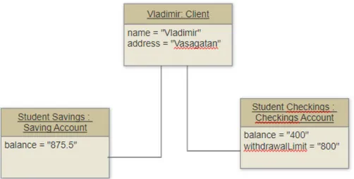
Object Diagram is another type of structural diagram that we are going to consider in this thesis. In order to define this type, we need to look at OOP paradigm once again. We know that classes are used as blueprints upon which objects are built by use of instantiation mechanism. A class can have objects instantiated from other classes within. To represent any kind of instantiation of a class and keep track of all objects we use object diagrams [16]. A clear example can be seen in Figure 2.2 that represents the instantiated objects from the provided class diagram in Figure 2.1.
Figure 2.2: Object diagram example
2.2.2 Behavioral Diagrams
Behavioral UML diagrams analyze and depict functional behavior of the software, process and its building components [15]. We provide the available list of behavioral diagrams:
1. Activity Diagram
2. Use Case Diagram
3. Interaction Overview Diagram
4. Timing Diagram
5. State Machine Diagram
6. Communication Diagram
7. Sequence Diagram
We will only elaborate on those diagrams that are of interest for this thesis. These diagrams are the ones that are most commonly used to represent the be-havior of the software and its components and provide input information necessary for model transformation. These diagrams include a Sequence diagram and State Machine Diagram.
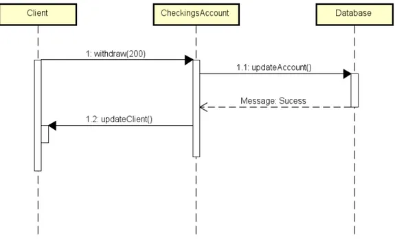
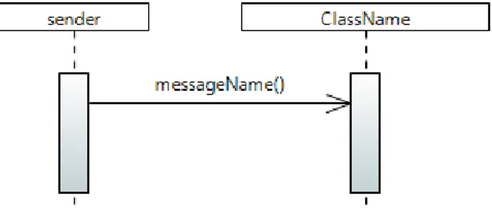
Sequence diagram is the most commonly used diagram for defining software behavior. This includes describing the behavior of several objects within a single use case that is its primary use. Also, based on its name, we can describe it as a sequence of messages that are exchanged between the objects [16]. These interactions are represented in a chronological manner as can be seen in Figure 2.3, that establish behavioral layer for the provided class diagram in Figure 2.1.
Figure 2.3: Sequence diagram example
Each object or actor has a lifeline that goes towards the bottom and each lifeline has activation bars used to represent when the object is in the active state (per-forming some action etc.).
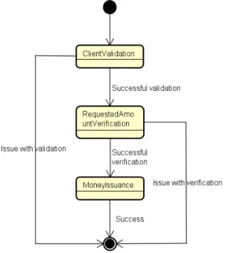
State-machine diagram also known as a statechart is a behavioral type of UML diagram used to represent how a single object behaves within multiple use cases. This basically refers to all the states that an object can have within a system or how different internal and external events contribute to the state change. These diagrams are used for reverse and forward system engineering [16]. An example of the state machine diagram is given in Figure 2.4.
Figure 2.4: State-machine diagram example
2.3
Reactive Objects Language (Rebeca)
Rebeca is an actor-based language with a formal foundation and is created with reason to overcome an existing gap between formal verification approaches and real-world applications. Rebeca is an easy to use JAVA alike language and a modeling language, with formal semantics for models (encompassing their states, state transi-tions, communications and provision of accessible interfaces), and formal verification support [1].
Rebeca combines certain concepts from actor-based modeling with certain concepts from object-based modeling. This indeed implies that Rebeca is used for develop-ing object-based distributed systems that can be formally verified by usdevelop-ing a model checking tool. Notably, Rebeca uses abstraction techniques to reduce the state space of the model in order to make it more appropriate for model checking.
Model checking in Rebeca can be done directly with the use of Rebeca Model Checker (RMC) which is a tool for direct model checking of Rebeca models [17]. Besides, when it is of interest Rebeca can be translated to other model-checker languages among which Promela is the most popular for its model-checker SPIN that is ar-guably one of the world’s most powerful tools for detecting software defects in dis-tributed systems.
In Rebeca [1], computations are established by passing asynchronous messages be-tween Reactive Objects (rebecs) and execution of the corresponding message servers of passed messages. Each message is placed in the queue of the receiving rebec (re-sponsible for handling upcoming messages) and it specifies the method to be called when the message is finally serviced.
More about Rebeca, its semantics and its relation to the Actor-based modeling is provided in the following two sections.
2.3.1 Rebeca - Actor-based Modeling
When we elaborate on Rebeca we find it important to make a comparison with actor-based.
Rebeca model is to some extent similar to the pure actor model based on two of its main concepts:
1. Asynchronous message passing
2. Use of independent active objects
These independent active objects are reactive and self-contained [5]. They are called rebecs that stands for reactive objects. In Rebeca, computations are es-tablished by passing asynchronous messages between rebecs and execution of the corresponding message servers of passed messages. Each message is placed in the queue of the receiving rebec (responsible for handling upcoming messages) and it specifies the method to be called when the message is finally serviced [1].
The queue of each rebec is a buffer used for storing messages in an order in which they will be executed so that the first message that arrives is served first that is based on the First Come First Served (FCFS) scheduling approach. The queue length represents a maximum number of messages that can be stored in a queue and it is defined in the reactive class definition (that is indicated next to the reac-tive class name surrounded by parenthesis).
As aforementioned, we use FCFS scheduling of the messages inside the queue. No-tably, when the message at the top of the queue of the reactive object is serviced then the defined method, in the message, is called, which triggers the removal of the message from the queue [1,17].
2.3.2 Rebeca Syntax and Semantics
As can been seen in Figure 2.5, a list with Rebeca syntax is presented. We are going to discuss briefly the most important concepts among them.
As we already mentioned in the previous sections, each reactive object (rebec) is instantiated from the corresponding reactive class (reactiveclass), and it has a single thread of execution [5,17]. In Rebeca, we have a set of reactive classes and a main part. In the main, rebecs are instantiated from the reactive classes. Furthermore, each of the reactive classes contains known objects (knownrebecs), message servers (msgsrv ) and state variables (statevars) [1]. Known objects (knownrebecs) are actu-ally the rebecs whose message servers can be called by instances of this rebec which basically means that each rebec can send messages (invoke message servers) of the rebecs specified in its parameter list (established when declaring a rebec) [1]. State variables (statevars) are variables which are holding the state of the rebec to which they belong. They can be accessed by the message servers in the same reactive class but not outside of it. The message servers (msgsrv ) are methods responsible for handling the incoming messages. Beside message servers, we also have another type of methods that can be defined and those are known as local methods. As they are local, they can only be called by message servers and other methods within the same rebec. Both message servers and local methods can have input parameters of type
ExtType that includes regular Type. This rebec (or the instantiation of this reactive class) can be accessed (only within) by using a keyword self [1]. This is used by local methods to send messages to the rebec that contains the method. There is another type of variables aside from the variables that are part of the state space (statevars) and these are known as local variables. The use of local variables is self-explanatory as it is expected that we need to isolate certain variables or use them temporarily without a global effect on the class level. Similarly, in JAVA we have both global and local variables that can be comparably mapped with the state space variables and local variables in Rebeca, respectively. A constructor has to be included in Re-beca, in at least one of the reactive classes, as it serves its purpose being the initial message server (containing initial message call), that sets things going. Constructor is used in the initial state as a first message in the queue to be serviced that basi-cally means that constructor will always be executed first. Additionally, it is used to initialize state variables, similarly as in JAVA. A simple example for defining a Rebeca model is provided in Listing 1.
r e a c t i v e c l a s s P r o d u c e r ( 2 ) { k no w nr e be c s { Consumer knownconsumer ; } s t a t e v a r s { b o o l e a n p r o d u c t s e n t ; } P r o d u c e r ( ) { p r o d u c t s e n t = f a l s e ; s e l f . p r o d u c e ( ) ; } msgsrv p r o d u c e ( ) { knownconsumer . consume ( ) ; p r o d u c t s e n t = t r u e ; } } r e a c t i v e c l a s s Consumer ( 2 ) { k no w nr e be c s { P r o d u c e r knownproducer ; } s t a t e v a r s { b o o l e a n p r o d u c t r e c e i v e d ; } Consumer ( ) { p r o d u c t r e c e i v e d = f a l s e ; s e l f . consume ( ) ; } msgsrv consume ( ) { knownproducer . p r o d u c e ( ) ; p r o d u c t r e c e i v e d = t r u e ; } } main { P r o d u c e r p r o d u c e r 1 ( consumer1 ) : ( ) ; Consumer consumer1 ( p r o d u c e r 1 ) : ( ) ; }
3
Related Work
Many research papers have been done on the subject of UML formal semantics and formal verification with hope to define formal interpretations that in some cases go even beyond it. Different approaches have been proposed with similar goals and we will briefly mention the two most common approaches in this field. First is direct UML formalization, and the second is transformation of UML concepts to formal languages where they can be verified by using formal verification tools.
In the first approach mathematical theories are used for formalization of UML. In [18], authors propose a flexible and modular formalization approach based on temporal logic to deal with the lack of well-defined semantics, open to different in-terpretations. It also identifies some of the pitfalls, in many works done, due to the predefined, fixed semantics with limited interoperability, and proposes a modular, flexible semantics able to cope with existing interpretations and highlight the new ones [18]. In [10], authors describe the formalization of the UML meta-model in Slang (that is a formal methods language) while stating that these concepts, they researched in the paper, can be ascribed to any algebraic theory based formal lan-guage. They aim to formalize the whole checking procedure with a goal to present a process in which a UML translation can be formally verified. In [19], authors specify axiomatic semantics for UML (representing classes, associations, instances and general sub-models of UML) that are given in terms of structured theories in a simple temporal logic. These introduced semantics are appropriate for modu-lar reasoning about UML models and they are based on the set-theoretic Z-notation model adopted by Syntropy (that is an object-oriented analysis and design method).
In the second approach, the formal semantics are provided to UML through conceptual mapping followed by a transformation of UML concepts to established formal languages where they can be verified by using formal verification tools. Our thesis can be classified as an effort oriented towards this approach where we aim to bridge the gap between UML and formal verification by providing a mapping procedure of the UML concepts towards Rebeca (that is an actor-based formal lan-guage). Related works for this approach include the mapping between UML models and Object-Z specifications (that is an object-oriented extension of Z-notation and represents a formal specification language for modeling computing systems) [20]. This paper also provides a formal semantic mapping between the two languages at the meta-level, that is responsible for making this transition more systematic. Besides, we have another related research paper regarding a formal method based around Abstract Machine Notation (AMN) or more precisely the transformation of state-machine diagrams towards the AMN of the B method [21]. Notably, B method is a software development methodology grounded on B which is a formal method (tool-supported) and is based on the AMN.
The use of UML profiles to facilitate transition to other domains is one of the most common approaches used for mapping UML to other languages. In the past decade, there have been many UML profiles proposed to OMG [22], and some of
them even became standards. In case of Rebeca and UML, the two research pa-pers [3,5] are also proposing the use of UML profiles for enforcing transition of UML towards Rebeca. However, as we could see from their examples and many other ex-amples that are available, UML profiles are significantly limiting the true potential of UML by creating a domain-specific UML language that is in a way a hybrid be-tween the source UML and other domain-specific languages used as a target. This approach restricts the use of the new hybrid UML to only that domain (language).
Moreover, in the field of modeling reactive systems a lot of work have been done. Related papers cover the modeling of reactive systems by using UML and the trans-formation (generating code) from UML to target languages. For modeling of reactive systems, most research papers propose the use of the state-machine diagrams [14,21]. In [14], a UML profile is proposed for building concurrent reactive systems (that is grounded on state-machine diagrams). In [21], graphical design of reactive systems is introduced which is based on the transformation of state-machine diagrams towards the AMN of the B method. However, as we already mentioned there are two research papers directly related to the transformation of UML to Rebeca that are in fact not proposing the use of state-machine diagrams but a combination of structural and behavioral diagrams where sequence diagrams are used instead [3,5]. These papers clearly justify such decision by stating that Rebeca and its underlying execution mechanisms (based on the actor-based modeling paradigm) are unique and require a different behavioral type of diagram. Notably, state-machine diagrams should only be used to portray the external and temporal events as well as the reaction of an object to them, as stated by different authors. This, however, does not apply in the case of Rebeca where dequeuing a message server and its execution cannot be considered as an external event [3,5].
In this paper, we want to keep the UML in its native form without introducing a UML profile. In addition to that, we need to set some rules that will be used as cor-rectness attributes for validating source UML models before conversion to Rebeca takes place and establish compatibility with the mapping procedure or essentially that we are in Rebeca domain. The combination of these rules implies a design pat-tern for modeling of the considered UML diagrams. Furthermore, we consider both structural and behavioral diagrams as UML models, particularly Class diagram and Object diagram as structural diagrams and Sequence diagram and State-machine diagram as behavioral diagrams. However, as we strive to get the maximum from the provided UML information and reduce the number of diagrams in the process, we primarily focus on three of the mentioned diagrams (Class diagram, Object di-agram and one of the behavioral didi-agrams). Notably, the main differences between this paper and other two papers that also propose mapping between UML and Re-beca [3,5] is in the extensiveness and detailness of the mapping procedure as well as the lack of UML profile. In this respect, the two related papers only provide brief semantical mappings for structural concepts and include partial behavioral concepts without specifying the mappings for them, this work includes detailed conceptual mappings on the syntax level for complete structural and behavioral concepts of Rebeca.
4
Research Process
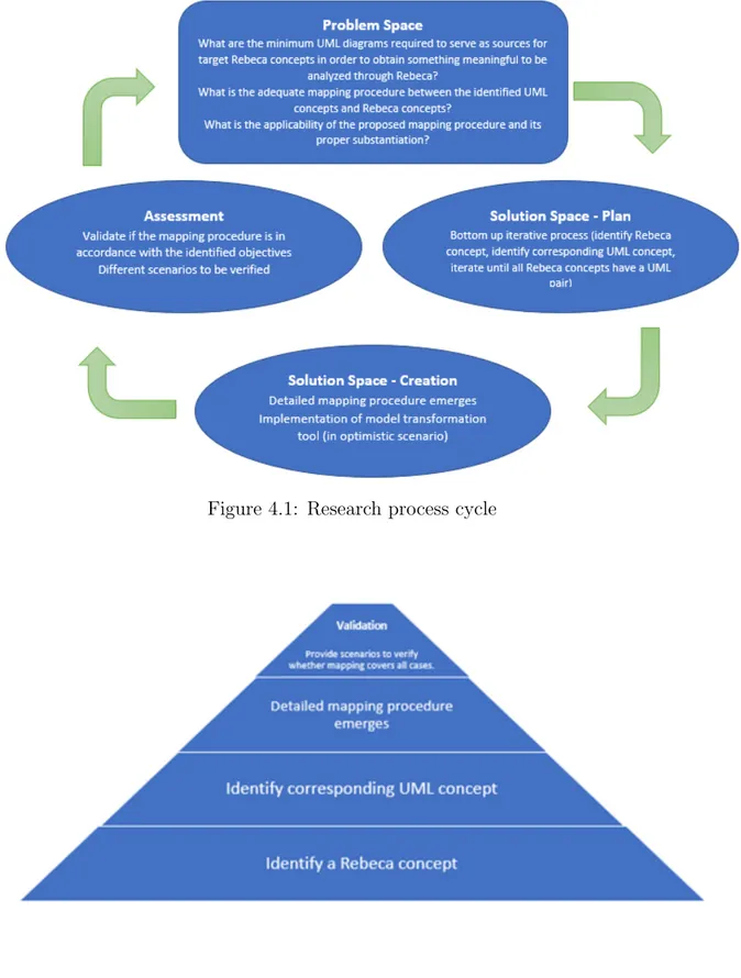
Evaluating the viable ways towards mapping of UML to Rebeca including identi-fication of the required UML diagrams and their consisting information (for such mapping to be achievable) and providing a detailed enough mapping procedure with applicability scenarios to support the given procedure, requires a detailed research design taking into account all these activities that have to be accomplished. Consid-ering this, we defined a clear process that corresponds to the given activities (Figure 4.1). Problem space phase of the research process cycle fully corresponds to the pro-posed research questions that are indeed the main sources of interest and motivation in this thesis. Solution space and assessment parts of the aforementioned process are high-level abstractions and are refined further as a separate process (Figure 4.2), in order to provide a more detailed description of the overall research process. This newly introduced process starts with a bottom-up approach where we first identify Rebeca concepts. Due to the extensiveness of Rebeca and its syntax we consider only Core Rebeca, although we briefly discuss how can Timed Rebeca and Probabilistic Timed Rebeca be modeled in the UML, as part of the potential improvements sec-tion. The next step in the process (Figure 4.2) is for each identified Rebeca concept to identify the minimum information needed to provide in the UML, for the map-ping to be viable. This process is iterative, and it is repeated until all the identified Rebeca concepts have the matching pair in the UML. When this condition passes, as a result, the detailed mapping procedure emerges that will be validated in the final step of the process. The validation phase itself will be an important step in the whole story. It is divided into pre-conversion validation and post-conversion valida-tion, where the latter entirely depends on the success of the former. In other words, the transformation shall not be done until all the correctness attributes from the pre-conversion validation are satisfied. Hence, the validation phase can be described as another important and structured bottom-up process consisting of pre-conversion validation of source models and post-conversion validation of target models (Figure 4.3).
We can define the research to be performed as a descriptive study that is charac-terized by a structured approach where at each stage, we go deeper into the core of the problem from which the descriptive solution emerges. The comprehensive de-scription of the emerged mapping procedure is the main descriptive object, during the research.
Along with it, the identification of adequate validation techniques is the second de-scriptive object.
Figure 4.1: Research process cycle
Figure 4.3: Validation process
Our main research goal is to propose a subset of UML modeling concepts that can be used for modeling the domain of reactive and distributed systems as mod-eled in Rebeca. Besides, this would enable transformation of UML models to Rebeca models and use of its formal verification tool. This mapping procedure is to be used after the design of a software solution is done, using a subset of UML diagrams. Among the many benefits, we mainly strive to cut the production and maintenance time as well as the cost of software solutions through formal verification early in the design process. Moreover, after establishing the correctness of Rebeca models, we can go even further and use model transformation to obtain executable JAVA code from Rebeca models. The overall objective of this thesis is to design the afore-mentioned mapping procedure and provide validation of the source UML models in pre-conversion validation and target Rebeca models in post-conversion validation. The research started with the formulation of research goals which are then investi-gated in the paper, followed by a literature review of papers and articles that focus on UML and model transformations on one side and Rebeca with the inclusion of the mapping between UML and Rebeca on the other side. The next step was a requirements analysis that lead to identification of the requirements based on which we built the conceptual mapping procedure. After the thorough investigation of Rebeca syntax [1,17], we proceeded by extraction of the complete Core Rebeca con-cepts. Afterward, the iterative process for the identification of corresponding subset of UML concepts and potential limitations, with respect to them, was conducted. It is worth mentioning that we used Papyrus modeling environment (in Eclipse) and UML specification for identification and modeling of UML concepts. The overview of the obtained results (comprehensive mapping procedure) is presented in the form of three tables, followed by validation phases including both pre-conversion valida-tion and post-conversion validavalida-tion. Conclusively, we discussed the limitavalida-tions of this thesis and proposed directions upon which future research can be established.
5
A Mapping Procedure for Transformation of
UML Models to Rebeca Models
5.1
Requirements Analysis
As aforementioned, one of the goals is to identify the Rebeca concepts that will be covered in this thesis which requires source models, to encapsulate the required information within them. These source models are represented by the identifica-tion of the corresponding subset of UML concepts. The requirement for selecidentifica-tion of appropriate types of UML diagrams is essential while focusing on reducing their number and at the same time preserving the meaningful information within them that is necessary for mapping to be viable. Hence, we just consider a Class diagram and Object diagram as structural types of diagrams and State-machine diagram and Sequence diagram as behavioral types of diagrams.
The identification and the mapping of target Rebeca and source UML concepts results in the creation of the complete mapping procedure between the observed languages, in an optimistic scenario. However, in a more realistic scenario, when resources (as time) are considered, a line needs to be drawn and a reasonable merit of a detailed enough achievable mapping procedure has to be established. Hence, we consider only Core Rebeca by excluding Timed Rebeca, although we briefly discuss how can Timed Rebeca and Probabilistic Timed Rebeca be modeled in the UML, as part of the potential improvements section. Moreover, we are possibly going to identify certain Rebeca concepts for which there is no matching pair in the source UML or the critical merits as time, cost and complexity of introducing additional types of UML diagrams do not reflect the desired, expected results and objectives. In such situations, we document these cases as limitations of the emerged mapping procedure and we propose a possible solution for them, that is in the scope of the mapping procedure, when applicable. Some of these solutions are deemed as unrea-sonable for the scope of this thesis based on the available resources and objectives. The other requirements of this thesis concern the identification of correctness at-tributes that will be used as a merit of the correctness/compatibility of source UML models in the pre-conversion validation. Here, we need to consider syntactic correct-ness regarding Rebeca concepts and what is possible or not possible to accomplish in Rebeca. Also, closely related merit of correctness is design correctness with respect to the design pattern used to convey the information within diagrams. Neverthe-less, we include this category as part of the syntactic correctness, as it also deals with boundaries of Rebeca language and therefore can be attributed to its syntax. Notably, boundaries in Rebeca implies boundaries in the mapping procedure, hence necessity to equalize the source UML models and establish compatibility with the mapping procedure which inherently erases interpretations and enables to focus on the domain. As a result of the identification of such correctness attributes, we strive to provide definite correctness rules that convey the design pattern for modeling of the considered subset of UML diagrams.
5.2
Identification of Rebeca Concepts
Rebeca syntax and semantics are not explained as part of this section as they are already discussed in Section 2.3.2. This section strictly identifies the Rebeca con-cepts for which we will provide the mapping. These concon-cepts are extracted from the domain [1,17]. Hence, this section is organized as a single part that describes the identification of the sub-portion of Rebeca concepts for which we attempt to provide mapping with corresponding UML concepts.
5.2.1 Extraction and Analysis of Rebeca Concepts
After the analysis is performed, following Rebeca concepts have been identified:
1. Definition of reactive class
(a) Generic: reactiveclass ClassName(queue size) {class body} (b) Example: reactiveclass Producer(2) {...}
(c) Rule: Class name should start with a capital letter.
2. Definition of known rebecs or known reactive objects
(a) Generic: knownrebecs {specification of known rebecs} (b) Example: knownrebecs { Consumer knownconsumer; }
(c) Rule: Each known rebec is defined by a class name followed by the name of the object that is instantiated.
3. Definition of state variables
(a) Generic: statevars {specification of state variables} (b) Example: statevars { boolean productsent; }
(c) Rule: Each state variable is defined by a type (Type excluding ExtType) followed by the name of the variable.
4. Definition of constructor
(a) Generic (without arguments): ClassName() {constructor body}
(b) Generic (with arguments): ClassName(ExtType argument,...) {constructor body}
(c) Example (without arguments): Producer() { productsent = false; self.produce(); }
(d) Example (with arguments): Producer(boolean prodsent) { productsent = prodsent; self.produce(); }
(e) Rule: Constructor is not preceded by any keyword other than the name of the class and it is used for initializing state variables and calling appro-priate message servers. Notably, it is the first message that is executed by each rebec.
5. Definition of message servers
(a) Generic (without arguments): msgsrv MessageServerName() {message server body}
(b) Generic (with arguments): msgsrv MessageServerName(ExtType argu-ment,...) {message server body}
(c) Example (without arguments): msgsrv produce() {...}
(d) Example (with arguments): msgsrv produce(int numberOfUnits) {...} (e) Rule: Message servers accept ExtType for its arguments and, in compare
with local methods, message servers can be accessed from other reactive classes as well.
6. Definition of local methods
(a) Generic (without arguments): MethodName() {local method body} (b) Generic (with arguments): MethodName(ExtType argument,...) {local
method body}
(c) Example (without arguments): produce() {...}
(d) Example (with arguments): produce(int numberOfUnits) {...}
(e) Rule: Local methods accept ExtType for its arguments and in compare with message servers, local methods can not be accessed from other re-active classes. Local methods can be void and return methods.
7. Definition of main
(a) Generic: main {main body}
(b) Example: main { Producer producer1(consumer1):(); Consumer con-sumer1(producer1):(); }
(c) Rule: After the reactive classes are defined, we use main for instantiating reactive classes and passing required arguments and known rebecs which enables the execution.
Moreover, with respect to the building blocks of the message servers, local meth-ods and constructors, or more specifically their behavior and usage, we also identified certain semantics, as follows:
1. Conditional statements (if/else)
(a) Generic: if(condition) {logic if condition is TRUE} else {logic if condition is false}
(b) Example: if(signal2 == false) {...} else {...}
(c) Rule: Conditional statement if can be defined alone without definition of else depending on the outcome that we are trying to achieve. In other words, else is optional. We can nest conditional statements and have a condition inside a condition.
2. Conditional logical operators
(a) Generic: logical AND - condition && condition, logical OR - condition || condition, negation - !condition
(b) Example: logical AND - signal1 == true && signal2 == false, logical OR - signal1 == true || signal2 == false, negation - !signal1
(c) Rule: Conditional logical operators are used for connecting multiple con-ditions inside a single clause with the use of logical AND (&&) and logical OR (||) and to negate the value of a certain condition with the use of negation (! ).
3. Conditional comparisons
(a) Generic: equality comparison - variable == value, inequality comparison - variable != value. Other types: variable < value, variable > value, similarly: <= (less than or equal to) and >= (greater than or equal to) (b) Example: signal1 == true, signal2 != true etc.
(c) Rule: Comparative operators are self-explanatory and do not require additional description.
4. Assignment
(a) Generic: variable = value; (b) Example: signal1 = true;
(c) Rule: Beside this, we can also use following assignment operations +=, -=, *=, /=, %=.
5. Call of message servers (and local methods)
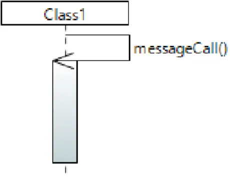
(a) Generic (message server defined in same rebec): self.messageServerName();
(b) Generic (message server from known rebec): knownRebec.messageServerName();
(c) Generic (message server with arguments in same rebec): self.messageServerName(argument,...)
(d) Generic (message server with arguments from known rebec): knownRebec.messageServerName(argument,...)
(e) Example (message server defined in same rebec): self.Passed(); (f) Example (message server from known rebec):
knownconsumer.consume();
(g) Rule: Local methods are not presented. However, the same procedure applies for local methods except that local methods can only be called within the same rebec. This means that only the first case of message server invocation (within same rebec) applies to local methods.
Besides all the semantics that we identified from the provided examples, we will consider some additional Rebeca semantics that are important to provide a mapping for. As follows:
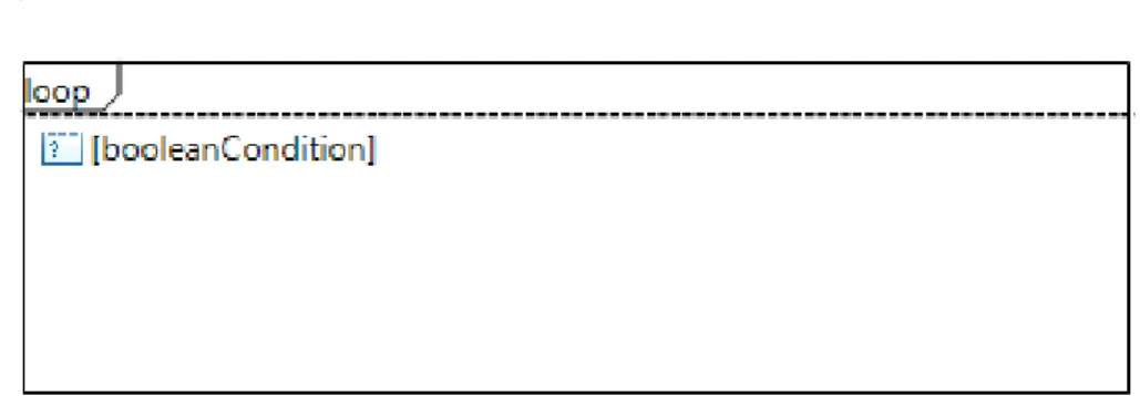
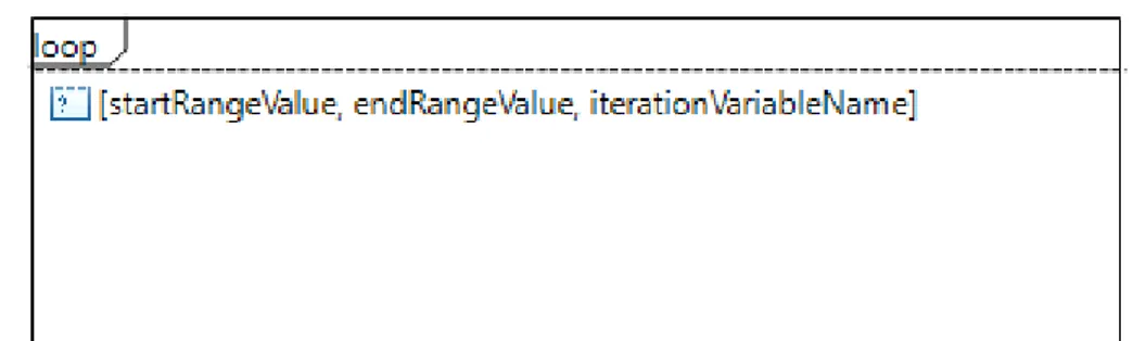
1. Loops (for and while)
(a) Generic (for loop): for(i = 0; i < N; i = i + 1) {loop body} OR for(i = N; i > M; i = i - 1) {loop body}, where N and M are natural numbers and i is iteration variable name
(b) Generic (while loop): while(condition) {loop body} (c) Example (for loop): for(i = 0; i < 5; i = i + 1) {...} (d) Example (while loop): while(i < 5) {...}
(e) Rule: Loop condition can be defined slightly different but the core struc-ture remains the same.
2. Arrays (definition and usage)
(a) Generic (definition): Type [size] variable;
(b) Generic (usage): variable[N] to get the value at the specified array po-sition OR variable[N] = value; to assign the value to the array popo-sition. Notably, N is natural number within the scope of array size (N >= 0, N < variable.length).
(c) Example (definition): int [4] numberArray;
(d) Example (usage): numberArray[0] to get the value OR numberArray[0] = 5; to set the value.
(e) Rule: The arrays can only be of type Type excluding ExtType.
3. Non-deterministic expressions
(a) Generic: variable = ?(value1, value2,.. valueN); (b) Example: signal1 = ?(true, false);
(c) Rule: Value that is passed in the non-deterministic clause can be an expression and it is deemed as valid if it’s value is determined at the compile time.
5.3
Identification of Corresponding UML Concepts -
Itera-tive Mapping
When all the considered Rebeca concepts have been identified and documented we can proceed by providing a corresponding UML concepts that can be used as map-ping pairs in the process of creation of the mapmap-ping procedure. This process is iterative as we iterate both through UML and identified Rebeca concepts and per-form detection of mapping pairs. After the deep analysis of the documented Rebeca concepts is completed, we considered the subset of modeling concepts of the Class
Diagram, Object Diagram and Sequence Diagram, by excluding a State-machine di-agram. This was done with reasons to avoid adding an unnecessary additional layer of complexity that would not significantly benefit the already provided mapping procedure and semantic richness of the other three included diagrams. Moreover, we opt to provide a behavioral richness that is significant and sufficient by the use of only sequence diagram that will be enriched with minor additional concepts, to compensate for the elimination of the State-machine diagram.
We divide this section based on the type of UML diagrams that are used as sources for mapping with identified Rebeca concepts. Hence, we have a separation of structural and behavioral UML concepts and for each of them, a specification of corresponding Rebeca concepts is identified and documented.
5.3.1 Structural UML Concepts
UML structural diagrams are very important for a provision of a skeleton of the modeled system and establishing a connection with Rebeca’s structural blocks. Only two structural diagrams are considered in this thesis and these are class diagram and object diagram. This was done as an attempt towards a minimalist approach for the provision of a detailed mapping procedure as these two types of diagrams provide the exact structural information that is necessary for mapping to be viable and complete. A class diagram is a natural choice of a structural diagram when object-oriented languages are considered which in this case is true as Rebeca uses JAVA like syntax and therefore certain concepts from Object Modeling. Moreover, as Rebeca has a main block in which it instantiates the objects and passes the required known rebecs for all instantiated objects as well as constructor arguments when applicable, we need another type of UML diagram that can serve as a source of information for this cause. Object diagram suits perfectly for this purpose as it lets us to define relations between instantiated objects as well as define the values of constructor arguments when applicable. On the other side, the class diagram could not be used for this purpose as it focuses strictly on modeling the class level layer.
Class Diagram Class diagram and its semantics include the following elements that can be used for mapping with Rebeca concepts in the following manner:
1. Class
(a) Mapped with: Rebeca’s definition of reactive class
(b) Definition of mapping: ClassName−−−−→ reactiveclass ClassName (??queuemapped size??) {class body}
(c) Comment/Limitation: The queue size is not an explicitly available op-tion when setting a class name in the class diagram and we propose two approaches that can be applied here. One is to leave it as it is and define it afterward manually which is not a solution but limitation. The other concerns the definition of the altered class name to accommodate for the queue size, Rebeca property. An example of this is given in the next list
(d) Possible solution: Definition of altered class name in a Class diagram: ClassName[queuesize], or as an example: Producer[2].
2. Attribute
(a) Mapped with: Rebeca’s definition of state variable
(b) Definition of mapping (regular attributes): attributeName:Type[1]−−−−→mapped Type variableName; ENCLOSED by the state space container: state-vars{}. WHERE, attributeName and variableName are the same.
(c) Definition of mapping (regular attributes with default value): attribute-Name:Type[1] = value −−−−→ Type variableName;, PLUS assignment inmapped the constructor: variableName = value;
(d) Definition of mapping (array attributes): attributeName:Type[N] −−−−→mapped Type [N] variableName;, ENCLOSED by the state space container: stat-evars{}. WHERE N>1
(e) Comment/Limitation: Notably, the definition of state variables in Rebeca requires a state space that is defined by statevars{} and inside which the state variables are specified. This means that along with the first state variable, we must also provide state space used as a container for all the upcoming state variables inside the observed class. Regarding the constraints ([1] and [N]), that separates singular variables from arrays, there is a minor limitation here in the UML. This comes from the fact that in order to define an array, the N constraint has to be greater than one (N>1) which therefore excludes the creation of single element arrays. In favor of this approach, we state that there is no logical explanation for the creation of singular arrays, as the main reason for their existence, in the first place, is having a variable capable of containing more than one element.
Additionally, default value for the regular attributes has to be assigned in the constructor and provided for all attributes whose values are statically assigned in the constructor (without dynamic argument passing). The assignment has to be done after the constructor has been generated as part of the operation to constructor mapping, considering that we do not know if the constructor has arguments or not at this point.
(f) Possible solution: Not applicable.
3. Operation/method
(a) Mapped with: Rebeca’s definition of message server or local method or constructor
(b) Definition of mapping (message server): methodName(in parameterName: Type,...) −−−−→ msgsrv MessageServerName(ExtType argument,...) {messagemapped server body}
(c) Definition of mapping (local method): methodName(in parameterName: Type,...):Type −−−−→ ExtType LocalMethodName(ExtType argument,...)mapped {local method body with a return statement of the adequate type}
(d) Definition of mapping (constructor): methodName(in parameterName: Type,...) −−−−→ ClassName (ExtType argument,...) {constructor body}mapped (e) Comment/Limitation: Notably, arguments are optional and the
map-ping remains the same without them, in which case we just exclude them from the mapping. A constructor has to be included in Rebeca, in at least one of the reactive classes, as it serves its purpose being the initial message server (containing initial message call), that sets things going. Additionally, it is used to initialize state variables. The rules for the con-structor arguments are defined in the next mapping. Additionally, there is a limitation regarding a definition of operations in the class diagram with respect to the available Rebeca semantics or more precise definition of message servers and local methods and constructors. This is due to the possibility to have message servers, local methods and constructors in Rebeca that are defined in a different way. However, on the UML side, we have just regular operations defined in the class diagram. Moreover, as we want to avoid introducing Rebeca semantics into the UML we need to find a better way to distinguish between message servers, local methods and constructors, on the UML side, to be able to provide an adequate mapping between these semantics in UML and Rebeca. We identified a possible way to deal with this issue and we document it under the following list item.
(f) Possible solution: We make local methods private in the class diagram (as they are only accessible from the same rebec and can be perceived as the class level methods). On the other side, we leave message servers public. Additionally, when we consider constructors we can notice that they are defined in the same manner as message servers in the class diagram (as public operations), which is problematic. To deal with this issue, we specify that any public operation, whose name is equal (in addition to case sensitive) to the name of the consisting class, is taken as the constructor. Otherwise, it is taken as the message server.
We take this approach for the mapping as it appears to be the most meaningful and simple solution. Public and private markers represent a modeling semantic in the class diagram, that is not expressed in a textual format but graphical (as green plus or a red minus signs at the bottom right corner, respectively).
4. Constructor operation/method argument
(a) Mapped with: Rebeca’s definition of constructor argument and assign-ment to corresponding state variable
(b) Definition of mapping: in parameterName: Type −−−−→ ExtType argu-mapped mentName PLUS assignment in the constructor body to the state
vari-(c) Comment/Limitation: Notably, assigning the argument to the adequate state variable is not straightforward as we need to match the appropriate argument with its corresponding state variable. We identified two possi-ble ways of handling this issue and we present them in the following list item.
(d) Possible solution
i. We add a separate sequence diagram to model the assignment of the arguments to their corresponding state variables. This makes sense as this is how we handle the assignment in local methods and message servers.
ii. We decide on a naming convention for constructor arguments. For example, arguments are named as follows: argumentName = stat-eVariableName + ”Arg” keyword => argumentName = stateVari-ableNameArg
We choose the second approach for this issue with reasons to avoid in-troducing additional complexity that arises with the provision of too many sequence diagrams. Additionally, constructors are not equivalent to message servers and local methods as constructors are used for ini-tializing objects and are invoked implicitly whereas message servers and local methods are used to exhibit functionality of an object and are in-voked explicitly. Also, a sequence diagram is a behavioral diagram while assignment conducted in the constructors is predictable from the aspect of structural diagrams in the UML. On the other side, constructors may exhibit some behavioral aspects as well, but more with respect to invo-cation of message servers that serve as a behavioral initialization of the class level logic in Rebeca. For this part of constructors, we truly need a sequence diagram as it is impossible to represent it in any other way, in a reasonable fashion. These are some of the arguments that go in favor of the selection of the second approach.
5. Association or relation with other classes
(a) Mapped with: Rebeca’s definition of known rebecs
(b) Definition of mapping: associationCardinalityAndName −−−−→ dictatesmapped the number of known rebecs (of the specified type or class from which association is drawn) and the name of instantiated objects
(c) Comment/Limitation: Notably, we could argue if this information should be used for mapping with instantiated objects within known rebecs with reasons that it may not be provided in its adequate form in UML class diagram, that is necessary for mapping to be viable. Most often, only the cardinality is defined in a proper form while the name may not be defined appropriately as the list of comma-separated object names or a single object name (if the cardinality is one). However, we could make an assumption that the consisting information within the class diagram
is modeled accordingly. In any case, we could use this information for es-tablishing correctness or identifying inconsistencies with the information provided elsewhere in the structural or behavioral UML semantics, that could then be used for correctness evaluation of source UML models as part of the pre-conversion validation with respect to these concepts. (d) Possible solution: Not applicable.
Object Diagram Notably, since UML 2.5, there is no explicit specification of Object diagram. But, considering its similarity and close relation with the class diagram (without which it makes no sense for the object diagram to exist), the UML 2.5+ specifies a notation for instances of classifiers. This is essentially the class diagram with the use of specialized modeling elements for representing the instances of the class. Basically, it requires a class diagram from which it will reference the classes and properties, that are instantiated. Moreover, this new definition of the object diagram representation is employed by Papyrus, where instance specifications (both nodes and edges) are used for definition of objects, in the class diagram. As aforementioned, the object diagram is used for mapping with the corresponding Rebeca concepts that are defined as a part of the main. It suits perfectly for this purpose as it enables us to define relations between instantiated objects. Object diagram representation and its semantics include the following elements that can be used for mapping with Rebeca concepts in the following manner:
1. Object name
(a) Mapped with: Rebeca’s rebec name when instantiating a class within main
(b) Definition of mapping: objectName: ClassName −−−−→ ClassName ob-mapped jectName():(); , ENCLOSED by the main block
(c) Comment/Limitation: The definition of the main or enclosing main block is not exactly the part of the mapping but will be created with the first mapped object as the container that all subsequent objects from the object diagram will use.
(d) Possible solution: Not applicable.
2. Object argument
(a) Mapped with: Rebeca’s definition of constructor argument when instan-tiating a class within main
(b) Definition of mapping: attributeName:Type[N] = argumentValue −−−−→mapped ClassName objectName():(argumentValue); , ENCLOSED by the main block
(c) Comment/Limitation: The definition of the main or enclosing main block is not exactly the part of the mapping but will be created with the first mapped object as the container that all subsequent objects from the ob-ject diagram will use. Nonetheless, the definition of mapping shows how