V¨
aster˚
as, Sweden
Thesis for the Degree of Master of Science (60 credits) in Computer
Science with Specialization in Software Engineering 15.0 credits
A FORMAL ANALYSIS FRAMEWORK
FOR EAST-ADL ARCHITECTURAL
MODELS EXTENDED WITH
BEHAVIORAL SPECIFICATIONS IN
SIMULINK
Paolo Shestani
psi17001@student.mdh.se
Vasja C
¸ ollaku
vcu17001@student.mdh.se
Examiner: Professor Marjan Sirjani
M¨
alardalen University, V¨
aster˚
as, Sweden
Supervisor: Post Doc. Raluca Marinescu
M¨
alardalen University, V¨
aster˚
as, Sweden
Abstract
Model-Driven Development is a development approach which is being used frequently in the auto-motive context in order to design models. EAST-ADL is an architectural language which models systems according to their architectural features, whereas Simulink is a tool environment which mod-els systems according to their behavior. In this thesis work, we propose a set of transformation rules that take into consideration the EAST-ADL architectural model details and the behavioral specifi-cations in Simulink, and generate a formal model, which can be verified UPPAAL model checker. Moreover, we implement these proposed transformation rules in a tool that automates them. The transformation rules proposed in this thesis work would be implemented for every EAST-ADL file with Simulink behavior specifications, generated by the MetaEdit+ tool. Properties like timing con-straints, triggering and hierarchy in both EAST-ADL and Simulink have been considered by the transformation rules. Finally, the Brake-by-Wire case study is used to validate the tool and assess the mapping of the elements.
Acknowledgments
The most important gratitude belongs to our supervisor, Raluca. Thank you, Raluca! We started this journey together in a peculiar way and we did not make it any easier for you, but you still helped us and guided us through everything. You did not gave up on us and was a real mentor.
Thank you professor Elinda! You had faith in us and believed that we would make it, and we did not let you down. You lead us toward a bright future and will always be grateful to you!
Thank you Mlardalen University! It was an amazing experience being a student here. We are thankful of what you taught us and the opportunities that you offered us, so we hope to have made you proud and that we can be good ambassadors.
A more personal touch...
I would like to express my very profound gratitude to my family for providing me with unfail-ing support and continuous encouragement throughout my years of study and through the process of researching and writing this thesis. This accomplishment would not have been possible without them. Thank you. - Paolo Shestani
Thank you mum and dad and chuli! You are the only ones who have my heart. Thank you for walking this path with me. It has always been the four of us and that is the thing I am most grateful of. I am who I am today just because of you. I love you. Thank you Odeta for being a cousin, a teacher, a supervisor, a guider. You were a lighthouse when I was in the shadows and that, I shall never forget. Last but not least, I thank myself. Good job, Vasja, you did it! Now, go and conquer the world. - Vasja C¸ ollaku
Table of Contents
1 Introduction 8
1.1 Problem Formulation . . . 9
2 Related Work 10 2.1 Formal Analysis of EAST-ADL models . . . 10
2.2 Formal Analysis of Simulink models . . . 10
2.3 Reflection on the state-of-the-art of formal analysis of EAST-ADL and Simulink models . . . 11 3 Preliminaries 12 3.1 EAST-ADL . . . 12 3.1.1 EAST-ADL Notations . . . 12 3.1.2 Modeling Tool . . . 13 3.2 Simulink . . . 14 3.2.1 Simulink notations . . . 15 3.3 Model Checking . . . 15
3.3.1 Timed Automata Notations . . . 16
3.3.2 UPPAAL . . . 17
4 Research Method 20 4.1 Research Method steps . . . 20
4.2 Threats to Validity . . . 22
5 Transformation Rules 23 5.1 Proposed Transformation Rules . . . 23
5.2 Hierarchy . . . 26
5.2.1 EAST-ADL without hierarchy . . . 26
5.2.2 EAST-ADL with hierarchy . . . 26
5.2.3 Simulink without hierarchy . . . 28
5.2.4 Simulink with hierarchy . . . 28
5.3 Additional information . . . 29
5.4 Proposed Transformation Rules applied on examples . . . 30
5.4.1 On the example of a system composed of two sequential FunctionPrototypes of a system . . . 30
5.4.2 On the example of a system with Simulink hierarchy . . . 31
5.4.3 On the example of a system with EAST-ADL hierarchy . . . 32
5.4.4 On the example of a system with event triggering and multiple instantiations of a FunctionType . . . 33
6 Tool Implementation 47 6.1 First tool development . . . 47
6.2 Final tool development . . . 47
7 Brake-by-Wire Case Study 50 7.1 A short introduction to the Brake-by-Wire case study . . . 50
7.2 An insight on the utilized Brake-by-Wire case study . . . 50
8 Results 58 8.1 The tool validation with a simple, small-scale system . . . 58
8.2 The tool validation with a small-scale system with Simulink hierarchy . . . 58
8.3 The tool validation with a system with EAST-ADL hierarchy . . . 59
8.4 The BBW case study validation . . . 59
10 Conclusion 76 10.1 Limitations . . . 76
11 Future Work 77
List of Figures
1 An overview of EAST-ADL Abstraction Levels . . . 13 2 Representation of EAST-ADL notations. . . 14 3 Simulink model of a system whose behavior is represented by atomic blocks . . . . 16 4 The light system model in UPPAAL . . . 18 5 Syntax declarations of the light system model in UPPAAL . . . 18 6 The methodology used in the thesis work . . . 20 7 A template of the network of TA produced by the transformation rules for a simple
EAST-ADL model, with behavioral specifications in Simulink . . . 23 8 A template of the network of SystemInterfaceComponent TA produced by the
trans-formation rules for a hierarchical EAST-ADL model, with behavioral specifications in Simulink . . . 26 9 A template of the network of TA produced by the transformation rules for one of the
subsystems which comprise an EAST-ADL model, with behavioral specifications in Simulink . . . 27 10 A network of SystemBehavior TA generated by the transformation rules on an
EAST-ADL model with hierarchical behavioral specifications in Simulink . . . 29 11 First example system, modelled in EAST-ADL with behavioral specification in
Simulink . . . 34 12 The network of TA produced by the transformation rules for the first example . . 35 13 EAST-ADL and Simulink specifications for the system depicted in the second example 36 14 The network of TA produced by the transformation rules for the second example
for the first FunctionPrototype . . . 37 15 The network of TA produced by the transformation rules for the second example
for the second FunctionPrototype . . . 38 16 EAST-ADL specifications of the third example system . . . 39 17 SystemInterfaceAverage TA of the third example . . . 39 18 The network of TA produced by the transformation rules for the third example for
the first FunctionPrototype . . . 40 19 The network of TA produced by the transformation rules for the third example for
the second FunctionPrototype . . . 41 20 The network of TA produced by the transformation rules for the third example for
the third FunctionPrototype . . . 42 21 EAST-ADL specifications of the fourth example system . . . 43 22 The network of TA produced by the transformation rules for the fourth example
first FunctionPrototype . . . 44 23 The network of TA produced by the transformation rules for the fourth example
second FunctionPrototype . . . 45 24 The network of TA produced by the transformation rules for the fourth example for
the third FunctionPrototype . . . 46 25 The graphical user interface of the implemented tool . . . 47 26 The architecture of the tool . . . 49 27 The Brake-by-Wire use case modelled in EAST-ADL through the MetaEdit+ tool 52 28 The Timing model of the Brake-by-Wire use case modelled in EAST-ADL through
the MetaEdit+ tool . . . 53 29 The Behavior graph of the Brake-by-Wire use case modelled in EAST-ADL through
the MetaEdit+ tool . . . 54 30 Simulink model of the BBW system . . . 56 31 The Simulink behavior of each FunctionType . . . 57 32 Pictures that exhibit the verification of ’not deadlock’ query in the first model . . 62 33 Pictures that exhibit the verification of the second example . . . 63 34 Pictures that exhibit the verification of the third example . . . 63 35 The network of TA generated for HW BrakePedalSensor FunctionPrototype . . . 64 36 The network of TA generated for LDM BrakePedal FunctionPrototype . . . 65 37 The network of TA generated for BrakeTorqCalc FunctionPrototype . . . 66
38 The network of TA generated for HW RREncoder FunctionPrototype . . . 67
39 The network of TA generated for LDM RRSensor FunctionPrototype . . . 68
40 The network of TA generated for GlobalBrakeController FunctionPrototype . . . 69
41 The network of TA generated for ABSatRRWheel FunctionPrototype . . . 70
42 The network of TA generated for the Simulink subsystems of ABSatRRWheel Func-tionPrototype . . . 71
43 The network of TA generated for LDM RRBrake FunctionPrototype . . . 72
44 The network of TA generated for HW RRBrake FunctionPrototype . . . 73
45 Pictures that exhibit the verification of the first example . . . 74
List of Tables
1 Light system properties verified by UPPAAL . . . 19 2 List of FunctionTypes and FunctionPrototypes in the BBW model . . . 55
1
Introduction
Model-Driven Development (MDD) [1] has been proposed as an effective way of managing system complexity and providing a basis for high-quality design and implementation of large scale systems. It mostly focuses in constructing software models before code is generated in order to reduce the amount of work done by developers and have a better planning phase of the projects.
Model transformation and traceability between different levels of abstraction make it possible to model complex systems starting from high level system architecture, specified in architectural modeling languages like EAST-ADL, AADL, SysML, proceeding with the implementation, repre-sented through code generated from models of tools like Simulink, Scilab, IEC 61131-3 etc.
High level system architecture [2] refers to the representation of a system depicting the high level structures which it is composed of. These structures portray different features of the system, providing an outline of it, along with information on how the structures interact with and relate to each other. EAST-ADL [3] is an architectural description language which provides design artifacts of system models, by capturing information like functions, timing, triggering. MetaEdit+ is the tool chosen for this thesis work which implements the EAST-ADL language. EAST-ADL language has notations only for structural elements, and it has no notation for the behavioral information. However, the language allows for the model to be extended with a set of additional models that describe the behavior of the EAST-ADL components. These additional models can be created using other tool, for example Simulink.
Simulink [4], a MATLAB extension, is a graphical programming environment which applies the concepts of Model-Driven development in the modeling, simulation, verification and code gen-eration of dynamic systems. One of its main functionalities is the modeling and simulation of time-dependent system component behavior, which is used by EAST-ADL language to extend be-havioral specifications of the modeled system.
Beyond planning, modeling and developing in the engineering field, an important concept that we will focus a lot in this thesis is model checking. Model checking [5] refers to the technique of formally verifying the correctness of the modeled system by exhaustively exploring the model, in order to reveal unexpected possible interactions between components of the systems model, and hence reveal potential flaws in the actual system. The model checker needs a requirement/prop-erty, formalized as a TCTL query, for it to exhaustively explore the model to decide if the property is satisfied or not. Systems nowadays are becoming more and more complex, thus model checking is becoming crucial in industry for safety and economical reasons. Each tool, implementation or system is virtually model checked before “coming to life”. It is checked whether the upcoming system is going to fulfill all the predefined requirements. It checks if it is safe to use, and tries all the possible scenarios of using it first in a virtual environment and then in a real life example. UPPAAL [6] is a model checker used to model, simulate and verify real-time systems modeled as timed automata, developed as a joint effort between Uppsala University, Sweden and Aalborg University, Denmark.
In this thesis work, we take the high-level EAST-ADL architectural model together with all the Simulink behavioral model and we transform them into a network of timed automata that can be model checked with the UPPAAL verification tool. The goal of our work is to come up with some valid transformation rules and automate the transformation of the input EAST-ADL files into UPPAAL readable files by implementing this transformation chain in a tool. This is an issue that has not been addressed before. Up to our knowledge, some research work and minor de-velopments have been made in this field regarding EAST-ADL transforming into Timed Automata. The ongoing pursuit for advanced embedded system technology and safety improvements has made the “bywire” systems gain ground in machine manufacturing. Its origins are found in air craft and military designs, however nowadays it is a trend in autonomous vehicle manufacturing. The flexibility and optimization this technology brings, together with the energy savings and
sim-plicity in installation are some of the main advantages. It is the electric components that this technology brings that control the brake pressure, instead of any hydraulic fluid. Thus, we have chosen a Brake-by-wire case study to support the work and to validate our thesis work.
The remainder of the report is organized as follows. The following subsections provide a back-ground on this thesis work and take a further look into the goal of this thesis work. Section2gives an overview on the state-of-art of this topic and identifies gaps in the existing work. Section 3 presents the reader with the basis for getting familiar with the languages and tools used in this thesis work. Section 4 outlines thoroughly the research methodology and development approach used to conduct the thesis work. Section 5 elopes the proposed transformation rules, followed by Section 6 where the tooling implementation effort of automating the transformation rules is described. The Brake-by-Wire case study is explained in Section7. Section8describes the results of the case study, which are later discussed in Section 9. The conclusion of the thesis work and future work are explored in Section10and 11, respectively.
1.1
Problem Formulation
The combination of an EAST-ADL model and the set of corresponding Simulink models provides an integrated system model that encapsulates different information about the system. EAST-ADL provides information about the structure of the system and extra-functional constraints (execu-tion time, end-to-end deadlines), whereas Simulink provides informa(execu-tion about the behavior of the components. To provide evidence about the correctness of the design of the system, both repre-sentations need to be merged and transformed into a formal model that can be subject to formal (exhaustive) verification. Timed Automata is the chosen formal model and UPPAAL serves as the formal verification tool.
The main focus of the paper is to provide a verification framework based on UPPAAL for EAST-ADL models extended with behavioral specifications in Simulink. In order to implement this framework, we need to implement a transformation from the EAST-ADL and Simulink model to a network of timed automata, transformation that takes into account the following:
• Both EAST-ADL and Simulink are hierarchical models, while timed automata is a flat model, thus the transformation rules should provide a flattening algorithm that preserves the seman-tics of the original model;
• The verification is done on the timed automata model and not on the original model, thus a traceability mechanism should be put in place to ensure that any error found in the formal model can be traced back on the original model;
• To avoid the state space explosion problem, the transformation should also include different modeling choices that could reduce the state space during exhaustive verification.
The proposed transformation will be evaluated on an industrial use case, called the Brake-by-Wire prototype. Different functional and timing requirements are verified with UPPAAL model checker.
2
Related Work
This is not the first time that research has been conducted towards the analysis of industrial systems modeled in EAST-ADL and Simulink specifications, due to: (i) the increasing interest of automotive companies in EAST-ADL and (ii) Simulink being the de facto modeling tool for automotive systems. In order to present the related work, we divide our literature review into two parts that will reflect previous investigations on the formal analysis of EAST-ADL and Simulink models, respectively.
2.1
Formal Analysis of EAST-ADL models
Closely related to our work, Marinescu et al. [7] present different analysis techniques for EAST-ADL architectural models. They propose the transformation of EAST-EAST-ADL models into Simulink, which are later model-checked in timed automata semantics. UPPAAL SMC is used as a tool to statistically model-check the models and afterwards, these frameworks are applied on the industrial Brake-by-Wire use case. Another relevant contribution in the formal analysis of EAST-ADL mod-els is made by Kang et al. [8]. In this paper, a model-based approach that links the architectural models with component-aware model checking is proposed, together with a description of the tool that gives support to this called ViTAL. EAST-ADL models are expressed in timed automata, in terms of functional and timing behavior of each function block, together with the interactions between function blocks. The timed automata models can then be formally verified with UPPAAL PORT [9]. Furthermore, it is described how the presented methodology proves the real-time and behavioral requirements of EAST-ADL system model. However, unlike [7] and [8], we focus on EAST-ADL models that have hierarchy, and in which the behavior of each component is modeled in Simulink.
Mallet et al. [10] present an approach where UML MARTE is used to define EAST-ADL timing requirements, whereas Feng et al. [11] propose an approach to transform the EAST-ADL augmented behavioral model in a SPIN model for formal analysis. Qureshi et al. [12] explore a re-lationship between EAST-ADL and timed automata, by proposing a template mapping scheme for automated transformations between EAST-ADL models and model-checking tool with timed au-tomata notations, as a contribution to the model-driven development of the automotive embedded system.
2.2
Formal Analysis of Simulink models
Filipovikj et al. [13] propose the transformation of Simulink blocks into stochastic timed au-tomata, that can be formally analyzed with UPPAAL SMC. The transformation is automated in a tool called SIMPAAL and it is later applied in a Brake-by-Wire industrial use case system. The CheckMate tool [14] is another tool that transforms Simulink models in a class of hybrid au-tomata. However, many limitations condition its scalability to complex industrial cases. Yang et al. [15] present an effective toolkit, evaluated in different industrial applications, which translates Simulink Stateflow models into UPPAAL timed automata. In addition, Kekatos et al. [16] have presented a methodology for the transformation of simulation models like Simulink in a network of timed automata, described in SX format. They make use of two tools to facilitate the process of constructing the verification model and apply a new hybridization model for blocks not trans-lated correctly. Agrawal [17] describes an algorithm which carries out the translation of Matlab’s Simulink and Stateflow models into equivalent models of hybrid automata using a tool which is based on metamodel graph transformation, to allow for these models to be verified by verification tools without providing concrete means to conduct the formal verification. Tools for translating Simulink models to different model checkers have been carried out in various works like the work by Meenakshi [18], which introduces a tool that acts as a translator of discrete Simulink blocks to the open-source model checker NuSMV.
2.3
Reflection on the state-of-the-art of formal analysis of EAST-ADL
and Simulink models
Despite the various and abundant work that has been conducted related to our topic, there is scarcely any work on the formal analysis of EAST-ADL architectural models, extended with be-havioral specifications in Simulink. Kang, in [19, 20, 21, 22] extends the work started in [8] on translating EAST-ADL models to UPPAAL by including support for Simulink and validating the set of rules and mapping strategies in automotive case studies.
We present in this thesis work a formal framework that goes beyond the current state-of-the-art in the transformation of both EAST-ADL and Simulink models into a formal model to be verified with UPPAAL timed automata. However, we must highlight that the transformation proposed in this thesis builds upon the works of Marinescu et al. [7] and Filipovikj et al. [13] and requires a new way of expressing the transformation rules that takes into account the formal integration of EAST-ADL with Simulink. To our best knowledge, we present the only approach of formally verifying models with both EAST-ADL and Simulink specifications.
3
Preliminaries
In this section, we provide a basis for understanding the languages and tools used in this thesis work, by briefly explaining their basic concepts, which include the notations of EAST-ADL architectural language, Simulink tool and UPPAAL model checker that are relevant to our work.
3.1
EAST-ADL
EAST-ADL[3] is an architecture, domain-based language which provides early design artefacts of integrated system models, by capturing structure information like functions, timing and triggering. It is assisted by EAST-ADL Association [23], a non-profit, non-governmental organization which undertakes the maintenance and refinement of the language.
In the automotive domain, the late incorporation of complex functions can lead to critical failures that can be left undiscovered in the final product. Due to such potential problems, in the automotive industry the safety standard ISO26262 [24] has been introduced. In this context, EAST-ADL and similar architectural models being developed for the automotive embedded sys-tems, should be integrated in the automotive development practice to ensure the fulfillment of this kind of safety standards and to provide a level of quality of service. Since automotive products contain many safety-critical subsystems, it is desirable to properly verify their correctness, espe-cially at the early stages of development. For this, in the model-driven development context, it is needed to transform the architectural model to an executable formal model that can be exhaus-tively verified.
The system features described by EAST-ADL (structures, execution times, deadlines, func-tions, software and hardware components, variability, requirements etc.) are explicated in four ab-straction levels: Vehicle, Analysis, Design and Implementation level, where each abab-straction level represents specific system analysis during the development process. A more thorough explanation of EAST-ADL abstraction levels is overseen in Section3.1.1. EAST-ADL complements AUTOSAR [25] standard by conforming to its representation of software architecture and hardware implemen-tation details. It is in the lowest abstraction level, the Implemenimplemen-tation level, where AUTOSAR defines the elements to represent the software architecture and its implementation to the hardware. EAST-ADL serves as a framework for modeling systems, supporting all activities of the auto-motive embedded system development. Additionally, its modular attributes allow the support of structural modeling.
3.1.1 EAST-ADL Notations
EAST-ADL meta-model depicts engineering information of the system by covering it in four ab-straction levels, as depicted in Figure1.
Components of the higher levels are decomposed into detailed elements in lower levels, by giv-ing modelgiv-ing context and ensurgiv-ing relation between adjoingiv-ing levels. The Vehicle level describes what the system features are, whereas the other three levels describe how these features function at different detail levels.
The Vehicle level, through TechnicalFeatureModel, describes externally visible features of the ve-hicle. Those features are defined in Analysis level, including FunctionalAnalysisAchitecture, where abstract functional definitions of the vehicle properties are represented, avoiding implementation details. This is decomposed in Design level by the SoftwareDesignArchitecture and Hardware-DesignArchitecture, which represent the software architecture allocated to hardware topology and detailed function designs. The Implementation level contains detailed software architecture and ComponentPrototypes of the hardware, represented by AUTOSAR elements. Nevertheless, all ab-straction levels depict a complete embedded system with traceability relations between them.
Figure 1: An overview of EAST-ADL Abstraction Levels
Furthermore, the system model interacts with two entities: Environment Model and Exten-sions. The Environment Model captures the environment behavior and represents the relevant elements that interact with the system, in the environment context. It is applied across all ab-straction levels and its interaction is supported by the model structure. The Environment Model is needed for verification and validation during all the stages of modeling and developing the system. Extensions cover concerns like requirements, timing, safety/ISO26262, variability, behavior, etc., organized according to the abstraction level.
Functional component modeling is used to model system features at different analysis levels. The main components are functions, which are described by different features like name, descrip-tion, dependencies, constraints, etc. Constraints act as restrictions used to ensure the correct use of the element. Functions are represented by FunctionType at each level, which abstracts functions types used in the system functional structure modeling. The instantiation of a Function-Type results in FunctionPrototype, which is executed based on the “read-execute-write” semantics. Each FunctionType is associated with FunctionBehavior and FunctionFlowPorts. FunctionBe-haviour represents the behavior of the component. Behavioral representation tools, like Simulink or UPPAAL PORT timed automata [8], are used commonly. FunctionFlowPorts are ports used in component interaction. They can act as input ports, allowing the reception of the data, or as output ports, allowing the transmission of data. In order for functions to interact with one another, they are connected at their respective ports through connectors. FunctionConnectors are created between two FunctionPrototypes; they ensure intercommunication and indicate that the connected elements exchange signals. FunctionTrigger defines the triggering of the component behavior and can be either event-based or time-based. A graphical representation of these notations is depicted is Figure2. EAST-ADL provides support to requirements (conditions to be met), verification and validation (through VVCases), timing and generic constraints, etc.
3.1.2 Modeling Tool
There are a set of tools that apply the EAST-ADL language: EATOP [26], PAPYRUS [27], MetaEdit+ [28], VSA [29], MagicDraw [30], SystemWeaver [31]. In this thesis work, we have cho-sen to work with MetaEdit+ as the modeling tool for EAST-ADL.
edit-Figure 2: Representation of EAST-ADL notations.
ing, manipulation of architectural models of systems, using EAST-ADL language and complying with its standards. The main drawback of MetaEdit+ is that it is a commercial tool rather than open source.
Its graphical user interface is resourceful, allowing the use of available libraries and icons. The versatile nature of code generation allows a quick and clear model definition. MetaEdit+ has an advantageous graphical representation of the system, lacking in many other architectural model tools. It acts as its own tool rather than a plug-in for other developing environments as it provides a wide variety of modeling and integration capabilities, which include: EAST-ADL XML inter-change format, tool specific formats (Simulink, UPPAAL), programmable API that makes possible the integration with other programming environments, availability for Eclipse (as a plug-in) and Visual Studio (as an extension), etc. Its environment allows two versions: workbench (where the developers design and use personalized modeling languages) and modeler (where developers use modeling languages). It offers means to support language concepts (defined in the metamodel), constraints, checking rules, notations (to annotate errors) and generic and timing constraints are easily added.
MetaEdit+ allows working on several projects simultaneously, where data sharing between dif-ferent projects is possible. Moreover, it supports various modeling languages except EAST-ADL, like UML, GOPRR, CPL, etc.
Despite all this, the EAST-ADL language does not include notations to explicitly specify the behavior of the components. Such a behavior can be defined with external tools, such as Simulink.
3.2
Simulink
Simulink [4] is a graphical programming environment, developed as a MATLAB extension, which applies model-driven development and model-based design in the modeling, simulation, verification and code generation of dynamic systems. Its main functionalities are the modeling and simulation of time-dependent system component behavior, testing the system under troublesome and complex circumstances by generating tests automatically, inspecting if requirements have been met, certi-fying to standards (ISO 26262 [24]), etc. It investigates complex systems by designing graphical models using the block diagram notation and then simulating a time-dependent system represented
by the model. This user-friendly graphical interface visually aids in the designing of the model by allowing block components to be configured accordingly. They are inserted using the drag and drop mouse operation whereas the simulation can be started, paused and stopped interactively from the Simulink Editor “‘Run simulation button” and results are displayed in real time. Since the results can be seen while the simulation is running, the user can go back and forth through the simulation to analyze the behavior of the system components and identify peculiar situations and errors.
Simulink supports the simulation of a broad range of analog, digital, mixed signal and multi-rate systems, together with linear and nonlinear systems, static and dynamic conditions. Its features allow it to explore the behavior of a variety of systems such as electrical, braking, thermodynamic systems. Due to the shift of the automotive industry towards model-based development [32] after some recent technological advances, Simulink has taken the place as the state-of-practice environ-ment and impleenviron-mentation language in the developenviron-ment process of automotive industry. Moreover, Simulink is compliant with AUTOSAR [25] standards, which are predominantly used in the auto-motive industry in the development of software architecture for electronic control units. Integration with MATLAB allows an ease of share of information between the two programs.
3.2.1 Simulink notations
Let us take a further look into Simulink notions. A Simulink system is a graphical representation of mathematical equations which link the output to the input(s).
Systems are built using blocks. Blocks consist of some functionality and an arbitrary number of ports. Simulink provides the user with a set of predefined block libraries to browse from. They represent the main behaviors that a Simulink system can have such as:
• Continuous - function blocks such as Derivative and Integrator • Discrete - function blocks such as Unit Delay
• Math Operators - function blocks such as Sum, Gain and Product • Signal attributes - function blocks such Data Type Conversion • String - function blocks to manipulate strings
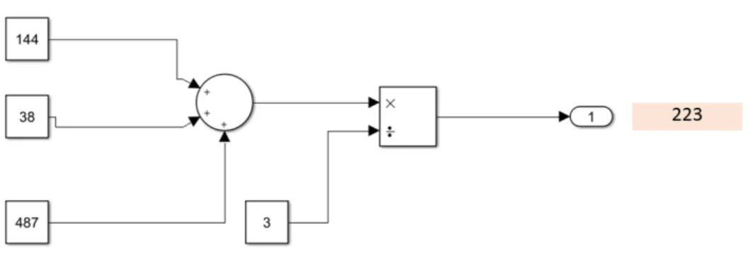
Nevertheless, the blocks can be custom-made through S-functions block written by the user in C, C++, Fortran, Matlab, and Block Models written in Simulink, which enclose their logic from the user. The library blocks that act as a single unit with single operations are called an atomic block. Figure3depicts a simple model designed in Simulink, where the behavior is represented by the atomic blocks of Sum and Product. The model measures the average number of three integer inputs given by a user and displays the result in the screen.
However, a block can consist of a set of atomic blocks and/or other subsystems. A subsystem block is used to structure the model hierarchically. It contains a subset of blocks within the model that have some functionality. During the execution of the system model, all blocks within a subsystem block are executed before moving on to the next block. The subsystem block can be either virtual or non-virtual subsystem. Virtual subsystems have their content flattened to the level of the parent system, whereas non-virtual subsystems have their content computed at once as a single unit (atomic execution). Connections between system blocks are done through an arrow and are used to link the block ports to pass data between them.
3.3
Model Checking
Timing behavior is critical in many real-time systems, such as vehicle airbag deploy system, brake-by-wire automotive technology, etc. The behavior of these systems is time constrained from event to response down to the order of microseconds or less. Thus, the specified time constrains (dead-lines) must be guaranteed to be met as safety issues arise. This brings the issue of model checking
Figure 3: Simulink model of a system whose behavior is represented by atomic blocks
the correctness of every modeled system with regard to time constrains. This is done by verifying if the timing behavior of the system complies to the timing requirements. Consequently, systems are modeled as parallel finite state machines with timing properties called timed automata [33].
UPPAAL [34] is a tool designed to verify real-time systems modeled as networks of timed automata.
3.3.1 Timed Automata Notations
A timed automaton (TA) [33, 35, 36] is a finite automata augmented with a set of real-valued clocks. With timed automata, we can model timing properties of real-time systems and verify their behavior.
Syntax The system is modeled as a network of timed automata, composed of different au-tomata. Each automaton is composed of locations and edges, allowing the change from one location to another. Every automaton has an initial location, which acts as the primary location where the execution starts from. A location can be of three types: normal, urgent and committed. A location is made urgent when no time must be passed in it by the system. The same applies to committed locations, with the provision that the following transition must include an outgoing edge of the committed location. Certain constraints can be put to the system locations and edges by compar-ing the clocks values to time constants, in order to control possible behaviors that the automaton shows. Invariants are conditions put on locations, that act as constraints on the system behavior defining when the system can be in a specific location. When the invariant evaluates to false, the system must leave that location. Guards are conditions put on edges that need to be true in order for the change from one location to another to be possible. Updates on the guard variables can be achieved in edges with simple assignments (a=5) or through a C function (a=f(5)). Additionally, synchronization channels are annotated in complementary labeled edges. Synchronization chan-nels refer to chanchan-nels labeled as ChannelName! or ChannelName?, where the ChannelName! (the inciter) tries to sync with the ChannelName? channel (the reception). Broadcast channels apply the same principle, but for the fact that one ChannelName! channel triggers many ChannelName? channels.
state is defined as the actual location of the TA in the system jointly with the values of all vari-ables of the system. From the initial state of the automaton, two types of transitions can be made: action transition and delay transition [37]. An action transition is undertaken when the current clock satisfies the guard on the corresponding edge, enabling the edge and immediately moving on to the following state. In the case of action transitions, the value of the clocks can be affected by resets on the clocks, if present, otherwise no change happens on them since the transitions are instantaneous. A delay transition delays the automaton for some amount of time by increasing the (synchronous) clocks values with the same amount of time, respecting the current location invari-ant. Delay transitions are not bounded and they can delay the running of the system up to infinite. The system (the abstract model of a timed system composed of as states and transitions be-tween states) starts with values of the logical clocks initialized with zero. The clocks keep track of the time passed when timed automata is running. They can be started and checked independently of one-another and their values can be increased with the same speed. Each state transition can independently set to zero one or more clocks.
Extensions like stopwatches, real-time tasks or cost functions have been largely studied. There have already been developed a few verification tools to input and analyze timed automata, including the model checkers UPPAAL[38] and Kronos[39]. However, they are still academic research tools. 3.3.2 UPPAAL
UPPAAL[6] is a model-checker tool; it is used to model the dynamic behavior of systems by ana-lyzing and simulating the resulting models, where real-time information about the system can be modeled as well. It was jointly developed by Aalborg University in Denmark and Uppsala Uni-versity in Sweden. UPPAAL uses the timed-automata notations to model systems. It was chosen as the model-checker tool for this thesis work due to its straightforward graphical user interface, simplicity of use, efficiency and the short learning curve.
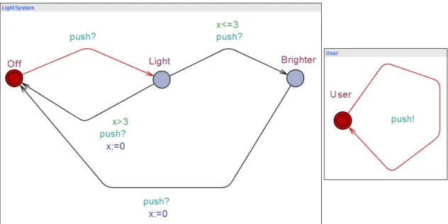
The UPPAAL window is made of three main parts: system editor, simulator and verifier. The system editor is used to construct models as a network of timed automata that can communicate with one another using the shared clock and variable values. Global and local declarations are made, together with system declarations which instantiate template objects and system processes. The simulator part of the UPPAAL window enables the simulation of possible executions of the system behavior. The verifier analyzes the system by checking its properties written in TCTL [35]. Figure4is an example of a system modeled in UPPAAL. It represents the light switch example, explained in the paper [40] by Behrmann et al. The global declarations of the system depicted in this example are shown in Figure5.
When the user first presses the button, the light is turned on. If he presses twice quickly, the light becomes brighter, but if he presses the button the second time after a longer time interval defined in the declarations and requirements, the light is turned off. In this example, the time interval has been set to three units of time. We have two timed automata in the model, called User and LightSystem. The User TA has one location, denoted by a vertex, called User and a loop transition that is annotated with the “push!” synchronization, which describes the behavior of the user pressing the light switch. Similarly, the LightSystem TA, which represent the differ-ent behaviors of the light bulb, has three locations called: Off (which is also the initial location, marked by double circles), Light and Brighter. The timing behavior of this model is controlled by one clock x. The logic behind the system model solution stands in the guards of the edges that connect these three locations. The transition from Off location to Light location occurs when the “push?” synchronization annotation of the edge takes place, meaning when a “push!” happens from the User TA. The automaton leaves the Light location to go to either Off or Brighter location, depending on which of the two edges’ guards is true, more specifically, on the clock value. One edge has been annotated with a guard of a clock value smaller or equal to three and a “push?” synchronization, whereas the other has been annotated with a guard of a clock value bigger than
Figure 4: The light system model in UPPAAL
Figure 5: Syntax declarations of the light system model in UPPAAL
three, a “push?” synchronization and an update on the clock value which resets it. The system transitions from Brighter to Off location through the edge annotated with a “push?” synchro-nization and an update of the clock value which resets it.
The semantics of this system, where transitions are labeled with numbers representing the delay amount in case of delay transition, whilst action labels are used in case of action transitions, would be as following:
(U ser, Off, x = 0)−−−−−−−−−−−−−−→ (U ser, Off, x = 1)delay f or 1−time unit (1)
delay f or 0.2−time units
−−−−−−−−−−−−−−−−→ (U ser, Off, x = 1.2)−−−→ (U ser, Light, x = 1.2)push (2)
delay f or 4−time units
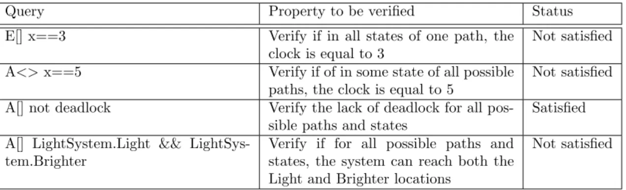
−−−−−−−−−−−−−−−→ (U ser, Light, x = 5.2)−−−→ (U ser, Off, x = 0)push (3) As we can see, the transitions can be either delays (of n units of time), or action transitions (push). Figure4is the simulator view of the UPPAAL window. We can notice that the loop transi-tion (annotated with only a “push!” synchronizatransi-tion) of the User TA and the first edge (annotated with only a “push?” synchronization) of the LightSystem TA are in red color as they represent syn-chronization channels in the simulation of the system model; their actions happen at the same time. In the verifier view of the UPPAAL window, we write queries in order to verify if the system meets certain properties. State operators are written as “<>” and “[ ]” [34] to indicate that the query refers to one state and all states respectively. Path quantifiers are notated as “A” and “E” to denote that the query should be satisfied by all paths and an individual path respectively. The “leads-to” operator, written as “- - >”, is used to show that when the notation on its left is sat-isfied, then eventually the notation on its right will be satisfied. The system is tested in different queries, which express true properties of the modeled system, and the verifier outputs text lines, which indicate whether or not the property is satisfied. Table1explains the queries, the properties
to be verified and the status of the different examples of property verifying queries.
Query Property to be verified Status
E[] x==3 Verify if in all states of one path, the clock is equal to 3
Not satisfied A<> x==5 Verify if of in some state of all possible
paths, the clock is equal to 5
Not satisfied A[] not deadlock Verify the lack of deadlock for all
pos-sible paths and states
Satisfied A[] LightSystem.Light &&
LightSys-tem.Brighter
Verify if for all possible paths and states, the system can reach both the Light and Brighter locations
Not satisfied
4
Research Method
In this section, we present the research methodology and development approach adopted in this thesis work, as presented in the work by Tayal [41] and Nunamaker et al. [42]. In order to achieve the goal of this thesis, the research methodology is comprised of a series of structured and systematic steps, which are problem-based and research-oriented. These steps are executed sequentially. If any problem arises during any of the steps, backtracking to the previous step is conducted. Figure6 is a graphical representation of the multi-step research method of this thesis work, described in Section4.1.
Figure 6: The methodology used in the thesis work
4.1
Research Method steps
In this subsection we represent a thorough description of the research method steps followed to complete the thesis work.
Formulate the preliminary research goals to be investigated. In this initial step, we formulated and proposed the following research goal: “A framework for the formal verification of EAST-ADL architectural models, extended with behavioral specifications in Simulink ”.
Literature review. A critical literature review of the current state-of-the-art in the topic in order to identify gaps in the research literature is performed. We investigate previous attempts of using both EAST-ADL and Simulink features in the modeling, simulation and formal verification of systems. The literature review is performed by splitting it in three pillars:
• Formal analysis of EAST-ADL models • Formal analysis of Simulink models
• Reflection on the approaches of EAST-ADL models with behavioral specifications in Simulink The review of literature consists of literature related to the formal verification of the respective models, their transformation to timed automata and tooling attempts to create formal models of EAST-ADL and Simulink models respectively. The research of the literature is performed in multidisciplinary citation databases, and publisher and scientific literature database like Scopus, SpringerLink, IEEE Xplore and Google Scholar. The key words used in the search queries to define and slenderize the search results are “formal analysis” or “formal verification” jointly with “EAST-ADL models” and/or “Simulink models”, combined in successive searches with “UPPAAL” and/or
“timed automata”. The results of this step are presented in Section2.
Refine thesis research goals from the previous step. After getting a better insight on the current state-of-the-art on the topic and making sure our research is not repeating previous works, we keep the initial research goal of proposing a framework, consisting of a tool that will take as input both EAST-ADL and Simulink models and generate automatically the network of timed automata to be verified with UPPAAL, based on the proposed transformation rules of the method. We refine the features of the tool like traceability to explicitly point to the original part it is checking, and reducing the number of hierarchy levels, based on previous attempts.
Propose transformation rules Starting from the initial step, a self education process with focus on the basic notations of EAST-ADL architectural language, Simulink tool and UPPAAL model checker, relevant to our work, takes place. These concepts are represented in Section3. We start with studying the notations of timed automata, used in the UPPAAL model checker. We look through its syntax and semantics and work with different examples, with the support of our supervisor, in order to get a better grasp of the model checking environment. We then move on to studying the Simulink notations and work with transforming different Simulink models (from simple, to more complex) to UPPAAL models, in order to start thinking on the transformation rules. Firstly, the transformation is done manually for each example, then we design the first drafts of the automatic transformation rules. After concluding this, we move on to studying the EAST-ADL architectural language notations. We start working with different models and then investigate how to transform simple EAST-ADL models into timed automata, in order to come up with transformation rules. Subsequently, we investigate EAST-ADL architectural models with Simulink behavioral specifications and their transformation to timed automata. We do a system-atic work on iteratively refining and improving the transformation rules and finalize them in a proposal, as explained more thoroughly in Section5.
Tool implementation The succeeding step is that of implementing the proposed transforma-tion rules in a tool that will automatically generate the formal model. Since two files would be needed to be read (EAST-ADL and Simulink), we decided to develop the tool by splitting it in six parts:
• Reading and parsing of the EAST-ADL file
• Implementation of the program methods that automate the transformation rules regarding the EAST-ADL features
• Reading and parsing of the Simulink file
• Implementation of the program methods that automate the transformation rules regarding the Simulink features
• Creating UPPAAL templates
• Implementation of the methods linking EAST-ADL and Simulink features
The development is conducted in incremental fashion, with iterations including testing the tool with modeling examples. A detailed explanation of the tool implementation takes place in Section6. Case study evaluation After finalizing the tool, we performed a case study on an industrial use case with the Brake-by-Wire (BBW) prototype, in order to evaluate our solution. BBW is the prototype of a braking system equipped with an Anti-lock Break System (ABS) function, which serves as an accurate model of a real industrial system. We use the BBW system in order to observe the use of the tool implementation and show the potential of our solution, by revealing the advantages and limitations. The application of our solution on the Brake-by-Wire use case is presented in Section7.
Result analysis As a final step, we analyze the results of the case study in terms of method applicability and scalability. The results are displayed in Section8whereas the discussion on their
analysis can be found in Section9. Final remarks are presented in Section10and Section11.
4.2
Threats to Validity
This subsection describes the validity threats which may limit the ability of our thesis work to yield reliable results or their scalability to more complex systems.
1. The method followed in order to achieve the goal of this thesis work does not include proof of the correctness of the transformation. We cannot validate that the formal model is in a bisimulation relation to the original model.
2. The validation is done only on one system, so other problems might appear when the formation is applied on other systems. Further studies would be needed to apply the trans-formation on other systems.
5
Transformation Rules
After providing the necessary theoretical background for conducting the thesis work, in this section we present the next step of our research study. Hereby, we propose the transformation rules required to create formal models of systems modeled in EAST-ADL architectural language, extended with behavioral specification in Simulink. Further on this section, we discuss the naming convention, how we cope with hierarchy and other important information, concluding with a set of examples to help the reader understand how the transformation rules produce the formal model.
5.1
Proposed Transformation Rules
Having conducted a thorough investigation of the transformation rules and logic that EAST-ADL (through the MetaEdit+ tool in our work) and Simulink use to model systems, we propose a set of transformation rules that transforms the EAST-ADL and Simulink model to a network of timed automata. We will use a simple example to illustrate the transformation, an example of a model without any kind of hierarchy and where the period and execution time are defined. The transfor-mation shall present how each element - which is relevant to our thesis work - of the EAST-ADL and Simulink model is mapped to an element or a set of elements in the timed automata. The resulting network of TA represent both the interface information encoded in the EAST-ADL ar-chitectural model and the behavior model represented by the associated Simulink model. The proposed transformation of the EAST-ADL and Simulink model to a network of TA is as follows. In order to preserve the informal semantics of the EAST-ADL architectural language, the pro-posed transformation produces a network of two synchronized TA for each EAST-ADL Function-Prototype: one TA for the interface, with the elements provided by the EAST-ADL architectural model, and one TA for the behavior (represented by Simulink), as presented in Figure7. They are named SystemInterfaceComponent TA and SystemBehaviorComponent TA, respectively. Compo-nent stands for the name of the FunctionPrototype, as specified in the EAST-ADL model. This naming convention is chosen in order to reflect traceability and will be applied to all the elements of the formal model which include the word “Component” in the respective annotation.
(a) SystemInterfaceComponent TA (b) SystemBehaviorComponent TA
Figure 7: A template of the network of TA produced by the transformation rules for a simple EAST-ADL model, with behavioral specifications in Simulink
The SystemInterfaceComponent TA, which is a template for all FunctionPrototypes without hierarchy in EAST-ADL, as depicted in Figure7a, serves as a representation of the interface of the current FunctionPrototype and is annotated according to it. It has two locations: the initial location, named Idle, which stands for the inactive state of the system, and the second location, named Compute, which stands for the active state of the system and triggers the SystemBehav-iorComponent TA.
The two locations are connected by two edges: i) an edge pointing from the Idle location to-wards the Compute location, which indicates that the system has left the initial location and thus, has started executing, and ii) an edge pointing on the opposite direction, which indicates that the system has left the Compute location, hence the execution is coming to an end. Constraints are applied on both locations (invariants) and on both edges (guards, updates or assignments, and synchronization channels) in order to make sure that the system behaves appropriately. These con-straints deal with features of the system like the time properties (period and/or execution time), communication between the TA and connections. We shall explain these elements before coming back to the constraints.
The timing properties of the FunctionPrototype, specified in the EAST-ADL architectural model, are mapped in the formal model through a clock named systemClockComponent, which is declared globally. This clock will keep track of the execution time and/or period of the current com-ponent, if they have been defined. The period and execution time are transformed to integer values. The synchronization between the SystemInterfaceComponent TA and SystemBehaviorCompo-nent TA is conducted through the synchronization channels startCompoSystemBehaviorCompo-nent and stopCompo-nent, where the former triggers the behavior of the system, whereas the latter signals the end of the behavior cycle of the whole system and sends the system back to the inactive state.
Each input and output port of the associated FunctionType, specified in the EAST-ADL ar-chitectural model, is transformed into a global variable. Their original naming convention of the respective port is preserved in the formal model in order to ensure traceability.
We can now look at the big picture of the SystemInterfaceComponent TA and explain how the constraints are applied on all the locations and edges, starting with the first edge which points from the Idle location towards the Compute location. An update is applied on this edge through a simple assignment, “systemClockComponent:=0 ”, in order to initialize the clock of the current component to zero, thus for it to start measuring the time as the execution has started. Moreover, a synchronization channel is annotated in this connection, “startComponent! ”, which signalizes the start of the behavior of the current component, triggering the execution of the SystemBehavior-Component TA. This location contains a guard as well, “systemClockSystemBehavior-Component==periodTime”, which is relevant after the first execution of the TA. This guard allows the formal model to check this TA again only after a full period cycle has been completed, ensuring the timing properties.
On the Compute location, we apply an invariant, “systemClockComponent<=execTime”, which allows the system to leave this location only after the execution time has finished. This is because we have now triggered the SystemBehaviorInterface TA and the execution time is the time this TA needs to execute the behavior of the component.
On the second edge, which points from the Compute location towards the Idle location, we apply a guard, an assignment and a synchronization as well. The synchronization channel, “stop-Component? ” listens to when the execution of the SystemBehaviorComponent TA has finished for the triggering to happen in order for the system to move on to this edge. An update happens on this edge and it is a simple assignment which passes the result of the SystemBehaviorComponent TA to the output edge of the component, using a temporary variable. The guard on this edge, “systemClockComponent==execTime” assures that only as much time as the execution time has passed.
After leaving the second edge, the system now goes back to the initial location, where an in-variant, “systemClockComponent<=periodTime”, defines that the system can leave this location only after a full period has been completed.
We will now explain the elements of the second TA. The SystemBehaviorComponent TA, as depicted in Figure 7b, represents the behavior of the current FunctionPrototype (specified in Simulink). It has two locations: the initial location, named Off, which represents the state that
the system does not perform anything, and the second location, named On, which represents the state of the system where it starts performing actions, thus, it ‘starts computing’.
These two locations are connected through two edges: i) an edge that points from the Off location towards the On location, which indicates that the execution of the component behavior has been triggered to start, and ii) an edge which points from the On location towards the Off location, which indicates that the execution of the behavior is already running and will soon finish. Constraints are applied on both edges of this TA. On the first edge, a synchronization channel, “startComponent? ” is listening to when the triggering of the execution of this TA will happen from the SystemInterfaceComponent TA. If triggered, the system will move on to the On location and from there to the second edge. This edge is composed of an update and a synchronization channel as described below.
As the behavior of the component is specified in Simulink, we transform the Simulink primi-tive blocks as C functions, where we update a temporary variable, “temp”, by assigning to it the result of the function on the second edge of the SystemBehaviorComponent TA. These functions are declared in the global declarations of the network of TA, together with the number of argu-ments and the type of the arguargu-ments (if any). They are global in order for them to be reused. In order to provide traceability and preserve the Simulink semantics, we name these functions by adjoining the ‘simulinkFunctionName’ to the string ‘Function(arguments)’, where arguments consists of the number and type of arguments (if any). If the component behavior has more than one Simulink block, then each connection between two Simulink blocks is transformed into sequential updates of the respective block functions on this edge, reusing the temporary vari-able. In that case, the update on the second edge would be “temp=simulinkNameFunction1(), temp=simulinkNameFunction2(temp)”.
After the update has been completed, the synchronization channel, “stopComponent! ” signal-izes to the system the end of the execution of the component behavior, which goes back to the initial Off location and leaves the SystemBehaviorComponent TA, going back to SystemInterface-Component TA.
In this example we deal with only one type of triggering: time-based triggering. However, there are two possible types of triggering:
1. Time-based triggering, which executes the FunctionPrototype at a specific time, where the timing specifications are made with periods;
2. Event-based triggering, which executes the FunctionPrototype in response to the occurrence of a certain event associated with it, where the timing specifications are made with a set of dedicated boolean variables, that need constant update and reset.
This information is gained from the associated FunctionType in the EAST-ADL architectural model. Moreover, the timing properties include the execution time, which can be either defined or not. In this example, we consider the scenario where the triggering is time-based, with the execution time specified. However, there are four combinations to be taken into consideration:
1. Time-based triggering with specified execution time (as the example we have just presented), 2. Time-based triggering without a specified execution time, where only the period-related
constrains remain and the Compute location is annotated as committed.
3. Event-based triggering with specified execution time, where only the execution-time-related constraints remain and we use a boolean variable for each component, named “variableCom-ponent ”, by updating and resetting it continuously (making it true or false) in order to trigger the event.
4. Event-based triggering without a specified execution time, where the only time-related con-straints are the ones related to the boolean variable.
5.2
Hierarchy
We now discuss how we the proposed transformation rules cope with hierarchy in EAST-ADL, Simulink or both. The presence of hierarchy affects the timed automata, by generating different models depending on the presence or lack of hierarchy. This subsection is divided in four parts which cover the possible combinations: EAST-ADL without hierarchy, EAST-ADL with hierarchy, Simulink without hierarchy, and Simulink with hierarchy.
5.2.1 EAST-ADL without hierarchy
In the case where the system is not hierarchical in EAST-ADL, the SystemInterfaceComponent TA would look like what we have already represented and discussed in Figure7a. This TA is annotated according to the the information that is extracted from the EAST-ADL model. Idle and Compute are the two locations, which represent the state where the system is not active and the state where the system starts executing, respectively. The first edge (pointing to the Compute location) triggers the execution of the SystemBehaviorComponent TA, whereas in the second edge (which points to the Idle location), the Outflow port(s) of the component is (are) assigned the result value of the SystemBehaviorComponent TA, upon its completion. The synchronization between these two TA is done by the synchronization channels startComponent and stopComponent. The information on triggering and execution time is mapped into the elements of this TA, acting as guards, invariants or updates throughout the execution of this TA.
5.2.2 EAST-ADL with hierarchy
We will now expand our transformation rules to the case of hierarchical EAST-ADL models, with behavioral specifications in Simulink. Let us consider as an example the model of a Function-Prototype with period and execution time defined. The FunctionFunction-Prototype is composed of two subsystems in EAST-ADL, which have behavioral specifications in Simulink. The SystemInter-faceComponent TA of the FunctionPrototype will be affected by this hierarchy. It will now be a template as the one represented in Figure8. This timed automaton will now act as a “coordina-tor” of the TA representing the interfaces of the EAST-ADL subsystems. For each EAST-ADL subsystems, a network of two TA will be generated, as explained above: SystemInterfaceSubsystem TA and SystemBehaviorSubsystem TA, where Subsystem stands for the name of the FunctionPro-totype of the respective subsystem. The execution order of the components is left to right, top to bottom as for the visual inspection of the EAST-ADL components.
Figure 8: A template of the network of SystemInterfaceComponent TA produced by the transfor-mation rules for a hierarchical EAST-ADL model, with behavioral specifications in Simulink
One location will be added to the SystemInterfaceComponent TA in Figure8 for each EAST-ADL subsystem it is comprised of, for a total of four locations in our example. They will be
connected by four sequential edges. The initial location remains the Idle location, and it again represents the inactive state of the system. On the first edge, pointing from Idle to the second location, the same constraints are applied: an update which initializes the systemClockComponent to 0 so it can start measuring time, a synchronization channel which triggers the SystemInterface-Subsystem TA of the first subsystem, and a guard which ensures that the formal model verifies this TA again only after a full period has been completed. The synchronization channel which syncs the SystemInterfaceComponent TA and SystemInterfaceSubsystem TA has a special annotation, where the keyword “Interface” has been added, in order to distinguish this synchronization channel from the one that is used to between the SystemInterface and SystemBehavior TA of the same component. The presence of hierarchy has affected this edge by adding another update, which reflects the mapping of the connection between the model and its subsystem. An update is added which assigns the Inflow port of the system to the Inflow port of the first subsystem.
On the second edge, which connects the second location with the third, two constraints are ap-plied. A synchronization channel which listens if the execution of the SystemInterfaceSubsystem1 TA has finished, and an update which assigns the result of the first subsystem to its Outflow port, through a temporary variable declared globally. The third edge, which connects the third location with the fourth location, has both an update and synchronization channel. The update reflects the connection between two EAST-ADL subsystems, which is mapped to the formal model as an assignment of the Output value of the first subsystem to the Input of the second subsystem.
The fourth location and the fourth edge are the same as in the case of no EAST-ADL hierarchy. On the last (fourth) location, an invariant is applied which makes sure for the system to go to the last edge only when as much time as the execution time of the whole system has passed. On the last location, which connects the fourth location to the initial location, a guard, updates and a synchronization channel are applied. The synchronization channel makes sure that the SystemInterfaceSubsystem2 TA has finished executing. The guard makes sure that only as much time as the execution time of this component has passed. As for the updates, they are assignments which represent the connection between the result of the behavior of the second subsystem to its Outflow port in the first update, and the connection between the subsystem and the system in the second one, represent by an assignment which passes the value of the Outflow port of the second subsystem to the Outflow port of the system. The initial location has an invariant that makes sure that the system leaves this TA only when a full period has passed.
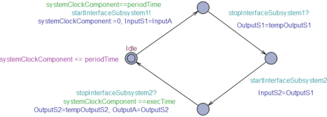
(a) The SystemInterfaceSubsystem TA of one of the subsystems
(b) The SystemBehaviorSubsystem TA of one of the subsystems
Figure 9: A template of the network of TA produced by the transformation rules for one of the subsystems which comprise an EAST-ADL model, with behavioral specifications in Simulink
The SystemInterfaceSubsystem, as depicted in Figure9a, is comprised of four locations in total - two more than the template used for the system without hierarchy in EAST-ADL. The four edges that connect the locations, are annotated only with synchronization channels. The pair of startIn-terfaceSubsystem1 and stopInterfaceSubsystem2 synchronization channel are used to communicate with the SystemInterfaceComponent TA, whereas the startSubystem1 and stopSubsystem1 are used
to communicate with the SystemBehaviorSubsystem1 TA, in order to trigger the behavior of the current component and signalize that the behavioral execution cycle has been concluded.
The SystemBehaviorSubsystem TA, depicted in Figure 9b, is similar to the TA representing the behavior of the system with no EAST-ADL hierarchy, shown in Figure7b. The same pair of TA as presented in Figure 9 would be applied for the second subsystem of which the system is comprised of. When the EAST-ADL model has hierarchy, the number of TA generated is twice the number of FunctionPrototypes present in the system, minus one - as in this case, there would be no SystemBehaviorComponent as the behavior of the system would be represented by the behavior of its subsystems, specifically SystemBehaviorSubsystem TA.
5.2.3 Simulink without hierarchy
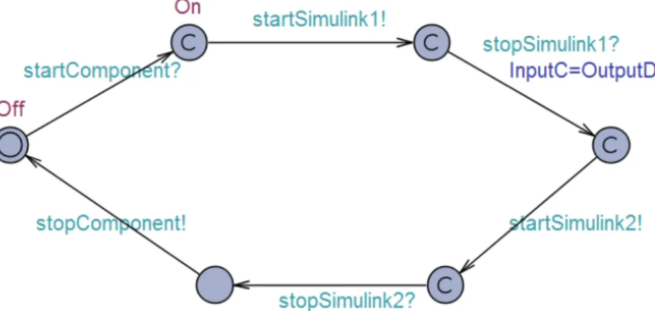
In the case where the system has behavioral specification in Simulink without any hierarchy, the SystemInterfaceComponent TA is a template which we have already introduced in Figure 7b. It consists of two locations: Off and On, which represent the states where the system does not perform anything and where it starts executing, respectively. This TA includes two edges connecting the locations in both directions and two synchronization channels - startComponent and stopComponent where Component stands for the name of the respective FunctionPrototype -, which serve to synchronize with the respective SystemInterfaceComponent TA. Simulink function blocks are represented with C functions on the last edge, where a local variable is used to save their outputs.
5.2.4 Simulink with hierarchy
Now we will expand the transformation rules explained above in an EAST-ADL component, with behavioral specifications in Simulink, where the latter is comprised of Simulink subsystems, thus manifesting Simulink model’s hierarchy. This would not affect the SystemInterfaceComponent TA none soever, thus we will not discuss this TA. The SystemBehaviorComponent TA would change from what we have represented in Figure7bto what is depicted in Figure10a. The SystemBehav-iorComponent TA of the current FunctionPrototype now acts as a “coordinator” of the network of TA representing the Simulink subsystems, as it is used to coordinate the triggering of each one of them and signalize the end of the execution cycle. The number of locations in this TA increased due to this. For each subsystem in Simulink, two locations are added. They represent the active and inactive state of the behavior of the subsystem. They are added after the On location of the SystemBehaviorComponent TA of the current FunctionPrototype. Each Simulink subsystem is represented in the formal model by a TA, as represented in Figure10band Figure10c. This TA is identical to the SystemBehaviorComponent TA of Figure7b, thus the same naming convention is used, aside from the fact that “Simulink” here represents the name of the Simulink subsystem. Synchronization channels are added in the edges to trigger the behavior of the respective TA of each Simulink subsystem, where the same naming convention is kept: startSimulink is used to trigger the start of the behavior, whereas stopSimulink is used to signalize the end of a behav-ioral cycle. ‘Simulink’ is annotated according to the name of the Simulink subsystems. When the execution order of the Simulink subsystems is sequential, the couples of locations of each Simulink subsystem are added one after another in the SystemBehaviorComponent TA of the current Func-tionPrototype. However, if the Simulink subsystems were to be executed in parallel, a broadcast channel would be used to trigger the behavior of both subsystems and only two locations would be added. Moreover, in this case, in the outgoing edge of the second added location, boolean vari-ables would be used to signal the ending of the execution of the behavioral cycle of both subsystems. The timing specifications remain in the SystemInterfaceComponent TA. The execution order of the components is left to right, top to bottom as for the visual inspection of the Simulink blocks. This is achieved by reading the information in the Simulink file that contain the order of execution of the BlockType(s).