UPTEC K15 035
Examensarbete 30 hp
September 2015
Optimisation of the bottom stirring
praxis in a LD-LBE converter
Investigations and tests on phosphorous
removal, nitrogen as stirring gas, and slopping
José Aguirre Castillo
Teknisk- naturvetenskaplig fakultet UTH-enheten Besöksadress: Ångströmlaboratoriet Lägerhyddsvägen 1 Hus 4, Plan 0 Postadress: Box 536 751 21 Uppsala Telefon: 018 – 471 30 03 Telefax: 018 – 471 30 00 Hemsida: http://www.teknat.uu.se/student
Abstract
Optimisation of the bottom stirring praxis in a LD-LBE
converter
José Aguirre Castillo
The LD-process, called after the cities Linz and Donawitz, is used to convert pig iron into crude steel by blowing oxygen on top of the pig iron. A LD-LBE converter, Lance Bubbling Equilibrium, also stirs the melt trough a bottom stirring system.
The bottom stirring in a LD-LBE converter is believed to have a positive effect alone on the phosphorous removal. Previous studies have shown that the temperature and slag composition are the main factors affecting phosphorus removal. Phosphorus binds to the slag easier at low temperature and to slag with certain levels of dissolved calcium (a process additive). Different praxes were tested and a better
dephosphorisation was reached. The bottom stirrings effect on the dissolution of calcium additives is a possible explanation to the results and mechanisms presented in this study.
The study also aimed to investigate the use of nitrogen as stirring gas instead of argon. Nitrogen is removed from the steel during the formation of carbon oxide gases. Nitrogen was used in varying amounts as stirring gas during the first half of the oxygen blow. It proved to be safe to use as long as there was a high content of carbon in the melt. However using nitrogen beyond half of the blow showed to be risky for nitrogen sensible steels; even in small amounts since there is not enough carbon left to degas the steel from nitrogen.
Slopping happens when formed gas from the LD-process is trapped in the slag. The slag level rises and sometimes it floods the converter resulting in yield losses. The influence of the bottom stirring on slopping was studied, which resulted in the conclusion that slopping cannot be avoided by simply improving the bottom stirring. Although some verification studies remains to be done, if the suggestions based on the results of this thesis were employed, savings in the oxygen and stirring gas economies could be made. Not least improvements on the iron yield.
ISSN: 1650-8297, UPTEC K15 035 Examinator: Erik Lewin
Ämnesgranskare: Annika Pohl Handledare: Charlotte Médioni
Populärvetenskaplig sammanfattning
En järnmalmsbaserad stålproduktion börjar med att järnmalm matas i en masugn tillsammans med koks, kalk och tillsatsämnen. Ut kommer råjärn med höga kol och svavelhalter. Råjärnet transporteras till stålverket i så kallade torpedvagnar. I vissa stålverk, t.ex. SSAB Special Steels i Oxelösund, renas råjärnet från svavel i torpedvagnen. I andra stålverk svavelrenar man i separata skänkar. Svavelreningen sker med bland annat kalciumkarbid som binder till svavlet.
Det svavelfattiga råjärnet måste sedan renas från kol för att bli stål. Det görs i en LD-konvertern (Linz Donawitz). LD-konvertern laddas med flytande råjärn som har en kolhalt på 4,5 procent och som är runt 1350 grader varmt. Råjärnet kyls genom att cirka 20 procent skrot tillsätts. En syrgaslans sänks sedan in i konvertern ovanför smältan och reningen startar. Syrgaslansen blåser syrgas i ultraljudsfart vilket oxiderar en del av järnet, så väl som kol, kisel, mangan, fosfor and andra föroreningsämnen i råjärnet. Kol försvinner ur konvertern i form av kolmonoxidgas. Andra oxiderade föroreningar och järnoxid bildar tillsammans en så kallad slagg som flyter ovanpå smältan. Det tillsätts även så kallade slaggbildare som förbättrar upptaget av föroreningar i slaggen. Processen varar i cirka 17 minuter och är mycket beroende av slaggen som bildas. Kol försvinner ur konvertern i form av kolmonoxidgas. Under processens gång rör man om smältan med hjälp av gaser som spolas genom botten av konvertern. Omröringen jämnar ut smältans sammansättning och temperatur. När man inte länge behöver avlägsna kol stoppas processen. Stålets temperatur är då cirka 1700 grader och kolhalten ligger nära 0,05 procent.
Stålet överförs sedan till en skänk för att skilja det ur slaggen. Stålet förädlas vidare i olika processer där sammansättningen justeras så att det möter kundens krav. Sedan gjuts stålet i strängar för transport till valsverk eller kunder.
Denna studie behandlar bottenomrörningen under LD-processen i SSAB Special Steels's stålverk i
Oxelösund. Omrörningen sker genom åtta porösa stenar i botten av konvertern som blåser med argon eller kväve. Gasflödet genom stenarna justeras genom ett ventilsystem. Under blåsningen rör man om med hjälp av förinställda program. Omrörningens primära funktion är att avlasta syrgaslansen. I fallen där ingen bottenomrörning finns måste syrgaslansen blåsa ”hårdare” på stålet för att avlägsna kol. Avlastningen som bottenomrörningen bidrar med gör att processen även kallas för LD-LBE, där LBE står för Lans Bubbling Equilibrium.
Bottenomrörningen tros ha en positiv effekt på stålets rening från fosfor. Sedan tidigare vet man att
temperatur och slaggsammansättning är de största faktorerna som påverkar fosforreningen. Fosfor tas lättare upp i slaggen vid låga temperaturen samt i slagg med högre kalkhalter. Olika omrörningsprogram testades och en bättre fosforrening nåddes. Bottenomrörningen visade sig ha positiva effekter som är teoretisk kopplade till kalksmältning. Två möjliga förklaringsmekanismer hittades.
Studien undersökte även användningen av kväve som omrörningsgas istället för argon, då kväve är ekonomisk fördelaktig gentemot argon. Kväve finns inlöst i råjärnet som sätts in i konvertern. Kvävgasen försvinner ur stålet under och med hjälp av kolreningen. Det visade sig vara säkert att använda kväve från start fram till halva syrgasblåset på kvävekänsliga stålsorter, var efter man sedan byte till argon. Kväve som används sent under blåset visade ge högre kvävehalter.
Urkok är en kraftig volymökning av slaggen som sker när bildad gas från reningen av smältan fångas i slaggen och får slaggen att ”koka över”. Urkok resulterar i ekonomiska förluster då slaggen som lämnar konvertern vid urkok är rik på järn. Bottenomrörningens eventuella påverkan på urkok studerades. Det visade sig att urkok inte kan undvikas genom att enbart optimera bottenomrörningen.
4
Contents
1 Introduction ... 5
1.1 Background... 5
1.2 Aim and scope ... 6
2 Process description ... 6
2.1 The chemistry of the process ... 7
2.1.1 The first blow period ... 7
2.1.2 The second blow period ... 8
2.1.3 The third blow period ... 9
2.2 The bottom stirring system ... 10
2.2.1 Stirring programs ... 11
2.2.2 Limitations ... 12
3 Theory... 13
3.1 Previous work ... 13
3.2 The dephosphorisation process ... 13
3.2.1 The formation of dicalcium silicates (phosphorous carriers) ... 14
3.3 Nitrogen in LD ... 15
3.4 Slopping ... 16
4 Method of work ... 17
4.1 Test programs ... 17
4.2 The bottom stirring condition ... 18
4.3 Sampling ... 18
5 Results and discussion ... 19
5.1 General results ... 19 5.3 Dephosphorisation results ... 22 5.4 Nitrogen results ... 24 5.5 Slopping control ... 25 6 Conclusions ... 26 6.1 Recommendations ... 27 7 Further work ... 27 8 Acknowledgments ... 27 9 References ... 27 10 Appendix ... 29 10.1 Test programs ... 29
5
1 Introduction
1.1 Background
Steel is an alloy of mainly iron and carbon. The content of carbon is below 2 Wt-% for high alloyed steels. As any other alloy, the composition of the steel plays an important role on its properties.
SSAB is a company known worldwide for its wide range of high strength steel. Domex®, Hardox® and Armox® are some of the brands of high strength steel that SSABs produces. High strength steels are
produced with low contents of alloying elements compared to stainless steels. A lot of effort is put in having right the contents of e.g. carbon, manganese, phosphorous, sulphur and silicon.
SSAB Special Steels in Oxelösund has an ore-based steel production. The steel production process chain in Oxelösund is represented in Figure 1.
Figure 1. The steel production process in Oxelösund[1] (edited).
The coking plant produces coke, which is later used as fuel and reducing agent in the blast furnace. There are two blast furnaces in Oxelösund. They are mainly charged with coke and iron ore pellets. the iron ore is reduced and melted to pig iron, which is tapped in torpedo cars. The torpedo cars transport the pig iron to the steel plant. In Oxelösund, calcium carbide is injected to the pig iron in the torpedo cars in order to remove sulphur. Sulphur together with calcium forms a slag on top of the pig iron. The slag is removed after the pig iron is poured into a transport ladle before been charged to the LD-LBE (Linz Donawitz-Lance Bubbling Equilibrium converter.
The LD-LBE converter is charged with pig iron, scrap and slag forming agents. Carbon and other impurities are reduced by blowing oxygen at supersonic speed on top of the pig iron. The impurities and slag forming
Post-treatment of molten steel LD-LBE converter
Torpedo cars Blast furnaces
Coking plant Continuous casting
Slab furnaces
Four-high rolling mill
Quenching and tempering Customer delivery
6
agents forms a basic slag. The main product from the LD-LBE converter is crude steel which is immediately alloyed while it’s been tapped to a ladle. The crude steel undergoes a Tyssen-Niederhein (TN) treatment. At the TN-station, reducing agents are added and the melt is stirred by using argon gas for thermal and chemical homogenization. After the TN treatment, the crude steel either goes to a vacuum tank degasser station (VTD) or a ladle furnace station (LF). In either VTD- or SU-station, more alloying elements and oxidizing agents are added, and the melt is heated with graphite electrodes. At the LF-station the melt is stirred by induction and/or argon bottom stirring, while the VTD-station is equipped only with argon bottom stirring. The main difference of the two stations is that the VTD-station is used to depressurize the melt, which minimizes the contents of unwanted gas elements in the steel. The finished steel melt is then sent to a continuous casting station for solidification. The steel is then finished to be sent to the customer or to the milling plant at Oxelösund or shipped by train to another milling plant in Borlänge.
1.2 Aim and scope
This master thesis aims for the improvement of the bottom stirring in the LD-LBE converter in Oxelösund, during the oxygen blow by adjustment of the settings (stirring praxis). The main objectives are:
Optimisation of the bottom stirring flow rates during the oxygen blow. The improvements aim toward an optimal dephosphorisation of the steel.
Investigations on the use of nitrogen as bottom stirring gas during the blow and nitrogen absorption of the steel.
Minor investigation on the effect of bottom stirring on slopping.
A previous bachelor thesis with the post-stirring after finished oxygen blow at SSAB Oxelösund has shown that it improves the removal of some impurities [2]. Therefore this thesis will not treat the post-stirring.
2 Process description
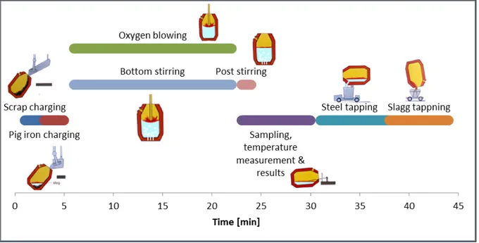
The following description is specific for the steelmaking process in Oxelösund unless anything else is stated. A LD-LBEs main function is to reduce the content of carbon in the pig iron coming from the blast furnace. The LD-LBE process is a procedure that runs for about 45 minutes; also called the “tap to tap” time. The procedure is illustrated in Figure 2 and it runs as follows:
Scrap is charged. Pig iron is charged.
The converter is straightened up.
A lance which blows oxygen at supersonic speed is lowered in to the converter right above the melt. The oxygen blow starts. The bottom stirring starts as well and it runs as it is programmed to do. Slag
forming agents are added during the first minutes.
The blow ends. The pig iron is now converted into crude steel. The steel is then stirred with inert gas in order to homogenize the melt. Steel samples and temperature are taken.
Additional blowing and/or bottom stirring may be used if the sample analysis did not match the desired composition.
Tapping of the steel. Alloying elements are added while tapping. Tapping of the slag.
SSAB Oxelösund has a converter with the maximum capacity of 225 t crude steel, which corresponds to about 1/5 of the converters volume[3]. The other 4/5 of the volume is needed for the decarburization process and slag foaming, see Figure 3.
7
Figure 2. The LD procedure.
2.1 The chemistry of the process
The oxygen blow is often divided into three periods, which coincide with the slag formation. The first period lasts for 4-5 minutes, and is called the slag forming period. The second period is where most of the
decarburization happens and it lasts for 10-11 minutes. The third period is the final stage of the blow, it is a critical period for the yield loses of iron and it lasts for 2-3 minutes [4].
2.1.1 The first blow period
The converter is charged with about 160 ton pig iron and 45 ton scrap. Shortly after the blow starts, the converter is also charged with burnt lime (CaO) and dolomite lime (CaO and MgO).
The oxygen lance is lowered on top of the melt at a height controlled by a lance program. The lance is at a high position at the beginning of the blow. When the oxygen strikes the pig iron at supersonic speed (Mach 2,7[3]), it creates a crater which becomes a reaction zone (also called the hot spot), see Figure 3. The main combustion reaction at the crater is the oxidation reaction of iron, which is followed by the oxidation of silicon and manganese. A reaction index explanation is shown in Table 1.
{Fe} + ½ O2 (g) → (FeO) [Si] + O2 (g) → (SiO2) [Mn] + ½ O2 (g) → (MnO) (1) (2) (3)
The products of these reactions join the slag. FeO and MnO acts as a flux aids which help to dissolve the added CaO. The dissolution of CaO can also be improved by adding additional flux aids and the use of bottom stirring. At the end of the first period, 30-40 % of the added CaO has dissolved and started forming slag[4]. Infusible dicalcium silicates begin to form in the slag. At this point the composition of the slag has gone from point 1 to point 2 in Figure 4.
Table 1. Chemical reaction index explanation.
Index Explanation
[X] Specie X in the molten metal phase
(Y) Specie Y in the slag phase
{Z} Specie Z in the metallic bulk phase (iron)
8
Figure 3. Reactions zones in a LD-converter[4].
Figure 4. LD-slag composition[4] (edited).
2.1.2 The second blow period
At this point, most of the silicon is gone. See Figure 5. The lance is lowered. The temperature of the melt rises and the decarburization process starts along with the oxidation of phosphorous.
[C] + ½ O2 (g) → CO (g)
2[P] + 5/2 O2 (g) → (P2O5)
(4) (5)
Carbon exits the converter as CO gas. CO gas among other emissions is taken care of to protect the
environment. Almost all CO is burned to CO2[4].
CO (g) + ½ O2 (g) → CO2 (g) (6)
As the oxygen jet strikes the melt, droplets are thrown up in the slag. The droplets which contain carbon and other dissolved elements help reduce the FeO in the slag. The contact surface between the droplets and the slag becomes the second reaction zone, see Figure 3. There the following reactions take place:
(FeO) + [C] (in the droplet) → {Fe} + CO (g)
2(FeO) + [Si] → 2{Fe} + (SiO2)
(FeO) + [Mn] → {Fe} + (MnO)
5(FeO) + 2[P] → 5{Fe} + (P2O5)
(7) (8) (9) (10)
9
At this point, the concentration of FeO in the slag decreases. The slag composition goes from point 2 to 3 in Figure 4.
The bottom stirring during the second blow period improves the mass transport of the third reaction zones in Figure 3. The third reaction zone is located in the melt, and it is driven by different oxygen sources. Some of the oxygen sources are:
Dissolved oxygen from the oxygen jet.
FeO and other oxides inside metal droplets falling through the slag and back into the melt. Slag that is pushed into the melt by the oxygen jet.
Dissolved oxygen at the interface between the slag and the iron melt.
Figure 5. Composition variations of melt[4].
2.1.3 The third blow period
In the third blow period the decarburization process decreases as the carbon concentration in the melt decreases. A good mass transport at this point is needed, thus many bottom stirring programs ends with maximum flow[5][6][7][8].
The content of FeO in the slag rises as the decarburization decreases. See Figure 6. The increased formation of FeO rises the temperature which dissolves more CaO. The composition of the slag finally reaches point 4 in Figure 4. Additional blowing ends up increasing the content of FeO in the slag and the composition reaches point 5.
10
Figure 6. Composition variations of slag[4].
2.2 The bottom stirring system
Some of the advantages of the LD-LBE process compared to other processes found in literature are [4]: Lower oxygen content in the steel.
Higher Manganese content in the steel. Less lining wear.
Better mass and heat transport in the melt.
The LD-LBE converter body is made of steel with a ceramic lining (magnesite of different qualities,
MgCO3). The stirring plugs are made of fused magnesia (very high MgO content), which can withstand the
high temperatures of the process. The LD-LBE converter in Oxelösund has 8 stirring plugs, which are represented as dark dots at the bottom of the converter in Figure 7, and in Figure 8. Each plug has an individually applied flow. The used gas, volume and flow are controlled by the stirring programs in the LD process computer. The bypass is always used when no flow is applied to the plugs by the stirring programs; it consists of a constant counter pressure, which prevents steel from getting into the plugs and cause
clogging. The stirring plugs can also be turned off individually, in which case they are applied a counter pressure. The previous thesis with the bottom stirring in Oxelösund was performed using only every other stirring plug[2]. In this thesis, all stirring plugs were used.
11
Figure 7. Representation of the LD-LBE converter in Oxelösund [9] (edited).
Figure 8. Picture of the converter bottom in Oxelösund (27 mars 2015).
2.2.1 Stirring programs
The bottom stirring parameters are controlled by the oxygen fraction left to blow. Table 2 shows the
reference program for this study. A program row tells the oxygen fraction, chosen gas and its flow. The next row shows the next fraction, a gas type and a flow. Stirring programs can have up to 10 rows.
Table 2. Reference bottom stirring program.
Row Oxygen fraction left, [%] Gas type Flow, [m3/h]
1 100 Argon 250
2 75 Argon Bypass
12
The stirring programs can be abolished during the blow using a manual function called “turbo stirring”. The turbo flushes a certain amount of gas with a high flow (≈350 m3/h). The turbo stirring is used in different occasions such as:
To prevent slopping.
To improve the melting of slag forming agents. To open clogged stirring plugs.
2.2.2 Limitations
The bottom stirring is very dependent of the stirring plugs condition. Researchers at Ruukki’s steel factory in Raahe, Finland, conducted an extensive work in order to address the wear mechanism of their LD-LBE converter and to improve their bottom stirring [10]. The study showed that some of the wear mechanisms that affect the converters lining as well as the stirring plugs are:
Mechanical wear due to impact, erosion and stresses. Chemical wear due to corrosion, oxidation and reduction. Thermo chemical wear caused by thermal shocks.
Another difficulty with the bottom stirring is the clogging of the stirring plugs. This happens when a layer of slag is built over the plugs, see Figure 9. A common cause of clogging is an improperly done converter slagging. Converter slagging is a converter lining protection by slagging. A bit of slag is left in the converter after tapping most of it. The LD-operators tilt the converter forwards and backwards in order to cover and protect the lining with slag. A way to prevent clogging is by having low concentrations of MgO (less dolomite lime), thus the slag layer is easily worn out when new slag (non MgO saturated) slag is formed.
13
3 Theory
Theory and previous works of concerns in presented in this chapter.
3.1 Previous work
The impact of different bottom injection equipment in LD-LBE converters has been studied[11]. It was stated that stirring plugs and nozzles produce similar mixing effects in the bath, in concerns of homogeneity and mixing time. However, the turbulence produced and volume-delivery depend on the outlet design and number of tubes inside the stirring plugs, respectively[7][12][13].
The kinetic energy applied to the melt depends on many factors. Koria and Lang [14] studied the bottom stirrings effects on scrap melting in BOF with laboratory models and concluded that the applied kinetic energy depends on the gas flow rate, melt bath height/diameter ratio and amount of scrap. The kinetic energy has also been studied in terms of decreased mixing time. It was found that a deep bath with or without scrap mixes easier than a shallow bath at all flow rates.
Further, a study has found that the size of the purging plugs affects the gas delivery capacity [10]. Larger stirring plugs can deliver higher flows; the down side is that more gas is needed.
It has also been shown that using bottom stirring raises the bath level by pushing it up [14][15][16].
3.2 The dephosphorisation process
Equation(5) and (10) in section 2.1.2 shows the dephosphorisation reactions in terms of molecules, while it can also be seen in terms of ions.
Also simplified as (net reaction):
In that way the equilibrium can be seen as:
Where Kp is the equilibrium constant and ai are the ion activities. Species with higher activities have more energy to leave their current phase, and the opposite for low activities. A phosphorous partition between slag and melt can be drawn from equation (14):
Where fP is the activity coefficient of phosphorous; and CP is the capacity of phosphorous in the slag. The capacity of phosphorous can also be described as:
Equation 14 and 15 indicates that the partition of phosphorous between the slag and the melt depends on the following factors:
14
High activity of O2 in the slag and the melt. Higher O2 activities in the slag are achieved with higher contents of basic oxides in the slag phase. The more basic oxide contents the more the slag gets ionized, which is favourable for ions such as SiO44- and PO43-. The higher O2 activity in melt
oxidizes more phosphorous. Unfortunately, this also depends on the contents of other elements in the melt with higher oxygen affinity than phosphorous, e.g. C, Si, Mn and Al.
Basic oxide:
Acidic Oxide:
Lower activity of PO43- in the slag and higher activity of PO43- in the melt. This lowers the chance of phosphorous reversal from the slag to the melt. The activity is kept low with high contents of basic oxides, because of the attraction between metal cations and phosphate ions.
The temperature.
Equation (19) is also called Healy’s correlation[17]. The equation was conceived after experiments with constant slag compositions and varying temperatures. The equation shows that the phosphorous removal is enhanced by lower temperatures.
However, there is a limit of basicity for the removal of phosphorous. Too high contents of CaO in the slag phase increases the viscosity which lower the transport of phosphorous in and into the slag.
The first period of the blow is critical for the removal of phosphorous. Dicalcium silicates created in this period are good phosphorous carriers [18]. Dicalcium silicates are infusible, meaning that they have high melting temperatures. Phosphorous containing dicalcium silicates stay as crystals during the first and second period of the blow. At the end of the second period, the reduction reactions of FeO increase the temperature of the slag. The crystals melt and phosphorous is released; thus the phosphorous hump in Figure 5, at about 80 % of blow time.
Previous work with the post stirring in Oxelösund has shown that additional post stirring after the oxygen
blow with increased gas flow rates (Nm3/h) and increased gas volume (m3) improve the removal of
phosphorous among other elements, (most likely) due to the cooling effect and mass transport provided by the bottom gas injected[2].
It is also known that higher amount of FeO in the slag improves reaction (10)[17][18]. 3.2.1 The formation of dicalcium silicates (phosphorous carriers)
Dicalcium silicates are formed after the addition of lime and dolomite. The reactions are shown below. Dicalcium silicates from lime (CaO):
Dicalcium silicates from dolomite (CaO∙MgO):
The reaction rates of (20) and (21) depend partly of the contents of FeO and SiO2 before the additions of lime
15
particles are more likely to be penetrated by iron silicate phases (2FeO∙SiO2), resulting in a faster dissolution. Less porous lime or burnt lime (used in Oxelösund) dissolves slower than porous lime, not only because of the lower porosity, but because of built up layers of dicalcium silicates around the burnt lime particles. Thus burnt lime dissolves at lower rates.
3.3 Nitrogen in LD
The pig iron charged in to the LD-LBE converter has a nitrogen content of about 60 ppm[19]. Nitrogen is also found in the atmosphere (about 78%), and as bottom stirring gas in the LD-LBE converter.
Nitrogen is used as a bottom stirring gas when the converter is uncharged to prevent plug clogging and to save on Argon costs. Nitrogen may also be used during the blow, depending of the type of steel (e.g. nitrogen alloyed steels).
A thesis work performed at SSAB Europe steel plant in Luleå charted the whole nitrogen
absorption/desorption course in the LD-LBE process[19]. Several samples were taken in different steps of the LD-process during the thesis work in Luleå. Pig iron samples taken from a charged converter before the blow showed that the atmospheric exposure during the charging raised the nitrogen contents in the pig iron with about 5 ppm. It was found that Nitrogen’s transition from gas to melt occurred in the following steps, also seen in Figure 10:
Transport within the gas phase by diffusion. Gas-melt interface reaction.
Transport within the melt by diffusion.
Figure 10. Nitrogen’s transition between a gas phase and a melt[19] (edited).
When the blow starts, generated CO gas in the melt helps the transport of nitrogen to the surface. Oxygen from the jet and generated CO gas lowers the nitrogen partial pressure in the atmosphere inside the
converter. The effect of both transport and low nitrogen partial pressure enhances the nitrogen desorption. As the decarburization rate decreases, the nitrogen desorption decreases as well. At the end of the blow, the increasing O2 activity at the melt-slag interface interferes with the reaction of nitrogen at the interface. Thus insignificant nitrogen amounts are absorbed and/or desorbed at the end of the blow. See Figure 11.
16
Figure 11. Nitrogen’s desorption rate in an oxygen converter[19].
3.4 Slopping
As explained in section 2.1.2, the oxygen jet throws droplets from the melt up into the slag. The produced CO gas by the reduction of FeO in the slag is then trapped in the slag. The liquid slag becomes foamy which increases the slag's height. In different occasions, the growth of the slag becomes excessive and results in the slag flowing out of the converter vessel through the top. This phenomenon is called slopping. Slopping is unwanted due to yield losses when FeO rich slag leaves the converter, environmental issues and security reasons.
The excessive slag growth was studied and charted during a licentiate thesis performed at SSABs steel plant in Luleå [5]. The four most common causes of slopping were found to be:
1. Increased slag viscosity. A higher slag viscosity increases the residence time of the metal droplets in the slag. Thus more droplets are simultaneously used to produce CO inside the slag, resulting in slopping. Common causes of an increased slag viscosity are [5]:Unfitting pig iron and scrap composition; Additions of FeSi; Temperature drops after additions; The use of burnt lime which is harder to melt.
2. High FeO contents in the slag which speeds up the production of CO inside the slag. The slag becomes over-oxidized, see Figure 12. Common causes [5]:Soft blowing, due to improper (often too high) lance position or lance wear; Addition containing iron (e.g. FeSi) or FeO (e.g. pellets).
3. Increased decarburization rate which increases the production of CO gas. 4. Reduced converter volume. Causes: Build-up slag layers; Over-charging.
17
Figure 12. Illustration of the connection between the oxidizing state of the slag and the sloping probability[5].
4 Method of work
This study was performed in close contact with researchers, developers and technicians specialized in the LD-LBE station. Results and statistic data of the reference program was studied. A total of 14 test programs were investigated.
4.1 Test programs
The test programs (TP) are represented in Table 3. They are also presented graphically in the appendix.
Table 3. The test programs. Flows in m3/h. The use of argon is marked in a pink colour, while nitrogen is marked in blue.
Test programs
REF TP1 TP2 TP3 TP4
O2 fraction Gas Type Flow Gas Type Flow Gas Type Flow Gas Type Flow Gas Type Flow
100 Ar 250 N2 250 N2 330 N2 330 N2 330 85 Ar 25 N2 0 N2 0 N2 250 N2 250 75 Ar 0 N2 0 Ar 0 N2 250 N2 250 60 Ar 0 N2 0 Ar 0 N2 250 Ar 200 50 Ar 0 N2 0 Ar 0 Ar 0 Ar 200 25 Ar 330 N2 0 Ar 0 Ar 0 Ar 200 20 Ar 330 N2 0 Ar 0 Ar 330 Ar 200 15 Ar 330 Ar 330 Ar 330 Ar 330 Ar 330 10 Ar 330 Ar 330 Ar 330 Ar 330 Ar 330 TP5 TP6 TP7 TP8 TP9
O2 fraction Gas Type Flow Gas Type Flow Gas Type Flow Gas Type Flow Gas Type Flow
100 Ar 0 N2 250 N2 330 N2 0 N2 330 85 Ar 0 N2 250 N2 330 N2 0 N2 300 75 Ar 0 N2 250 N2 330 N2 330 N2 250 60 Ar 0 N2 250 N2 330 N2 300 N2 230 50 Ar 0 Ar 250 Ar 330 Ar 330 N2 300 25 Ar 0 Ar 250 Ar 330 Ar 0 N2 230 20 Ar 0 Ar 250 Ar 330 Ar 0 N2 200 15 Ar 330 Ar 250 Ar 330 Ar 0 N2 250 10 Ar 330 Ar 250 Ar 330 Ar 0 N2 330
18
TP 1, 2, 3 and 4 are modified versions of the reference program. The purpose of TP 1 and 2 was to try shorter stirring times while TP 3 and 4 tried extended stirring. TP 5 is a modified version of an old test program which resulted in slopping at the end of the blow. The purpose of TP 5 was to try a delayed start of the bottom stirring at the end of the blow. TP 6 and 7 were made to try continuous stirring at different rates. TP 8 was made as a theoretically “wrong” program. The purpose of it was to try the dependence of bottom stirring at the end of the blow and an increased mass transport during the main part of the decarburization. TP9 was made to follow the lance program with the exception of the slightly harder stirring at the middle of the blow.
The stirring programs were tested during different time periods to allow all LD-operator teams to use them. The tests began 1 week after the converter had got new lining and stirring plugs, meaning that the conditions of the converter and the bottom stirring were optimal. The tests went on during an entire lining lifetime (about 8 weeks).
Based on the test results from the first 9 programs and observations on slopping, three of them were
modified. The modified programs are shown in Table 4 along with TPX and TPX2, which were attempts of combining the results of TP1 and TP4. These were tested 1 week after another lining and plug change. They are also presented graphically in the appendix.
Table 4. Modified test programs. The use of argon is marked in a pink colour, while nitrogen is marked in blue.
Additional programs
MTP2 MTP3 MTP4 TPX TPX2
O2 fraction Gas Type Flow Gas Type Flow Gas Type Flow Gas Type Flow Gas Type Flow
100 N2 330 N2 330 N2 330 Ar 250 Ar 250 85 N2 330 N2 250 N2 250 Ar 0 Ar 0 75 Ar 0 N2 250 N2 250 Ar 300 Ar 0 60 Ar 0 N2 0 Ar 200 Ar 250 Ar 250 50 Ar 0 Ar 0 Ar 200 Ar 250 Ar 250 25 Ar 0 Ar 0 Ar 200 Ar 250 Ar 250 20 Ar 0 Ar 330 Ar 330 Ar 330 Ar 330 15 Ar 330 Ar 330 Ar 330 Ar 330 Ar 330 10 Ar 330 Ar 330 Ar 330 Ar 330 Ar 330
4.2 The bottom stirring condition
Continuous documentations of the purging plugs condition and other aspects of concern at the LD-LBE station were carried out. The documentations consisted of several interviews with the different LD-operator teams, as well as weekly pictures of the converters bottom.
4.3 Sampling
Nitrogen was used in most programs as seen in Table 3 and Table 4. The use of more nitrogen in the process is economic advantageous, and the experiments investigated if there were any risk of getting unwanted higher nitrogen contents in the crude steel. As a precaution and in order to keep track of the nitrogen
contents, additional steel samples were taken after the blow for each test program. Ordinary steel samples are analysed with OES (optical emission spectrometry), while the additional samples taken were analysed with LECO®, which is an instrument for MDGCMS (multi-dimensional gas chromatograph mass spectrometry). The LECO® analysis gives a more accurate reading of the nitrogen contents in the steel, compared to OES. The samples were manually taken by LD-operators, and were analysed by the laboratory in the SSAB Oxelösund site.
19
5 Results and discussion
The results of this work are presented below.
5.1 General results
Section 2.2.2 summarizes the limitations of the bottom stirring. No damages were noticed on the stirring plugs during the tests. However, each test program (including REF) was used during clogging of the stirring plugs. In some cases, the stirring practice was the cause of clogging.
Table 5 presents the number of observations per test program. One observation correspond to one heat. Figure 13 represents the percentage of result coming from clogged stirring plugs. Clogging was defined as 3 or less visible stirring plugs.
Table 5. Number of observations per program.
Program Number of observations
REF 192 TP1 103 TP2 106 TP3 232 TP4 179 TP5 116 TP6 133 TP7 116 TP8 76 TP9 73
As seen in Figure 13, programs with high or constant flows were better for avoiding clogging. Programs with low flows e.g. TP5 caused clogging more often. Although the clogging percentage appears to be related to the stirring praxis of each program, additions in the LD-process and the human factors play a big role, see section 2.2.2.
The effects of clogging were noticed on the carbon contents in the crude steel. Figure 14 shows an interval plot of mean values and 95 % confidence intervals for both clogged and unclogged results. It can be seen that clogging does results in less effective decarburization, but at a non significant level according to the
confidence intervals from clogged and unclogged results presented in Figure 14.
0% 10% 20% 30% 40% 50% 60% REF TP1 TP2 TP3 TP4 TP5 TP6 TP7 TP8 TP9 Per ce n t cl o gg in g
20
Figure 14. Interval plot of the carbon OES analysis from each stirring program. REF=Reference program, TP=Test Program, C=clogged.
The additional test programs had all higher flows and no major clogging was noticed. Each of them scored about 20 % clogging. The numbers of observations from those programs are shown in Table 6.
Table 6. Number of observations per program.
Program Number of observations
MTP2 163
MTP3 94
MTP4 127
TPX 120
TPX2 128
The results in decarburization for all programs are shown in Figure 15. Results from both clogged and unclogged conditions are shown. Some of the tested programs showed to be better than the reference. TP4, MTP4, TPX1 and TPX2 are programs of similar praxis. They have a continuous flow during the major part of the decarburization process. They later stir the melt with a high flow which provides with good
homogeneity, which thereof enhances the contact and reaction of carbon with oxygen at the end of the blow, as previously shown in Table 4.
TP 9-C TP9 TP 8-C TP8 TP 7-C TP7 TP 6-C TP6 TP 5-C TP5 TP 4-C TP4 TP 3-C TP3 TP 2-C TP2 TP1 -C TP1 RE F-C REF 0,08 0,07 0,06 0,05 0,04 Ca rb on in c ru de s te el [% ]
95% CI for the Mean
21
Figure 15. Interval plot of the carbon OES analysis from all programs.
The results in Figure 15 do not prove that the programs with carbon contents below the contents of the reference are better. The final results of carbon depend mostly on the oxygen blown and the LD-operator controlling the process rather than the effect of bottom stirring. A LD-operator can prolong the oxygen blow
in order to oxidize more carbon. He can also increase the flow of blown O2, which gives the same kinetic
effect as bottom stirring but is bad for the O2 gas economy. Figure 16 and Figure 17 presents the blowing
time for each program and the total amount of O2 gas used. Lowering the lance position gives a similar effect
as increasing the O2 flow, but the lance position is not logged (when altered), therefore it cannot be studied.
Figure 16. Interval plot of the oxygen blow duration time per program
Figure 17. Interval plot of the oxygen amount used per program
According to Figure 15, Figure 16 and Figure 17, TP2 and MTP4 are the ones with coherent results in all three plots. Those programs showed good decarburization results together with short blowing time and a
good O2 economy. Both programs have very similar praxis at the beginning and the end of the oxygen blow,
but not in the middle. The similarity of the results of these programs cannot be explained without further work, see section 7.
22
5.3 Dephosphorisation results
As explained before, the removal of phosphorous is very dependent on the slag's composition and process temperature. It is very difficult to tell the effects of a stirring praxis by only looking at the crude steel analysis, see Figure 18. All values have been divided by the mean of the reference program, due to company interests, see equation 22. The results include both clogged and unclogged results.
Figure 19 represents an interval plot for the relative phosphorous difference of all programs, also following equation 22.
Figure 18. Interval plot of the phosphorus OES analysis from all programs.
Figure 19. Interval plot of the relative phosphorus difference between the OES analysis of pig iron and crude steel from all programs. The blue arrows mark test programs following the presented mechanism 1, red arrows mark test programs following mechanism 2.
23
A higher relative difference tells there are larger differences in the phosphorous analysis before and after the blow. Figure 19 show that TP1 and TP5 are above and do not overlap with the results of the reference program. The mean values of MTP3, TP4, MTP4 and TP8 are also above the confidence interval of REF. There are two possible dephosphorisation mechanisms following the literature in chapter 3.2 regarding the beginning of the blow that could explain these results.
Mechanism 1: bypass or low flows at the beginning of the blow allows the production of more FeO before the additions of lime and dolomite lime. This is reflected in the results of TP1, TP5 and TP8. Low stirring flow before the additions provides enough bath stirring in order to oxidize silicon effectively, but not enough to rise the bath height, which ensures that FeO is still being produced quickly (due to a high lance position in
this period). Thus more of the 2FeO∙SiO2 phase is built and the dissolution of lime and dolomite becomes
more effective. Shutting down the stirring during the additions ensures that the bath height is low enough in order to stop the oxygen jet from splashing on the additions, preventing a drop on the dissolution rate. By comparing TP1 and TP5, it is clear that low flows are better than bypass for both the phosphorous content and the relative phosphorous difference. Splashing explains why TP8 gave higher phosphorous contents. Mechanism 2: good bath stirring with higher flows at the beginning of the blow ensures a high activity of PO43- in the melt. After the additions, the good mass and heat transport provided by the bottom stirring helps the dissolutions of lime and dolomite. This is reflected in MTP3, TP4 and MTP4 but not on TP3.
The results of MTP3, TP4 and MTP4 in Figure 18 are related to the flow rates and praxes in the middle and the end of the blow of those programs. Stirring from oxygen fraction 20% to 0% seem to be more effective than from 15% explaining the better performance of MTP3 and MTP4 compared to TP4. Good stirring at the end together with a higher flow in the middle of the blow results in MTP4 being superior in agreement with mechanism 2. However this wasn’t the case for TP3, which had a similar stirring praxis.
It is very unclear why the results of TP3 are very far apart from the results of similar programs. Different factors that could have affected the results of TP3 were studied but no solid conclusion could be established. Another variable that affects the dephosphorisation process is the amount of FeO in the slag. Higher FeO
improves the formation of 2FeO∙SiO2 phases as explained before, but also the reaction rates of reaction (7),
(8), (9) and (10); with (10) being the oxidation of phosphorus. Figure 20 presents the phosphorous partition ratio (equation 23) plotted against the FeO content in slag after the oxygen blow is finished. It can be seen that higher FeO contents in the slag results in higher partitions ratios, thus more phosphorus is in the slag than the in crude steel.
Figure 21 presents an interval plot of FeO contents in slag for each program. As expected, programs with good dephosphorisation results also had higher FeO content in the slag. The FeO content can be controlled
altering the lance height, the O2 flow and by prolonging the blowing time. The lance height is program
controlled, but LD-operators can alter the lance height themselves. Figure 17 has already showed that MTP4
has a low O2 consumption and according to Figure 21 it had the highest mean of FeO in the slag. This means
that there was no need for hard blowing (low lance position) because of the good stirring and raised bath height provided by MTP4. These results are also reflected in TP4 which has the same stirring praxis as MTP4 but with lower flow rates.
24
Figure 20. Plot of the phosphorus partition ratio against the FeO XRD analysis in slag for all programs.
Figure 21. Plot of the FeO XRD analysis in slag for each stirring program.
For these mechanism explained to be proven, further work is needed, see section 7.
5.4 Nitrogen results
The results of the nitrogen tests are shown in Figure 22, where REF N is the reference program using only nitrogen, and the result are divided by the mean of the reference program according to equation 22.
Figure 22. Interval plot of the nitrogen OES analysis from all programs.
The results from Figure 22 can also be seen over a period of time. Figure 23 presents nitrogen OES analysis from a nine month period containing the tests with nitrogen. Data coming from 100% nitrogen programs (TP9 and REF N) have been extracted. Data from TP2-TP8 is marked as “50% nitrogen”, TP1 is marked as “Nitrogen on bypass”, while”0% Nitrogen” are heats stirred without nitrogen.
All three variables in Figure 23 have been divided by the average nitrogen content from 0% Nitrogen
programs (about 8800 heats)(N0% Nitrogen). The mean values from Figure 23 are shown in Table 7.
35 30 25 20 1 5 1 0 1 80 1 60 1 40 1 20 1 00 80 60 40 20 FeO in slag [%] Ph os ph or us p ar tit io n ra tio [p .d .u ] TPX2 TPX1 TP9 TP8 TP7 TP6 TP5 MTP 4 TP4 MTP 3 TP3 MTP 2 TP2 TP1 REF 22 21 20 1 9 1 8 1 7 1 6 Fe O in s la g [% ]
95% CI for the Mean
25
Figure 23. Nitrogen OES results. Table 7. Mean N-contents.
Variable Mean nitrogen ratio [p.d.u.]
0% Nitrogen 1,00
50% Nitrogen 1,03
Nitrogen on Bypass 1,37
Table 7 tells that using nitrogen until oxygen fraction 50 gives 3% higher nitrogen contents, while using nitrogen as bypass gas between oxygen fraction 85 and 15 gives 37% higher nitrogen contents. This means that using nitrogen as bypass gas after oxygen fraction 50 affects the final nitrogen content in the crude steel, and that the bypass does apply a significant amount of gas.
The results of the samples analyzed with LECO® are shown in Table 8. The values have been divided by
, similar to Figure 22. According to the LECO® and OES results, the nitrogen contents were relatively
low. There is a tendency for the OES analysis to be higher for the 50% nitrogen programs, while it seems to be the opposite for TP1 and 100% nitrogen programs.
Table 8. LECO® results.
Program TP1 TP2 TP3 TP4 TP5 TP6 TP7 TP8 TP9 REF N
Number of samples 5 4 4 4 4 4 4 1 4 1
LECO® results [p.d.u.] 0,99 0,60 0,71 0,60 0,55 0,75 0,86 0,70 1,62 1,89
OES results [p.d.u.] 0,90 1,21 1,05 0,93 0,76 0,83 0,83 0,00 1,61 1,87
OES results
(all heats) [p.d.u.] 1,33 1,00 1,01 1,00 0,93 1,05 1,01 0,98 1,86 1,44
5.5 Slopping control
As seen in section 3.4, slopping depends on several variables leading to the difficult task to know how the bottom stirring alone affects the slopping. Figure 24 shows the results on slopping. The operators at the
LD-201 5-05-01 201 5-03-01 201 5-01 -01 201 4-1 1 -01 201 4-09-01 3,5 3,0 2,5 2,0 1 ,5 1 ,0 Date N itr og en ra tio [p .d .u .] 0% Nitrogen 50% Nitrogen Nitrogen on bypass (TP1)
26
station grade the slopping by experience; giving a subjective result. A reported 1 means no slopping, 2 means moderated slopping, and 3 means excessive slopping.
Figure 24.Interval plot of reported slopping from all programs.
Figure 24 tells there is a great variation in the results. The programs that performed best from the beginning were TP2, TP3 and TP4. Those gave few reported slopping at the beginning of their tests. Due to unpredicted events in the LD-station, simultaneous test with slag formers and a converter change, the results worsened. MTP2, MTP3 and MTP4 were tested during a period with high silicon contents in the charged scrap. More silicon in the melt requires more lime to achieve a good slag. The result is a high amount of slag that cannot be retained in the converter, thus slopping happens. TPX1 and TP9 experienced the opposite to the recently named programs.
6 Conclusions
All stirring programs have provided enough results to come to the following conclusions:
Bottom stirring can be optimized towards a better dephosphorisation. It was shown that praxes like TP1 and MTP4 gave good phosphorus results. Both programs showed different effects on the dissolution of lime and the FeO contents in the slag. But the results were very similar with the difference of MTP4 being better for decarburization.
It is possible to use nitrogen as stirring gas and still have low nitrogen contents, as long as there is a high content of carbon in the melt. Therefore nitrogen is not recommended to be used as bottom stirring gas e.g. in heats with recycled crude steel. It was shown that using nitrogen during the first half of the blow had similar results to using argon. However, using nitrogen as bottom stirring gas after oxygen fraction 50 and down to fraction 15 is risky for nitrogen sensible steels, but on the other hand, useful for nitrogen alloyed steel.
Bottom stirring has a minimal effect on slopping. Turbo stirring is still being used as a slopping control aid. But the chance of finding a stirring praxis that manages to control the gas formation in the slag requires that all other variables that can cause slopping are constant.
TPX2 TPX1 TP9 TP8 TP7 TP6 TP5 MTP 4 TP4 MTP 3 TP3 MTP 2 TP2 TP1 REF 1 ,7 1 ,6 1 ,5 1 ,4 1 ,3 1 ,2 1 ,1 1 ,0 Re po rt ed s lo pp in g [p .d .u .]
95% CI for the Mean
27
6.1 Recommendations
The LD computer in Oxelösund has 6 pre-set stirring programs. All those use the same praxis. The difference between them is that they use different gases for different steel types. One recommendation is to change the system of how stirring programs are locked to different steel recipes. TP1 and MTP4 showed to be good phosphorus cleaners, but also gave high contents of FeO in the slag. Having those programs continuously would result in decreased iron yield. Therefore, they should only be use when the steel is phosphorus sensible.
Another recommendation is to conduct further work to improve the lance position praxis and the addition praxis. This work should aim to faster dissolution of burnt lime, which is crucial for the formation of phosphorus carriers and also have an effect on slopping.
To improve the understanding of slopping, a new way of measuring the magnitude of slopping should be found. A suggestion is to conduct a study to measure slopping as a weight loss during the BOF process.
7 Further work
To get better understanding of the theories (section 5.3) about the dissolution of lime and dolomite lime, and the formation of FeO in the slag, further work is required. A starting point could be the stirring praxis of TP1 and MTP4. The work required is:
Steel and slag sampling during the slag formation period.
Microscopic studies of the lime and dolomite particles during their dissolution.
8 Acknowledgments
This study could not be done without the help of my supervisor Charlotte Médioni at SSAB. I would like to express my sincere gratitude to her for having given me the opportunity to work with such an amazing process, for her guidance, for her advices, and for her reading and giving feedback on this report. I would also like to thank Charlotte's colleagues and all the people working at the LD-station for their time, help, advices, for having shown a great interest in my thesis, and for making me feel at home. Specially Bo Johnson, who is now retired after working almost 40 years at the LD-station.
I would like to show gratitude to my subject reader Annika Pohl for having followed up on my progress and for reading and providing valuable feedback on this report.
9 References
[1] C. Médioni, “The effect of stirring practice on the number of inclusions,” Master Thesis, Royal Institute of Technology, Stockholm, 2012.
[2] Y. Ahmad, ”The Effect of Post-Stirring with Argon Gas on the Composition of Steel and Slag in the Lance-Bubbling-Equilibrium Process,” Bachelor Thesis, Royal Institue of Technology, Stockholm, 2014.
[3] N. Hammarström, Anläggningskännedom LD - Utbildning 2011, Oxelösund: SSAB EMEA i Oxelösund/Metsol AB, 2011.
28
[4] Kungliga Tekniska Högskolan, Processmetallurgins grunder, Stockholm: Kungliga Tekniska Högskolan, 2008.
[5] M. Brämming, “Avoiding Slopping in Top-Blown BOS Vessels,” Licenciate Thesis, Luleå University of Technology, Luleå, 2010.
[6] B. Deo, A. Overbosch, B. Snoeijer, D. Das and K. Srinivas, “Control of Slag Formation, Foaming, Slopping, and Chais on BOF,” Trans Indian Inst Met, vol. 66, pp. 543-554, 2013.
[7] M. Kitamura, S. Koyama, M. Ohgami and H. Fujimoto, “METHOD FOR STABLY REFINING HIGH CARBON STEEL”. Japan Patent 4,398,949, 16 Aug 1983.
[8] SMS DEMAG AG, FUTURE-ORIENTED OXYGEN STEEL PRODUCTION, Düsseldorf: SMS DEMAG AG, 2000.
[9] "GlobalMarket," [Online]. Available: http://www.globalmarket.com/product-info/gunning-mass-for-bof-8284961.html. [Accessed 8 April 2015].
[10] H. Pärkkä, T. Meriläinen, J. Vatanen, P. Tuominen and J. Kärjä, “Improvment of BOF bottom stirring at Ruukki, Raahe Steel Works,” Proceedings of the Unified International Technical Conference on
Refractories (UNITECR 2013), pp. 491-498, 2013.
[11] C. S. Koria and W. K. Lange, “DEVELOPMENT OF BLOWING PRACTICE FOR COMBINED TOP BLOWING AND BOTTOM STIRRED PROCESSES,” Iron and Steel Congress, vol. 6, pp. 219-224, 1986.
[12] B. Trummer, W. Fellner, A. Viertauer, L. Kneis and G. Hackl, “Purging Plugs for Soft Gas Bubbling: A Water Modelling Comparaion of Hybrid and Slot Designs,” The Journal of Refractory Innovations, pp. 29-33, 2014.
[13] Vesuvius, “Vesuvius.com,” 2015. [Online]. Available: http://www.vesuvius.com/de/end-markets/iron-steel/steelmaking/ladles/purging-system/. [Accessed 20 april 2015].
[14] S. C. Koria and K. W. Lance, “Effect of melting scrap on the mixing-time of bottom gas stirred melts,”
Proceeding 6th Japan-Germany seminar, pp. 91-101, 1984.
[15] Bottenspolningen, Interviewee, Möte med Bo Jonsson om bottenspolningen. [Interview]. 17 Februari 2015.
[16] H.-J. Odenthal, P. Grygorov, M. Reifferscheid and J. schluter, “Advanced Blowing and Stirring Conditions in the BOF Process,” SMS Siemag AG, Dusseldorf, 2013.
[17] S. Basu, "Studies on dephosphorisation during steelmaking," Doctoral Thesis, Royal Institute of Technology, Stockholm, 2007.
[18] M. Ek, “A study of some aspetcs of gas-slag-metal interactions - Towards dynamic process model and control,” Doctoral Thesis, Royal Institute of Technology, Stockholm, 2012.
29
10 Appendix
10.1 Test programs
This chapter contains a graphical representations of the test programs, previously presented in chapter 4.1. The flow rate is plotted against a decreasing oxygen fraction. The use of argon is marked in a light blue colour and the use of nitrogen is marked in a pink colour, following the CPK colouring standard (Corey Pauling Koltun). Reference program Oxygen fraction [%] Flow [ m 3 /h ] Test program 1 Oxygen fraction [%] Flow [ m 3 /h ] Test program 2 Oxygen fraction [%] Flow [ m 3 /h ] Test program 3 Oxygen fraction [%] Flow [ m 3 /h ] 0 50 100 150 200 250 300 350 0 10 20 30 40 50 60 70 80 90 100 0 50 100 150 200 250 300 350 0 10 20 30 40 50 60 70 80 90 100 0 50 100 150 200 250 300 350 0 10 20 30 40 50 60 70 80 90 100 0 50 100 150 200 250 300 350 0 10 20 30 40 50 60 70 80 90 100
30 Test program 4 Oxygen fraction [%] Flow [ m 3 /h ] Test program 5 Oxygen fraction [%] Flow [ m 3 /h ] Test program 6 Oxygen fraction [%] Flow [ m 3 /h ] Test program 7 Oxygen fraction [%] Flow [ m 3 /h ] Test program 8 Oxygen fraction [%] Flow [ m 3 /h ] Test program 9 Oxygen fraction [%] Flow [ m 3 /h ] 0 50 100 150 200 250 300 350 0 10 20 30 40 50 60 70 80 90 100 0 50 100 150 200 250 300 350 0 10 20 30 40 50 60 70 80 90 100 0 50 100 150 200 250 300 350 0 10 20 30 40 50 60 70 80 90 100 0 50 100 150 200 250 300 350 0 10 20 30 40 50 60 70 80 90 100 0 50 100 150 200 250 300 350 0 10 20 30 40 50 60 70 80 90 100 0 50 100 150 200 250 300 350 0 10 20 30 40 50 60 70 80 90 100
31 Test program MTP2 Oxygen fraction [%] Flow [ m 3 /h ] Test program MTP3 Oxygen fraction [%] Flow [ m 3 /h ] Test program MTP4 Oxygen fraction [%] Flow [ m 3 /h ] Test program TPX Oxygen fraction [%] Flow [ m 3 /h ] Test program TPX2 Oxygen fraction [%] Flow [ m 3 /h ] 0 50 100 150 200 250 300 350 0 10 20 30 40 50 60 70 80 90 100 0 50 100 150 200 250 300 350 0 10 20 30 40 50 60 70 80 90 100 0 50 100 150 200 250 300 350 0 10 20 30 40 50 60 70 80 90 100 0 50 100 150 200 250 300 350 0 10 20 30 40 50 60 70 80 90 100 0 50 100 150 200 250 300 350 0 10 20 30 40 50 60 70 80 90 100
![Figure 1. The steel production process in Oxelösund[1] (edited).](https://thumb-eu.123doks.com/thumbv2/5dokorg/4959073.136293/5.892.82.769.400.887/figure-steel-production-process-oxelösund-edited.webp)
![Figure 4. LD-slag composition[4] (edited).](https://thumb-eu.123doks.com/thumbv2/5dokorg/4959073.136293/8.892.269.631.422.674/figure-ld-slag-composition-edited.webp)
![Figure 5. Composition variations of melt[4].](https://thumb-eu.123doks.com/thumbv2/5dokorg/4959073.136293/9.892.248.649.346.621/figure-composition-variations-of-melt.webp)
![Figure 6. Composition variations of slag[4].](https://thumb-eu.123doks.com/thumbv2/5dokorg/4959073.136293/10.892.239.660.89.391/figure-composition-variations-of-slag.webp)
![Figure 7. Representation of the LD-LBE converter in Oxelösund [9] (edited).](https://thumb-eu.123doks.com/thumbv2/5dokorg/4959073.136293/11.892.306.586.85.427/figure-representation-ld-lbe-converter-oxelösund-edited.webp)

![Figure 10. Nitrogen’s transition between a gas phase and a melt[19] (edited).](https://thumb-eu.123doks.com/thumbv2/5dokorg/4959073.136293/15.892.217.671.557.891/figure-nitrogen-s-transition-gas-phase-melt-edited.webp)
![Figure 11. Nitrogen’s desorption rate in an oxygen converter[19].](https://thumb-eu.123doks.com/thumbv2/5dokorg/4959073.136293/16.892.228.665.86.383/figure-nitrogen-desorption-rate-in-an-oxygen-converter.webp)
![Figure 12. Illustration of the connection between the oxidizing state of the slag and the sloping probability[5]](https://thumb-eu.123doks.com/thumbv2/5dokorg/4959073.136293/17.892.307.566.84.338/figure-illustration-connection-oxidizing-state-slag-sloping-probability.webp)
