Transformation of Enterprise Model to
Enterprise Ontology
Nadeem Ahmed Khan
MASTER THESIS 2011
INFORMATICS
Postadress: Besöksadress: Telefon:
Box 1026 Gjuterigatan 5 036-10 10 00 (vx) 551 11 Jönköping
Transformation of Enterprise Model to
Enterprise Ontology
Nadeem Ahmed Khan
Detta examensarbete är utfört vid Tekniska Högskolan i Jönköping inom ämnesområdet informatik. Arbetet är ett led i masterutbildningen med inriktning informationsteknik och management.Författarna svarar själva för framförda åsikter, slutsatser och resultat.
Handledare: Kurt Sandkuhl, Lin Feiyu, Anders Carstensen Examinator: Vladimir Tarasov
Omfattning: 30 hp (D-nivå) Datum:
i
Abstract
Enterprise models are usually developed with ambition to capture the current or desired situation in enterprises with respect to performed or planned processes, organizational structure (including organization units, roles and competences), products or services produced and IT systems available in the enterprise.The above aspects are mutually reflective. Such enterprise models are often represented in formal modeling languages, like UEML (Unified Enterprise Modeling Language) or GEM (General Entity Manipulator) language allowing for the development of applications, which interprets or compute them.
Enterprise ontologies basically allow the representation of the same aspects of an enterprise (processes, organizational structure, products and systems). However, enterprise ontologies use another representation (like OWL- Web Ontology Language) and often are developed for other application purposes than enterprise model.
The objective of this thesis is to develop strategies for transforming enterprise models into enterprise ontologies. There should be maximum preservation of semantics and minimum loss of information during the process of transformation. On the basis of meta-model (model to model) transformation, we propose three elements mapping approaches. Each approach has a number of elements mapping rules. After comparative study the best suitable approach according to objective of this thesis is selected for implementation purpose. From a technical perspective, a tool named “EM2EO” is developed, which accepts an enterprise model as input and produces ontology as output.
ii
Sammanfattning
Enterprise modeller utvecklas vanligen med ambitionen att fånga den nuvarande eller önskade situationen i företag med avseende på utförda eller planerade processer, organisatoriska struktur (inklusive organisation enheter, roller och befogenheter), produkter eller producerade tjänster och IT-system som finns i företaget. Ovanstående aspekter är ömsesidigt reflekterande. Sådana företag modeller är ofta representerade i formella modellering språk, som UEML (Unified Enterprise ModelingLanguage) eller GEM (generell entitet Manipulator) språk som möjliggör utvecklingen av tillämpningar, som tolkar eller beräkna dem.
Enterprise ontologier tillåter i princip återgivningen av samma aspekter i ett företag (processer, organisation, produkter och system). Men företaget ontologier använda en annan representation (som OWL-Web OntologyLanguage) och ofta är utvecklade för andra ändamål ändamål än företagets modell.
Syftet med denna avhandling är att utveckla strategier för att omvandla företaget modeller i företagspolitiken ontologier. Det bör vara max bevara semantik och minimal förlust av information under omvandlingsprocessen. På grundval av meta-modell (modell till modell) omvandling, föreslår vi tre delar kartläggning strategier. Varje metod har ett antal faktorer kartläggning regler. Efter jämförande studie bästa lämpliga metoden enligt syftet med denna avhandling har valts för genomförandet ändamål. Ur ett tekniskt perspektiv, ett verktyg som heter "EM2EO" utvecklas, som accepterar ett företag modell som indata och producerar ontologi som utdata.
iii
Acknowledgements
First of all, I am very thankful to almighty God, without grace of God, it is impossible for me to doanything.
I am also very thankful to Kurt Sandkuhl, VladimirTarasov, Anders Carstensen and Lin Feiyu for providing ideas, feedback and encouragement. These peoplewere always accessible for discussion,and guided me throughoutthis thesis period.
Sincerest thanks to my family in Pakistan, for their encouragement since the first moment I came in Sweden.
At the end, I am also very thankful to my friends for their help and time for discussion.
iv
Key words
Enterprise models, enterprise ontologies, model transformation, meta-modeling.
v
Contents
1 Introduction ... 1 1.1 BACKGROUND ... 1 1.2 PURPOSE/OBJECTIVES ... 2 1.3 LIMITATIONS ... 2 1.4 THESIS OUTLINE... 2 2 Theoretical background ... 4 2.1 ENTERPRISE MODEL ... 42.1.1 Content of the enterprise model ... 5
2.1.2 Categories of enterprise model ... 6
2.1.3 Elements of enterprise model ... 6
2.1.4 Objects and object type ... 6
2.1.5 Attribute & attribute value ... 8
2.1.6 Relations ... 10
2.1.7 Source and target of a relation ... 11
2.1.8 Purposes of enterprise model ... 11
2.1.9 Languages& tools ... 11
2.2 XML- EXTENSIBLE MARKUP LANGUAGE ... 12
2.2.1 Origin and goals ... 13
2.3 ONTOLOGY ... 14
2.3.1 Enterprise ontology ... 14
2.3.2 Approaches to develop ontology ... 15
2.3.3 Components/Elements of ontology ... 16
2.3.4 Usage ... 19
2.3.5 Languages & tools ... 19
2.4 OWL LANGUAGE ... 20 2.4.1 Why OWL? ... 21 2.4.2 Sublanguages of OWL ... 21 2.5 XSL ... 22 2.5.1 Usage ... 24 2.5.2 Tools ... 24
2.6 MODEL TRANSFORMATION APPROACHES ... 25
2.6.1 Functional approach ... 25
2.6.2 Logic programming approach ... 25
2.6.3 Graph transformation approach ... 25
2.6.4 Meta-model base transformation approach ... 25
3 Research Methods ... 27
4 Results ... 30
4.1 META MODEL BASED MODEL TRANSFORMATION ... 30
4.1.1 Transformation of enterprise model to enterprise ontology... 30
4.2 PROPOSED TRANSFORMATION APPROACHES ... 32
4.2.1 Rules of transformation approach 1 ... 32
4.2.2 Rules of transformation approach 2 ... 35
4.2.3 Rules of transformation approach 3 ... 37
4.2.4 Comparison among proposed approaches ... 41
4.3 PROBLEMS AND SOLUTIONS ... 43
4.3.1 Problem: How to maintain relation between two objects of enterprise model if one is becoming class and other is instance in enterprise ontology? ... 43
Solution ... 43
vi
Solution ... 43
4.3.3 Problem: How to maintain the hierarchy among same kind of objects? ... 45
Solution ... 45
4.3.4 Problem: Need of class on the basis of object type? ... 46
Solution ... 46
5 Implementation ... 48
5.1 CONCEPT BUILDING ... 48
5.2 SYSTEM BUILDING ... 49
5.3 MODULES OF SYSTEM ... 51
5.3.1 Enterprise model analyzer (EM Analyzer) ... 52
5.3.2 Information Refiner (IR) ... 52
5.3.3 Enterprise ontology builder (EO Builder) ... 53
5.3.4 User interface module ... 53
6 Recommendations for enterprise modeler ... 58
7 Conclusion and discussion ... 60
7.1 EVALUATION ... 60
7.1.1 Enterprise model ... 60
7.1.2 Manually developed enterprise ontology & enterprise ontology developed through developed tool ... 61
7.1.3 Classes ... 62
7.1.4 Instances ... 62
7.1.5 Attributes and values ... 62
7.1.6 Object property, domain and range ... 63
7.1.7 Comparison between manually developed ontology and ontology developed through developed tool ... 63
7.2 SUMMARY OF THE RESULTS ... 64
7.3 APPLICABILITY OF THE RESULTS ... 64
7.4 FUTURE STUDY ... 65
8 References ... 66
vii
List of Figures
FIGURE 2-1: ENTERPRISE MODEL’S OBJECTS AND THEIR TYPES ... 7
FIGURE 2-2: ENTERPRISE MODEL’S OBJECTS AND THEIR TYPES IN ‘KMV’ FILE ... 7
FIGURE 2-3: ATTRIBUTES AND THEIR VALUES FOR OBJECT ‘DAVID SCOTT’ AS ONE SEE THROUGH GUI OF TROUX ARCHITECT ... 8
FIGURE 2-4: ATTRIBUTES OF OBJECT ‘DAVID SCOTT’ WITH RESPECTIVE VALUES BY VIEWING THE *.KMV FILE ... 9
FIGURE 2-5: RELATIONS BETWEEN TWO OBJECTS (GRAPHICAL VIEW) . 10 FIGURE 2-6: RELATIONS BETWEEN TWO OBJECTS IN XML FORMAT ... 10
FIGURE 2-7: STORE INFORMATION IN XML FORMAT ... 13
FIGURE 2-8: CLASSES & SUB CLASSES IN EO ... 16
FIGURE 2-9: INSTANCE WITH DATA PROPERTIES (PROPERTY/VALUE PAIR) ... 17
FIGURE 2-10: DIRECT RELATION ‘HAS_EMPLOYEE’ BETWEEN ‘ORGANIZATION’ AND ‘PERSON’ CLASSES ... 18
FIGURE 2-11: INVERSE RELATION BETWEEN ‘ORGANIZATION’ AND ‘PERSON’ CLASSES ... 18
FIGURE 2-12: TWO CLASS DEFINITIONS IN OWL XML SYNTAX [3] ... 20
FIGURE 2-13: XML TRANSFORMATION TO MULTIPLE OUTPUTS [18] ... 23
viii
FIGURE 4-2: MAPPING ELEMENTS OF EM TO EO... 31
FIGURE 4-3: PERSON TYPE OBJECTS IN EM ... 33
FIGURE 4-4: DATA PROPERTIES WITH VALUES OF OBJECT TYPE ‘PERSON’ ... 34
FIGURE 4-5: CLASS ‘PERSON’ WITH SUB CLASSES ... 35
FIGURE 4-6: CONTAINER 'PERSONNEL' WITH OBJECT TYPES 'PERSON' AND 'LOCATION' ... 37
FIGURE 4-7: OBJECT 'DAVID SCOTT' WITH ATTRIBUTES AND VALUES IN EM ... 38
FIGURE 4-8: INSTANCE 'DAVID_SCOTT' WITH DATA PROPERTIES AND VALUES IN EO ... 39
FIGURE 4-9: RELATION BETWEEN TWO OBJECTS (ADMIN AND DAVID SCOTT) IN EM ... 40
FIGURE 4-10: RELATION BETWEEN TWO INSTANCES IN EO ... 40
FIGURE 4-11: USER CHOOSES OBJECT TYPE THROUGH GUI ... 44
FIGURE 4-12: XSL PATTERN FOR SELECTION OF OBJECTS TYPE ... 44
FIGURE 4-13: ORGANIZATION HIERARCHICAL STRUCTURE IN EM ... 45
FIGURE 4-14: ORGANIZATION HIERARCHICAL STRUCTURE IN EO ... 46
FIGURE 4-15: PERSON TYPE OBJECTS IN EM ... 47
FIGURE 4-16: PERSON AS CLASS AND ITS INSTANCES IN EO ... 47
ix
FIGURE 5-2: DIFFERENT MODULES OF SYSTEM ... 51
FIGURE 5-3: UI TO CHOOSE SOURCE AND TARGET FILES ... 54
FIGURE 5-4: UI FOR SELECTION OF TYPE OF OBJECT ... 54
FIGURE 5-5: UI TO SHOW RESULTS TO USER ... 55
FIGURE 5-6: UI TO LOAD/EDIT/SAVE ‘REGEX’ FILE ... 56
FIGURE 5-7: UI TO LOAD/EDIT/SAVE XSL PATTERN FILE ... 57
FIGURE 5-8: UI TO CHOOSE SOURCE & TARGET FILE AND TO SEE THE RESULTS OF OPERATIONS... 57
FIGURE 6-1: CONTAINER WITH DIFFERENT TYPE OF OBJECTS ... 58
FIGURE 6-2: CONTAINER WITH SAME TYPE OF OBJECTS ... 59
FIGURE 6-3: CONTAINER WITH SAME TYPE OF OBJECTS ... 59
FIGURE 9-1: ENTERPRISE MODEL OF AN ORGANIZATION ... 70
FIGURE 9-2: OBJECT DETAILS OF ‘ORGANIZATION’ CONTAINER ... 70
FIGURE 9-3: OBJECTS DETAILS OF ‘PERSON’ CONTAINER ... 71
FIGURE 9-4: OBJECTS DETAILS OF ‘LOCATION’ CONTAINER ... 71
FIGURE 9-5: OBJECTS DETAILS OF ‘PRODUCTS’ CONTAINER ... 72
FIGURE 9-6: OBJECTS OF ‘REQUIREMENTS’ CONTAINER ... 72
FIGURE 9-7: DESCRIPTION OF RELATIONS AMONG ORGANIZATION’S OBJECTS AND PERSON’S OBJECTS ... 73
x
FIGURE 9-8: RELATION DESCRIPTION AMONG PERSON’S OBJECTS AND LOCATION’S OBJECTS ... 74 FIGURE 9-9: RELATION DESCRIPTION AMONG ORGANIZATION’S
OBJECTS AND PRODUCT’S OBJECTS ... 74 FIGURE 9-10: RELATIONS DESCRIPTION AMONG OBJECTS OF
PRODUCTS AND OBJECTS OF REQUIREMENTS ... 75 FIGURE 9-11: DETAILS OF CLASSES OF ‘ORGANIZATION STRUCTURE’
ONTOLOGY ... 76 FIGURE 9-12: DETAIL DESCRIPTION OF CLASSES OF
‘ORGANIZATION’ ... 76 FIGURE 9-13: DETAIL DESCRIPTION OF CLASSES OF ‘PRODUCTS’
CLASS ... 77 FIGURE 9-14: DETAIL DESCRIPTION OF INSTANCES OF ‘PERSON’
CLASS ... 77 FIGURE 9-15: INSTANCES OF ‘LOCATION’ CLASS ... 78 FIGURE 9-16: INSTANCES OF ‘REQUIREMENTS’ CLASS ... 78 FIGURE 9-17: RELATIONS AMONG ‘ORGANIZATION’ CLASS AND
‘PERSON’ CLASS ... 79 FIGURE 9-18: DETAIL DESCRIPTION OF RELATIONS AMONG
INSTANCES OF ‘PERSON’ CLASS AND INSTANCES OF
‘LOCATION’ CLASS ... 79 FIGURE 9-19: DETAIL DESCRIPTION OF RELATIONS AMONG SUB
CLASSES OF ‘ORGANIZATION’ AND SUB CLASSES OF
‘PRODUCTS’ ... 80 FIGURE 9-20: DETAIL DESCRIPTION OF INSTANCES OF ‘PRODUCTS’
xi
FIGURE 9-21: ENTERPRISE MODEL ‘MASTER THESIS EXAMPLE’ ... 82 FIGURE 9-22: DETAIL DESCRIPTION OF CLASSES OF ‘MASTER THESIS
EXAMPLE’ ONTOLOGY ... 83 FIGURE 9-23: DESCRIPTION OF RELATIONS AMONG CLASSES
‘ROLES’, COMPETENCES’ AND ‘PROCESS’ ... 84 FIGURE 9-24: DETAIL DESCRIPTION OF RELATIONS OF ‘ROLES’ AND
SUB CLASSES OF ‘ROLES’ AMONG CLASS ‘PROCESS’ AND SUB CLASSES OF ‘PROCESS’ ... 84 FIGURE 9-25: DETAIL DESCRIPTION OF RELATIONS BETWEEN
CLASS ‘ROLES’, ‘COMPETENCES’ AND AMONG THEIR SUB
CLASSES ... 85 FIGURE 9-26: ENTERPRISE MODEL ‘THESIS EXAMPLE’ ... 86 FIGURE 9-27: DETAIL DESCRIPTION OF CLASS HIERARCHY OF
‘THESIS EXAMPLE’ ONTOLOGY, RESULT OF TRANSFORMATION OF ENTERPRISE MODEL ‘THESIS EXAMPLE’ ... 87 FIGURE 9-28: DETAIL RELATION DESCRIPTION OF AMONG SUB
CLASSES OF ‘ORGANIZATION’ CLASS ... 88 FIGURE 9-29: DETAIL RELATION DESCRIPTION BETWEEN ‘PERSON’,
‘ORGANIZATION’ CLASSES AND AMONG THEIR SUB CLASSES ... 88 FIGURE 9-30: DETAIL RELATION BETWEEN CLASSES ‘PERSON’ AND
‘INFORMATION_OBJECT’ AND AMONG THEIR SUB CLASSES ... 89 FIGURE 9-31: RELATION DESCRIPTION AMONG SUB CLASSES OF
CLASS ‘PERSON’ ... 89 FIGURE 9-32: RELATION DESCRIPTION BETWEEN CLASSES ‘PERSON’
xii
List of Tables
TABLE 1: COMPARISON AMONG PROPOSED TRANSFORMATION
APPROACHES ... 42 TABLE 2: COMPARISON BETWEEN MANUALLY DEVELOPED
ONTOLOGY AND ONTOLOGY DEVELOPED THROUGH
xiii
List of Abbreviations
GEM Generic Enterprise ModelOWL Ontology Web Language XML Extensible Markup Language XSL Extensible Style sheet Language
XSLT Extensible Style sheet Language Transformation EM Enterprise Model
EO Enterprise Ontology GUI Graphical User Interface
CIM Computer Integrated Manufacturing RDF Resource Description Framework
RDFS Resource Description Framework Schema HTML Hyper Text Markup Language
DTD Data Type Definition
SGML Standard Generalized Markup Language
ASCII American Standard Code for Information Interchange EMSE Enterprise Modeling Software Environment
1
1
Introduction
Use of enterprise models is very common in companies.Enterprise models are usually developed with the ambition to capture the current or desired situation in enterprises with respect to
• the processes performed or planned
• the organization structure, including organization units, roles and competences
• products or services produced and their components • IT systems available in the enterprise
The above aspects are mutually reflective, i.e. relationships between the different elements in the perspectives exist. Such enterprise models often are represented in formal modeling languages, like UEML (Unified Enterprise Modeling Language) or MEAF (Metis Enterprise Architecture Framework), allowing for the development of applications, which interpret or compute them. Enterprise ontologies also represent same aspects of an enterprise like process, organizational structure and products etc. However, enterprise ontologies use another presentation like OWL and often are developed for other applications, purposes than enterprise models, e.g. as knowledge base for reasoning purposes.
The objective of this chapter is to introduce our research problem. It describes how the thesis is conducted in order to solve research problems and showing the limitations and scope of work. There is also a short description about remaining parts of report.
1.1
Background
The thesis subject aims at defining the strategies to transform the enterprise models into enterprise ontologies. This task requires following steps.
• Parsing and identification of representative elements of enterprise model and enterprise ontology.
• Mapping the representative elements of enterprise model to representative elements of enterprise ontology.
• Preserve maximum semantic and it should be minimum loss of information while transformation.
In this thesis work, research problems are solved from theoretical perspective as well as technical perspective. Regarding theoretical perspective,existing knowledge about enterprise models, enterprise ontologies, XML, XSL and different approaches of transformation (one modelinto other model) are summarized.
2
1.2
Purpose/Objectives
As it is mentioned earlier that enterprise models and enterprise ontologies represent same aspect of enterprises but both use different presentation and developed for different purposes. This led us to search for a way, make dynamic use of enterprise models and transform enterprise models into enterprise ontologies. Here are our research questions, infer from this problem area.
Q 1.How to map elements of enterprise model to enterprise ontology? Q 2.What kind of information can be lost during the process of
transformationof enterprise model to enterprise ontology?
1.3
Limitations
In practical part of thesis work, different enterprise models from different modelers are used as source and transform these enterprise models into enterprise ontologies. As different modelers have different theoretical and technical background and develop enterprise models according to their needs, requirements and intentions. If there is error or ambiguity while developing an enterprise model,using different elements (objects) of enterprise model then this error or ambiguity can lead to build a semantically ambiguous and erroneous or incorrect ontology at the end.
1.4
Thesis outline
The thesis report is divided into following way. In the second chapter, the theories related to our research problem are presented. In this chapter, we first present what enterprise models are and how to use them in organizations. In our case (we use the models developed through Troux Architect1 tool), as the information regarding ‘enterprise models’ is stored in XML files by Troux Architect tool. So, we briefly introduce the XML language and how the storage of information is performed in XML document. Then, we describe what enterprise ontologies are and how they are used to represent the information or knowledge. There is description about ways of developing enterprise ontology and OWL language. In practical part of our thesis, we use XSL to write our transformation rules at some extent, so there is also brief introduction about XSL and SXLT. Later there is description of different approaches used for model to model transformation.As we choose meta-model based transformation approach for transformation of enterprise model to enterprise ontology, so at the end of this chapter there is description about meta-modeling and usage of meta-modeling.
The third chapter is related with research methodologies which we used during this research processto get answers of research questions and to implement the rules of selected proposed transformation approach.
1
3
In the fourth chapter we get answers of research questions, in it we describe the meta-model based transformation approach, and based on this approach we map elements of enterprise model to enterprise ontology.
Then we propose our own transformation approaches based on meta-model based transformation approach and make comparison among these proposed approaches. Later there is descriptionabout different problems which we faced during our research work and how we got solutions of these problems to preserve maximum semantic of enterprise model in enterprise ontology.
The fourth chapter is related with implementation or development phase of EM2EO (enterprise model to enterprise ontology) tool. In this chapter, we describe about different modules which we have developed and how these modules interlink with each other to get final output.
The fifth chapter is about recommendations for enterprise modelers. During this research, we studied different enterprise models from different enterprise modelers and found some deficiencies andinformation which lead to confusionwhile understanding the enterprise model. So, in fifth chapter, we propose some recommendations which should be considered by modeler while developing an enterprise model.
In the last chapter we evaluate the results, discuss the conclusionof this research and further research work.
4
2
Theoretical background
This chapter is related with description of enterprise model, XML, ontology, enterprise ontology, OWL, XSL and different ‘model to model’ transformation approaches. We describe briefly that is found about these topics in literature.
2.1
Enterprise model
Enterprise modeling came into born in United States (US) at the beginning of 80’s within the initiative of Computer Integrated Manufacturing (CIM) and people came into know about it through large CIM projects like ICAM or CAM-I [2]. In mid 80’s Europe also launched different Enterprise Modeling projects.
In literature a number of definitions exist, given by different authors. Here we discuss few of them.
“A model is a representation of something else”[23]. Soaccording to this definition one can say that anything that represents something could be considered as model.
The word model is interpreted and can be interpreted in various ways according to different situations. It might be a simplified representation of real world or may be an abstract picture, existing in someone’s mind [22] [24] [29].
An enterprise model must serve a purpose. There are many different purposes but fundamentally any enterprise model aims to make people understand, communicate, develop and cultivate solutions [22].
An enterprise model is a computational representation of the structure, activities, processes, information, resources, people, behavior, problems, goals, and constraints of a business, government, or other enterprise. A model can be both descriptive and definitional and covering or spanning what is and what should be. The role of an enterprise model for an enterprise is to achieve model-driven enterprise design, analysis, and operation [21].
Enterprise modeling is the abstract representation, description and definition of the structure, process, information and resources of an identifiable business, government body or other large organization.
Enterprise modeling is the set of activities or processes used to develop the various parts of an enterprise model to address some desired modeling finality. It can be defined as the art of ‘externalizing’ enterprise knowledge [2].
5
The prime goal of enterprise modeling is not only applied for better enterprise(s) integration but also to support analysis of an enterprise, and more specifically, to represent and understand how the enterprise works, to capitalize acquired knowledge and know-how for later use, to design (or redesign) a part of the enterprise, to analyze some aspects of the enterprise (by e.g. economic analysis, organization analysis, qualitative analysis or quantitative analysis,..), to simulate the behavior of (some part of) the enterprise, to make better decisions about enterprise operations and organization, or to control, coordinate and monitor some parts f the enterprise[2].
Enterprise modeling is an engineering discipline closely related to computerized systems. As such, it requires the combined use of Enterprise Modeling Software Environments (EMSE), Enterprise Modeling Languages (EML) and Enterprise Engineering Methodologies (EEM)[2].
Enterprise modeling deals with the process of understanding an enterprise business and improving its performance through creation of enterprise models. 2.1.1 Content of the enterprise model
The enterprise can be viewed and analyzed from different aspects. In practice it makes a model very complex or in other words it is not possible to show all the aspects of an enterprise in one model. The model would be so complex that it would be impossible to handle and to work with. Usually the enterprise model contains those aspects which are crucial to solve the problem. In a manufacturing context the following aspects need to be modeled [24].
• Processes, that means manufacturing and business processes like administrative, management, finance, etc. In other words it is description of the flow of activities.
• Products that mean products related information, all technical data related to a product and the manufacturing processes which are necessary to produce the product.
• Resources, that means physical machines and devices,computer applications (software packages).
• Raw Material
• Information that means anything that can be represented by data can be modeled.
• Organization, that means organization itself and management related issues. It involves organizational chart, goals and objectives.
• Environment, that means the environment of the enterprise, business constraints, government regulations, legal issuesand other enterprises and business partners.
6
2.1.2 Categories of enterprise model
On the basis of purpose of enterprise model, one can dividethe enterprise models into three categories which are as follow [24].
1. Human sense making and communication - where the main or basic purpose of enterprise modeling is to make sense of aspects of an enterprise and make communication with other actors of enterprise.
2. Computer assisted analysis - where the main purpose of enterprise modeling is to gain knowledge about the enterprise by the use of simulation or deduction.
3. Model deployment and activation - where the main purpose of enterprise modeling is to integrate the model in or with an enterprise –wide information system and actively take part in the work performed by the enterprise [25].
2.1.3 Elements of enterprise model
• Entities/Concepts- Process, goals, problems, actors, resource, concepts. • Relations-Entities are linked with each other through relations. Relations
can be supports, hinders, responsible for, dependent upon, Is-A, Part-of etc. • Rules/constraints- For different kind of restrictions, there are rules or
constraints which can be applied at different levels. 2.1.4 Objects and object type
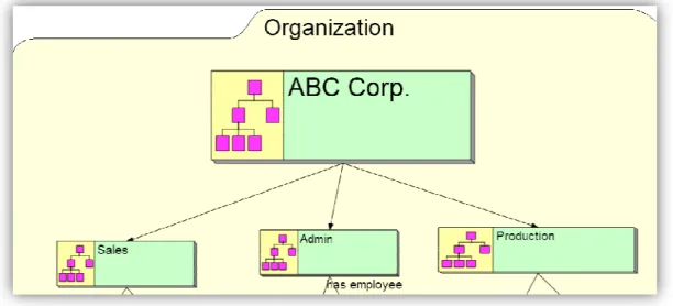
We use enterprise models which are developed in “Troux Architect 7.1”. In these models the representing elements of enterprise model are objects. And object can be process, goal, problem, actor, resource, concepts etc.
In the Figure 2-12, there are four objects ‘ABC Corp’, ‘Sale’, ‘Admin’ and ‘Production’. The type (object type) of these objects is ‘organization’. The ‘ABC Corp.’ object has ‘has-a’ relation with ‘Sales’, ‘Admin’ and ‘Production’ objects.
2 The model is found in samples of Troux Architect 7.1 tool and we modified some parts of his model
Figure 2-1: Enterprise model’s objects and their types Figure 2-2 shows the information in XML format
and ‘Admin’ and ‘Production
from “kmv” file, it is one of the file that is used by “Troux Architect Tool” to store information about enterprise model. We use this file as input to retrieve information about enterprise model.
Figure 2-2: Enterprise model’s objects and their types in ‘kmv’ file : Enterprise model’s objects and their types 2 shows the information in XML format about ‘ABC Corp.’
and ‘Admin’ and ‘Production’ objects. This part of information is retrieved from “kmv” file, it is one of the file that is used by “Troux Architect Tool” to store information about enterprise model. We use this file as input to retrieve information about enterprise model.
: Enterprise model’s objects and their types in ‘kmv’ file
about ‘ABC Corp.’, ‘Sales’, information is retrieved from “kmv” file, it is one of the file that is used by “Troux Architect Tool” to store information about enterprise model. We use this file as input to retrieve
2.1.5 Attribute & attribute value Each object can have a number of attributes
common among objects. For example, the attribute ‘country’ is co
object type ‘organization’ and ‘person’ while the attribute ‘Gender’ is only found in object type ‘person’ but not in object type ‘organization’. Figure shows the attributes of object type ‘person’ with values. The figure 2 the attributes of object named ‘David Scott’ in XML format.
Figure 2-3: Attributes and their values for object ‘David Scott’ as one see through GUI of Troux Architect
Attribute & attribute value
a number of attributes. The attributes may or may not For example, the attribute ‘country’ is common in object type ‘organization’ and ‘person’ while the attribute ‘Gender’ is only found in object type ‘person’ but not in object type ‘organization’. Figure
bject type ‘person’ with values. The figure 2 object named ‘David Scott’ in XML format.
: Attributes and their values for object ‘David Scott’ as one see through GUI of Troux Architect
attributes may or may not be mmon in object type ‘organization’ and ‘person’ while the attribute ‘Gender’ is only found in object type ‘person’ but not in object type ‘organization’. Figure 2-3, bject type ‘person’ with values. The figure 2-4 shows
Figure 2-4: Attributes of object ‘David Scott’ with respective values by : Attributes of object ‘David Scott’ with respective values by viewing the *.kmv file
2.1.6 Relations
Objects are connected with each other through relations.
figure 2-5 &2-6, ‘Admin’ object has relation named ‘has employee’ ‘David Scott’.
Figure 2-5 shows the graphical representation of relation between two objects. While the figure 2-6 shows the informatio
objects in XML format.
Figure 2-5: Relations between two objects (graphical view)
Figure 2-6: Relations between two objects
Each relation may have an inverse relation, for example, ‘David Scott’ object has ‘employed by’ relation with ‘Admin’. So, ‘has employee’ and ‘employed by’ are inverse to each other.
s are connected with each other through relations. For example, ‘Admin’ object has relation named ‘has employee’ with object
5 shows the graphical representation of relation between two objects. 6 shows the information about relationship between same
: Relations between two objects (graphical view)
: Relations between two objects in XML format
Each relation may have an inverse relation, for example, ‘David Scott’ object d by’ relation with ‘Admin’. So, ‘has employee’ and ‘employed by’ are inverse to each other.
For example, see at with object
5 shows the graphical representation of relation between two objects. n about relationship between same
Each relation may have an inverse relation, for example, ‘David Scott’ object d by’ relation with ‘Admin’. So, ‘has employee’ and ‘employed
11 2.1.7 Source and target of a relation
Each relation has ‘origin’ and ‘target’ object.In Figure 2-5& 2-6, relation name is ‘has employee’, origin is ‘Admin’ and target is ‘David Scott’ and relation named ‘employed by’ has origin ‘David Scott’ and target ‘Admin’.
2.1.8 Purposes of enterprise model
An enterprise model can be developed to serve one purpose but it could as well be used for many different purposes.Here are few formal purposes of enterprise modeling [26].
1. To capitalize enterprise knowledge and know how.
2. To illustrate relations and dependencies within the enterpriseand with other enterprises, to achieve better control and management over all aspects. 3. To provide support to business process re-engineering.
4. To get a common and complete understanding of the enterprise.
5. To improve information management across organizational and application system boundaries and provide a common means for communication throughout the organization. Rationalize and secure information flows. 6. To provide operative support for daily work at all levels in the enterprise
from top to bottom.
7. To control, co-ordinate and monitor some parts of the enterprise. 8. To provide support for decision making.
9. To provide support the design of new parts of the enterprise. 10. To simulate processes.
2.1.9 Languages& tools
A model is always expressed or illustrated in terms of a language. This language is more or less formal and is made of constructs. The most formal languages (mathematics) and less formal (natural languages) can be used to represent models. And in between these two extremes, many forms of languages exist to model things or reality such as
• Symbolic languages - an example of symbolic languages is the set of symbols for the traffic regulations.
• Graphical or diagramming languages – graphical languages is the set of diagrams (rectangles, diamonds and arcs) to represent entity-relationship models.
• Semi-formal languages - an example of semi-formal languages is the IDEF [24] notations.
12
• Formal description techniques - an example of formal description techniques is the LOTOS language [24].
There are a number of modeling languages available like GRAI, CIMOS, ITM, GEM, EEMM, IEM, EEML etc.In 90’s different commercial tools were available to make enterprise model or business process model in market like ARIS ToolSet3, METIS, Enterprise Modeller4, FirstSTEP5, KBSI, CimTool,6 MO2GO7etc [2].
In Globeman21 project, METIS 2.1 tool was used for enterprise modeling purpose. Along with otherbusiness process engineering model, an extended enterprise engineering platform was built in the course of the project. The model (extended enterprise engineering model) serves as a knowledge management tool in the extended enterprise and enables extended enterprise integration [24].
METIS was renamed as Troux Architect 8tool. Once an enterprise model is developed by EMSE and saved the information as XML file format then other tools can read this model if those have access to DTD (data type definition) of Troux Tech.
2.2
XML- Extensible Markup Language
Extensible Markup Language and abbreviated as XML, describes a class of data objects called XML application profile or restricted form of SGML (Standard Generalized Markup Language).
By construction, XML documents are conforming SGML documents. XML documents are made up of or constituted by storage units called entities; these entities may contain either parsed or unparsed data. Characters form parsed data, some of which form character data and some of which form markup. Markup encodes/contains a description of the document's storage layout and logical structure. XML provides a mechanism to apply constraints upon the storage layout and logical structure of document.
To read XML documents, a software module called XML processor is used and it provides access to the contents and structure of XML document. It is assumed that an XML processor is doing its job on behalf of another software module, called the application [8].
See figure 2-7, it shows how the information are stored in XML format.
3 http://maloy30.softarchive.net/aris_toolset_modeling_business_processes_eng_ rus.153327.html 4 http://www.hiteclabs.com/ 5 http://www.interfacing.com/ 6 http://www.cimosa.de/IctSupport/CimTool.html 7 http://www.modelbased.net/aif/solutions/singular_solutions/solution_mo2go.h tml 8 http://www.troux.com
Figure 2
Enterprise models developed through organization) are used in this research work and stored in XML format. Each
Following are Metis file types [30]. • KMV – Knowledge Model View
opened through Metis Client Too files.
• KMD – Knowledge Model Data
Views. One can load KMD files into Metis, but nothing is shown in the modeling area, only listed in the trees. It can reference other
through URI properties.
• SVG – Scalable Vector Graphic reference PNG files.
• PNG – Portable Network Graphics replaces GIF as the internet standard for 2.2.1 Origin and goals
XML was developed by an XML Working Group (
known as the SGML Editorial Review Board) in 1996. XML Working Group was formed under the auspices
(W3C). The group was chaired by Jon Bosak of Sun Microsystems. XML Special Interest Group (previously known as the SGML Working Group), it also organized by the W3C, took active part in development of XML.
Here are the design goals of XML
• XML shall be usable over the Internet straightforwardly. • XML shall provide support to a wide variety of applications.
• XML shall be compatible with SGML (Standard Generalized Markup Language).
• To write/develop programs which process XML documents, will be easy. • The number of optional features in XML shall be kept to the absolute
minimum, ideally zero.
2-7: Store information in XML format
prise models developed through Troux Architect 7.1 (product of Metis ) are used in this research work. All Metis [30] components are created and stored in XML format. Each kmv file is a set of xml tags to describe meta
Following are Metis file types [30].
Model View – contains at least one Model View. This file is
opened through Metis Client Tools. This file has reference to KMD and SVG
Knowledge Model Data – it contains any Metis entity, except Model
Views. One can load KMD files into Metis, but nothing is shown in the modeling area, only listed in the trees. It can reference other KMD, SVG and other files
Scalable Vector Graphic – contains one or more symbols. It has Portable Network Graphics – used to represent bitmaps in symbols. It
replaces GIF as the internet standard for representing bitmaps. Origin and goals
XML was developed by an XML Working Group (this group is originally known as the SGML Editorial Review Board) in 1996. XML Working Group was formed under the auspices or support of the World Wide Web Consortium . The group was chaired by Jon Bosak of Sun Microsystems. XML Special Interest Group (previously known as the SGML Working Group), it also organized by the W3C, took active part in development of XML.
Here are the design goals of XML[8]:
e over the Internet straightforwardly. XML shall provide support to a wide variety of applications.
XML shall be compatible with SGML (Standard Generalized Markup To write/develop programs which process XML documents, will be easy.
optional features in XML shall be kept to the absolute minimum, ideally zero.
product of Metis ] components are created file is a set of xml tags to describe meta-model.
contains at least one Model View. This file is ls. This file has reference to KMD and SVG it contains any Metis entity, except Model Views. One can load KMD files into Metis, but nothing is shown in the modeling KMD, SVG and other files contains one or more symbols. It has used to represent bitmaps in symbols. It
originally known as the SGML Editorial Review Board) in 1996. XML Working Group of the World Wide Web Consortium . The group was chaired by Jon Bosak of Sun Microsystems. XML Special Interest Group (previously known as the SGML Working Group), it
XML shall be compatible with SGML (Standard Generalized Markup To write/develop programs which process XML documents, will be easy.
14
• XML documents should be reasonably clear and human readable. • The XML design should be prepared quickly.
• There should be formality and conciseness in design of XML. • XML documents shall not be complex and easy to create.
The specification [8] and other associated standards (Internet RFC 1766 for language identification tags, Unicode and ISO/IEC 10646 for characters, ISO 639 for language name codes and ISO 3166 for country name codes), provides all the information that is necessary to understand XML Version 1.0 and construct computer programs to process XML.
2.3
Ontology
There are a number of ontology definitions in literature. Here are few of them. The term ‘ontology’ has its roots in philology, where ontology means a systematic description of existence. In computer science, there are different definitions of ontology but each definition tries to define ontology in three aspects, content, form and purpose of ontology [6].Ontology is specification of conceptualization[13].Ontology is the description of basic terms and their relationships and the axioms for constraining the relationships among[13]. Ontology is the science of analyzing of objects, properties of objects, events, processes and relations in every area of reality [15]. Ontology is description of the concepts and relationships among the concepts[16].
2.3.1 Enterprise ontology
Here are number of definitions of enterprise ontology found in literature.
Enterprise ontology can be defined as description of a domain and parts of domain of an enterprise. The enterprise ontology is used in an enterprise to solve specific problems of that enterprise [3].
Enterprise ontologies are usually created and organize relevant knowledge about activities, processes, organizations, strategies, marketing etc. All this knowledge is meant to be used by enterprises [32].
Enterprise ontology [1] defined as “enterprise ontology as the realization and implementation independent essence of an enterprise, in short, as the deep structure behind its observable surface structure”.
The main purpose of enterprise ontology is to promote the common understanding among people across enterprises and to serve as a communication medium between people and applications, and among different applications [33].
15
2.3.2 Approaches to develop ontology
Top-down:In top-down ontology development, process starts with the
definition of the most general concepts in the domain and subsequent specialization of the concepts. For example, if one takes the example of wine ontology, then one can start with creating classes for the general concepts of Wine and Food. Then one specializes the Wine class by creating some of its subclasses: White wine, Red wine, Rosé wine. Then one can further categorize/specialize the Red wine class, for example, into ‘Syrah’, ‘Red Burgundy’, ‘Cabernet Sauvignon’, and so on [17].
Bottom-up:In bottom-up ontology development, the process of development
starts with the definition of the most specific classes, the leaves of the hierarchy, with subsequent grouping of these classes into more general concepts. For example, one starts by defining classes for ‘Pauillac’ and ‘Margaux’ wines. Then one creates a common superclass for these two classes ‘Medoc’ which in turn is a subclass of ‘Bordeaux’ [17].
Middle-out:In middle-out ontology development, a development process is a
combination of the top-down and bottom-up approaches. Onestarts by defining the more salient concepts first and then generalizes and specialize concepts. One might start with a few top-level concepts such as ‘Wine’, and a few specific concepts, such as ‘Margaux’. One can then relate them to a middle-level concept, such as ‘Medoc’. Then one may want to generate all of the regional wine classes from ‘France’, in this way generating a number of middle-level concepts [17].
2.3.3 Components/Elements
Class - A class is a collection of objects. A class contains all objects which are
related to the associated type.
things which have certain things in common For example, see at figure 2
class ‘Organization’. The class ‘ABC_Corp.’ has three sub classes named ‘Sales’, ‘Admin’ and ‘Production’
Figure
Individuals- Instances, objects or elements of classes.
most specific concepts represented in a knowledge base [16][17]. /Elements of ontology
A class is a collection of objects. A class contains all objects which are related to the associated type.Classes or collections or concepts are
hich have certain things in common[1][16].
For example, see at figure 2-8, we have class ‘ABC_Corp.’ i.e. sub class of class ‘Organization’. The class ‘ABC_Corp.’ has three sub classes named
’, ‘Admin’ and ‘Production’.
Figure 2-8: Classes & sub classes in EO
Instances, objects or elements of classes. Individual instances are the most specific concepts represented in a knowledge base [16][17].
A class is a collection of objects. A class contains all objects which are are kinds of , we have class ‘ABC_Corp.’ i.e. sub class of class ‘Organization’. The class ‘ABC_Corp.’ has three sub classes named
Property- Properties are divided into data property and object property.
Data Property-Attributes, aspects,
parameters which classes can have [16]. In the figure 2-9, shows a
values (at right hand side)
‘xyz street’, the data property ‘privatePhoneNo’ has values ‘776
Figure 2-9: Instance with data properties (property/valu
divided into data property and object property.
Attributes, aspects, data properties, features, characteristics or parameters which classes can have [16].
shows a number of data properties (at left hand side) t right hand side), for example, the ‘street’ data property has value
’, the data property ‘privatePhoneNo’ has values ‘776-876-444’
: Instance with data properties (property/value pair)
properties, features, characteristics or (at left hand side) with example, the ‘street’ data property has value 444’ etc.
Object Property- Relations,
individuals can be related to one other [16].
In context of OWL language, the term ‘object property’ is used as a synonym to ‘relation’. Classes are related (make re
object property and instances are also related (make relation) to instances of other classes through object property.
Figure 2-10 &2-11 show the object properties among classes Organizatio Person.
Figure 2-10: Direct relation ‘has_employee’ between ‘Organization’ and
Figure 2-11: Inverse relation between ‘Organization’ and ‘Person’ classes
Domain & range- The RDF (Resource Description Framework, is
recommended by W3C) model is based on triples. It is consisting of a subject (domain), a property (object property) and object (range) [3].
In the figure 2-10, the object property ‘has_employee’ has domain ‘Organization’ class and range ‘Person’ class. While
property ‘employed_by’ has domain ‘Person’ class and range ‘Organization’ class.
Axioms–Axioms are used to represent business rules
capabilities.
Relations, object properties, slots, ways in which classes and individuals can be related to one other [16].
In context of OWL language, the term ‘object property’ is used as a synonym to ‘relation’. Classes are related (make relation) with other classes through object property and instances are also related (make relation) to instances of other classes through object property.
11 show the object properties among classes Organizatio
: Direct relation ‘has_employee’ between ‘Organization’ and ‘Person’ classes
: Inverse relation between ‘Organization’ and ‘Person’ classes The RDF (Resource Description Framework, is recommended by W3C) model is based on triples. It is consisting of a subject (domain), a property (object property) and object (range) [3].
, the object property ‘has_employee’ has domain rganization’ class and range ‘Person’ class. While in figure 2-11, the object property ‘employed_by’ has domain ‘Person’ class and range ‘Organization’
Axioms are used to represent business rules and enhance reasoning slots, ways in which classes and In context of OWL language, the term ‘object property’ is used as a synonym lation) with other classes through object property and instances are also related (make relation) to instances of
11 show the object properties among classes Organization and
: Direct relation ‘has_employee’ between ‘Organization’ and
: Inverse relation between ‘Organization’ and ‘Person’ classes The RDF (Resource Description Framework, is recommended by W3C) model is based on triples. It is consisting of a subject , the object property ‘has_employee’ has domain the object property ‘employed_by’ has domain ‘Person’ class and range ‘Organization’
19 2.3.4 Usage
Here are some of the usages of ontology models[17].
• Share common understanding of the structure of information among people and software agents.
• Enable reuse of domain knowledge. • Make domain assumptions explicit.
• Separate domain knowledge from the operational knowledge. • Analyze the domain knowledge.
2.3.5 Languages & tools
Ontology languages are formal languages which are used to construct ontologies. As ontology languages have reasoning rules, so these encoded the knowledge about specific domains and provide support to process the knowledge on the basis of reasoning rules. As the ontology languages are usually declarative languages so these are commonly based on first order logic or description logic. Here are few ontology languages [7].
Traditional ontology languages- KIF (Knowledge Interchange Format),
OKBC (Open Knowledge Base Connectivity), OCML (Operational Conceptual, Modeling Language), FLogic (Frame Logic), DOGMA (Developing Ontology-Grounded Methods and Applications)etc[24].
Ontology languages which use markup schema- Here are one of those
languages which use mark up schema to encode knowledge.DAML+OIL, OIL (Ontology Inference Layer), OWL (Web Ontology Language), RDF (Resource Description Framework), RDF Schema (Resource Description Framework Schema), SHOE (Simple HTML Ontology Extension)etc[24].
There are different tools are available to develop ontologies such as TopBraid9Composer, Protégé 10etc.
9
http://www.topquadrant.com/products/TB_Composer.html
10
2.4
OWL language
Web Ontology Language ( documents needs to be proceswhere the content of documents, only needs to be presented to humans. OWL can be used to explicitly express or represent the meaning of terms in vocabularies and the relationships among those terms. This repres
terms and their interrelationships among these terms is called
has more facilities for expressing meaning and semantics as compare to XML, RDF, and RDF-S languages, and thus OWL language has greater ability to represent machine interpretable content on the Web. OWL is a revision of the DAML+OIL web ontology language. The lessons which were learned during design and application of DAML+OIL, were used while design, development and application of OWL [4].
See figure 2-12, [3], it show presented in OWL XML syntax.
Figure 2-12: Two class definitions in OWL XML syntax [3]
anguage
Web Ontology Language (OWL) is used when the information contained in documents needs to be processed by applications and opposed to situations where the content of documents, only needs to be presented to humans. OWL can be used to explicitly express or represent the meaning of terms in vocabularies and the relationships among those terms. This representation of terms and their interrelationships among these terms is called ontology
has more facilities for expressing meaning and semantics as compare to XML, S languages, and thus OWL language has greater ability to terpretable content on the Web. OWL is a revision of the DAML+OIL web ontology language. The lessons which were learned during design and application of DAML+OIL, were used while design, development and application of OWL [4].
it shows how the two classes “Human” and “Gender” are syntax.
: Two class definitions in OWL XML syntax [3]
) is used when the information contained in sed by applications and opposed to situations where the content of documents, only needs to be presented to humans. OWL can be used to explicitly express or represent the meaning of terms in entation of ontology. OWL has more facilities for expressing meaning and semantics as compare to XML, S languages, and thus OWL language has greater ability to terpretable content on the Web. OWL is a revision of the DAML+OIL web ontology language. The lessons which were learned during design and application of DAML+OIL, were used while design, development s how the two classes “Human” and “Gender” are
21 2.4.1 Why OWL?
The semantic web is a vision for the future of the web. In semantic web, information is given explicit meaning, making it easier for machines to automatically process the information and integrate information available on the web. The semantic web will build on XML's ability to define customized tagging schemes and RDF's flexible approach to representing data. The first level above RDF required for the semantic web is an ontology language what can formally describe the meaning of terminology used in web documents. If machines are expected to perform useful reasoning tasks on these documents, the language must go beyond the basic semantics of RDF schema. The “OWL Use Cases” and “Requirements Document” provide more details on ontologies and motives which need for a web ontology language in terms of six use cases, and formulates design goals, requirements and objectives for OWL [4].
• OWL has been designed to meet this need for a web ontology language. OWL is part of the growing stack of W3C recommendations related to the semantic web.
• XML provides a surface syntax for structured documents, but imposes no semantic constraints on the meaning of these documents.
• XML Schema is a language for restricting the structure of XML documents and also extends XML with data types.
• RDF is a data model for objects ("resources") and relations between them provides a simple semantics for this data model, and these data models can be represented in XML syntax.
• RDF Schema is a vocabulary for describing properties and classes of RDF resources, with a semantics for generalization-hierarchies of such properties and classes.
• OWL adds more vocabulary for describing properties and classes: among others, relations between classes (e.g. disjoint), cardinality (e.g. "exactly one"), equality, richer typing of properties and characteristics of properties (e.g. symmetry), and enumerated classes.
2.4.2 Sublanguages of OWL
OWL provides three increasingly expressive sublanguages designed for use by specific communities of implementers and users.
OWL Lite:It supports those users who primarily need a classification among
hierarchy and simple constraints. For example, while it supports limited cardinality constraints, by using it user can write only cardinality values of ‘0’ or ‘1’. It is easy to develop such tool which can provide support for OWL Lite rather than its more expressive relatives, and OWL Lite provides a quick migration path for thesauri and other taxonomies. Owl Lite is also less complex formally than OWL DL [4].
22
OWL DL:Itsupports maximum expressiveness while retaining computational
completeness i.e. all conclusions are guaranteed to be computable and decidability i.e. all computations will finish in finite time. Ithas all OWL language constructsbut these constructs can be used only under certain restrictions. For example, a class may be a subclass of many classes (multiple inheritances) but class cannot be an instance of another class. The name of OWL DL is due to its correspondence with description logics (a field of research that has studied the logics that form the formal foundation of OWL) [4].
OWL Full:It is for users who want maximum expressiveness and the syntactic
freedom of RDF with no computational guarantees i.e. all conclusions may or may not be computable. For example, in OWL Full a class can be treated simultaneously as a collection of individuals and as an individual in its own right. OWL Full allows an ontology to augment the meaning of the pre-defined (RDF or OWL) vocabulary. It is impossible that any reasoning software will be able to support complete reasoning for every feature of OWL Full [4].
2.5
XSL
Using XSL different XSLT patterns are developed and can be developed according to different models for identification of objects of enterprise model (consider the specific object type as ‘class’ or ‘instance’ while transforming enterprise model to enterprise ontology). For example, there is an enterprise model that has objects types ‘organization’ and ‘person’. By using XSLT pattern, extra information (xml node’s attribute ‘object type’ with value class or instance) can be inserted into XML document that specifies the type of object as ‘class’ or ‘instance’.
Extensible Stylesheet Language (XSL) is a generic language to manipulate and display data in an XML document. W3C started development of the Extensible Stylesheet Language [18].
Extensible Stylesheet Language Transformation (XSLT) is a language for transforming XML documents into other XML documents [19].
Extensible Stylesheet Language Transformations (XSLT) is designed to transform XML data into some other form, most commonly HTML, XHTML, or another XML format [20].
A transformation expressed in XSLT is called a stylesheet. A stylesheet contains a set of template rules. A template rule has two parts:
1. A pattern which is matched against nodes in the source tree
2. A template which can be instantiated to form part of the result tree.
This template allows a stylesheet to be applicable for a wide range of documents which have similar source tree structures [19].
XSLT is programming language but it is based on
means that code is executed when a certain piece of data is encountered. Other programming languages like C,
execution [18].
Extensible Stylesheet Language Transformations (XSLT) language was developed by the W3 Consortium
the closest you can get to a standard on the World Wide Web[18].
XSL consists of XSL Formatting Objects (XSLFO) and XSL Transformations (better known as XSLT). The former, officially still called
vocabulary that defines elements used to specify how an XML document is to be displayed. An XML vocabulary is a set of XML tags that have been defined for a certain purpose. XHTML is another example of an XML vocabulary [18]. XSLT is a language used to manipula
an XML vocabulary. The actual manipulation of an XML document with XSLT is called transformation. Transformation is the process of creating a new document based on the original document. This process does not chan
source document [18].
Figure 2-13, [18] shows how XML document can be converted into different outputs (HTML, INDEX, Code Samples etc)
Figure 2-13: XML transformation to multiple
ng language but it is based on data-driven execution
t code is executed when a certain piece of data is encountered. Other programming languages like C,C++ and Java etc are based on event
Extensible Stylesheet Language Transformations (XSLT) language was developed by the W3 Consortium (W3C) and now has Recommendation status, the closest you can get to a standard on the World Wide Web[18].
XSL consists of XSL Formatting Objects (XSLFO) and XSL Transformations (better known as XSLT). The former, officially still called XSL is an XML ulary that defines elements used to specify how an XML document is to be displayed. An XML vocabulary is a set of XML tags that have been defined for a certain purpose. XHTML is another example of an XML vocabulary [18]. XSLT is a language used to manipulate XML structures or documents. It is also an XML vocabulary. The actual manipulation of an XML document with XSLT is called transformation. Transformation is the process of creating a new document based on the original document. This process does not chan
shows how XML document can be converted into different (HTML, INDEX, Code Samples etc)through XSLT pattern.
: XML transformation to multiple outputs [18]
driven execution, which t code is executed when a certain piece of data is encountered. Other event-driven Extensible Stylesheet Language Transformations (XSLT) language was (W3C) and now has Recommendation status, XSL consists of XSL Formatting Objects (XSLFO) and XSL Transformations is an XML ulary that defines elements used to specify how an XML document is to be displayed. An XML vocabulary is a set of XML tags that have been defined for a certain purpose. XHTML is another example of an XML vocabulary [18].
te XML structures or documents. It is also an XML vocabulary. The actual manipulation of an XML document with XSLT is called transformation. Transformation is the process of creating a new document based on the original document. This process does not change the shows how XML document can be converted into different
24 2.5.1 Usage
Because XML documents themselves don’t contain any formatting information, one needs something else to format and display the data so that it looks pleasant. With XSLT, one has a language to manipulate an XML document. From that document, one can create another document that contains formatting information, such as Hypertext Markup Language (HTML), Portable Document Format (PDF), or Rich Text Format (RTF). In addition, one can use XSLT to restructure XML documents [18].
The benefits/advantages of using XSLT are closely related to the benefits of using XML. Assume that data is either stored or communicated as XML (which is what XML is for), the benefits of XSLT are as follows [18].
• Retrieving data from data in an XML document. • Formatting data from an XML document for display.
• Translating between an XML document used for communication and a format used within a system.
• Adding new information into data on the basis of existing information or data.
2.5.2 Tools
The transformation process of an XML document is performed by a processor, which is an application (or software component) that reads an XML document and an XSLT document and applies the XSLT to the XML. XSLT processor performs transformations using one or more XSLT stylesheets, which are also XML documents. Processors are available as command-line (run able applications) and as software components that can be used in an application such as Xalan11(developed by the Apache), MSXML12 (it is the XML parser/processor developed by Microsoft), Saxon 13(is a Java-based XSLT processor developed by Michael Kay, It comes with a SAX Parser but can work with other SAX parsers as well), Sun's JAXP, XT written by James Clark, LotusXSL14from IBM Alphaworks15etc [18][20].
11 http://xml.apache.org/xalan-j/ 12 http://www.microsoft.com/downloads/en/details.aspx?FamilyID=3144b72b-b4f2-46da-b4b6-c5d7485f2b42 13 http://saxon.sourceforge.net/ 14 http://www.stylusstudio.com/xsllist/200004/post70810.html 15 http://www.alphaworks.ibm.com/
25
2.6
Model transformation approaches
A number [12] of model to model transformation approaches are available in literature. These transformation approaches are functional approach, logic programming approach, graph transformation approach and meta-model base transformation.
2.6.1 Functional approach
This approach is looking very appealing. In [12] approach, any transformation is regarded as function, this function transforms input (the source model) into output (the target model). The big disadvantage of this approach is that it becomes awkward to maintain state during transformation process.
2.6.2 Logic programming approach
A logic language[9] has a number of features which are very important for model transformation process. These features are backtracking, constraint propagation, bi-directionality of rules and unification. The logic languages also provide query mechanism, so there is no need of separate query language. The example of logic languages are Prolog or Mercury etc.
2.6.3 Graph transformation approach
Graph rewriting [9] is a powerful tool for graph transformation. Graph transformation contains transformation rules. Each transformation rule contains LHS (left hand side) graph and RHS (right hand side) graph. The rewriting rule works in this way: the LHS of a rule is matched against input graph; the matched portion of input graph is replaced with RHS of the rule.
2.6.4 Meta-model base transformation approach
This approach [11] describes mappings between different models which are created using different concepts from possibly overlapping domains. The process of transformation provides the facility to reuse the models developed by using a domain specific modeling language into another domain specific modeling language.
As most of the languages which are used to develop enterprise models and enterprise ontologies, conform meta-model structure, so model to model transformation approaches based upon meta-models can be applied to transform enterprise model into enterprise ontology.
There is need of a common basis to define the mapping between two conceptually different models. This common basis describes the source domain, the target domain and the vocabulary of transformation [11]. We have chosen meta-model as a common basis for transformation.