Research
SKI Report 2007:05
ISSN 1104-1374 ISRN SKI-R-07/05-SE
Development of an Input Model to
MELCOR 1.8.5 for Oskarshamn 3 BWR
Lars Nilsson
May 2006
SKI Perspective
Background
Assessments of the source term for Swedish nuclear power reactors are based on calculations made by means of the severe accident analysis code MAAP. This code was developed for the US nuclear industry. MELCOR is another code for severe accident analysis, developed by Sandia National Laboratories for the US Nuclear Regulatory Commission (NRC). Both MAAP and MELCOR are integrated codes that simulate the whole course of events in a severe accident from the initiating event to the source term, i. e. radioactive releases to the environment. In Sweden, MELCOR has mostly been employed in some International Standard Problems (ISPs).
In consequence of plans to increase the power in Oskarshamn 3 there is demand for a
MELCOR model that can be used for independent analyses of specific limiting transients and accidents.
Objective
The objective was to obtain an executable and complete input model for the Oskarshamn 3 that meets standard requirements for MELCOR 1.8.5. The input should work in steady-state calculations as well as in tentative accident cases. The intention was also to carry out
calculations with the MELCOR model of certain accident sequences for comparison with results from earlier MAAP4 calculations. This work will be reported separately.
Results
An input model has been prepared for the Oskarshamn 3 rector. Demonstrations calculations, at current nominal operating conditions in Oskarshamn 3 for 3300 MW thermal power, were performed for three cases: (1) initial, steady-state conditions, (2) total loss of AC power and (3) large steam line LOCA. The results are presented in the report.
Project information
SKI reference: 2005/507/200507014
Research
SKI Report 2007:05
Development of an Input Model to
MELCOR 1.8.5 for Oskarshamn 3 BWR
Lars Nilsson
Lentek
Getingstigen 14
SE-611 61 Nyköping
Sweden
May 2006
This report concerns a study which has been conducted for the Swedish Nuclear Power Inspectorate (SKI). The conclusions and viewpoints presented in the report are those of the author/authors and do not necessarily coincide with those of the SKI.
CONTENTS
ABSTRACT
SAMMANFATTNING (In Swedish)
1. Introduction 1
2. Oskarshamn 3 BWR 2
2.1 Safety Systems – Brief Description 4
3. The MELCOR 1.8.5 Code 6 4. Basic information and data for the Oskarshamn 3 model 8
5. Input Modelling 9
5.1 Organisation of the modelling work 9
5.2 Reactor Vessel and Primary System (File O3primsyst) 12 5.3 Reactor Containment, Spray and Cavity input (File O3cont) 17 5.4 Input to COR and TP, the Transfer Process Package (File O3core) 23 5.5 Decay Heat and Radionuclide Package input (File O3dch-rn) 27
5.6 The ORNL Bottom Head Model (File O3bh) 30
5.7 Control Function input (File O3cf) 34 5.8 Input to Material Properties Package (File O3material) 34
5.9 Initialization, Boundary Conditions and Transient
Definition input (File O3init) 35 5.10 Input to MELCOR (File O3melcor) 37
6. Demonstration Runs for O3 38
6.1 Initial Conditions 38 6.2 Case 1 – Total Loss of AC Power 39 6.3 Case 2 – Large Steam Line LOCA 41 6.4 Tests with the Bottom Head, BH model 42 6.5 Summary of the demonstration runs 43
7. Conclusions and recommendations 47
Acknowledgements 48 REFERENCES 49 Appendices (not included in the report for disclosure reasons)
A. Compilation of input data to MELCOR 1.8.5 for Oskarshamn 3 BWR B. MELCOR 1.8.5 Input files for Oskarshamn 3 BWR. NONBH version,
C. MELCOR 1.8.5 Input files for Oskarshamn 3 BWR. NONBH version, Case specific input for Case 2; Steam Line LOCA.
D. MELCOR 1.8.5 Input files for Oskarshamn 3 BWR. BH specific version, Case 1; Total Loss of AC Power.
Abstract
An input model has been prepared to the code MELCOR 1.8.5 for the Swedish Oskarshamn 3 Boiling Water Reactor (O3). This report describes the modelling work and the various files which comprise the input deck. Input data are mainly based on original drawings and system descriptions made available by courtesy of OKG AB. Comparison and check of some primary system data were made against an O3 input file to the SCDAP/RELAP5 code that was used in the SARA project. Useful information was also obtained from the FSAR (Final Safety Analysis Report) for O3 and the SKI report “2003 Störningshandboken BWR”.
The input models the O3 reactor at its current state with the operating power of 3300 MWth. One aim with this work is that the MELCOR input could also be used for power
upgrading studies. All fuel assemblies are thus assumed to consist of the new Westinghouse-Atom’s SVEA-96 Optima2 fuel.
MELCOR is a severe accident code developed by Sandia National Laboratory under contract from the U.S. Nuclear Regulatory Commission (NRC). MELCOR is a successor to STCP (Source Term Code Package) and has thus a long evolutionary history. The input described here is adapted to the latest version 1.8.5 available when the work began. It was released the year 2000, but a new version 1.8.6* was distributed recently. Conversion to the new version is recommended.
In version 1.8.5 there is an option to describe the accident progression in the lower plenum and the melt-through of the reactor vessel bottom in more detail by use of the Bottom Head (BH) package developed by Oak Ridge National Laboratory especially for BWRs. This is in addition to the ordinary MELCOR COR package. Since problems arose running with the BH input two versions of the O3 input deck were produced, a NONBH and a BH deck. The BH package is no longer a separate package in the new 1.8.6 code, but its models are incorporated in the COR package.
Two demonstration runs with the NONBH version were carried out, a total loss of power case and a case simulating a large steam line LOCA. The results are briefly presented and discussed in the report.
Complete lists of the input files can be found in the appendices. However, the appendices are not included in the report for disclosure reasons.
The work was done under contract from the Swedish Nuclear Power Inspectorate.
____________________________________________________________________
*) During the writing of this report still another code version, MELCOR 2.0, has been announced to be released within short.
Sammanfattning
Rapporten beskriver framtagningen av en indatamodell till koden MELCOR 1.8.5 för kokvattenreaktorn Oskarshamn 3. Indata har delats upp i ett antal delfiler som motsvarar en eller flera av de delrutiner som MELCOR-koden består av.
Indata baseras i första hand på originalritningar och systembeskrivningar som ställts till förfogande av Oskarshamns Kraftgrupp AB (OKG). Data för primärsystemen har kunnat jämföras med en indatafil för O3 till koden SCDAP/RELAP5 som använts i EU-projektet ”SARA”, där bl a SKI deltog. Vissa uppgifter har kunnat hämtas från FSAR för O3 och även från SKI-rapporten ”2003 Störningshandboken BWR”.
Modelleringen har gjorts för O3 reaktorns nuvarande drift med 3300 MWth. Avsikten är
dock att grundmodellen ska kunna användas även för studier av aktuella
effekthöjningar. Härdmodellen har sålunda gjorts med antagande av att alla patroner är av typen Westinghouse-Atoms SVEA-96 Optima2.
MELCOR är ett datorprogram för beräkning av svåra haveriers förlopp i lättvatten-reaktorer och som utvecklas av Sandia National Laboratory på uppdrag av amerikanska kärnkraftinspektionen NRC. Indatamodellen för O3 togs fram för den senaste
MELCOR-version 1.8.5 som fanns tillgänglig vid uppdragets början. En ny version, 1.8.6* har nyligen börjat distribueras.
Version 1.8.5 av MELCOR har en extra modell, BH (Bottom Head) som är avsedd för noggrannare beräkning av förlopp i nedre plenum och av tankgenomsmältning än som görs med den ordinarie COR-modellen. BH-modellen har utvecklats av Oak Ridge National Laboratory (ORNL) speciellt för BWR och är ett tillägg till COR-modellen. Emellertid uppstod problem att genomföra beräkningarna med BH-modellen vilka inte kunde lösas inom projektet. Eftersom den separata BH-rutinen har slopats i den nya kodversionen 1.8.6, och ORNLs modeller inarbetats i COR-rutinen, rekommenderas att de här framtagna indatafilerna för O3 konverteras till den nya kodversionen.
Beräkningar med MELCOR 1.8.5 genomfördes av två haverisekvenser, totalt elbortfall samt stort brott på en ångledning (LOCA) som demonstrationsfall. Resultaten
presenteras och diskuteras i rapporten.
Komplett utskrift av alla indatafiler finns i Appendix A-D. Dessa bilagor har utelämnats i rapporten med hänsyn till sekretess.
Arbetet har genomförts på uppdrag av Statens Kärnkraftinspektion, SKI.
____________________________________________________________________
*) Under rapportskrivningen har det kommit till kännedom att en nyare kodversion, MELCOR 2.0 snart kommer att vara tillgänglig.
1 Introduction
Severe accident analyses and assessments of the source term for Swedish nuclear power reactors are based mainly on calculations made by means of the severe accident analysis code MAAP. This code was developed for the US nuclear industry. MELCOR [Ref. 1] is another code for the same applications, developed by Sandia National Laboratories for the US Nuclear Regulatory Commission (NRC). Both MAAP and MELCOR are integrated codes that simulate the whole course of events in a severe accident from the initiating event to the source term, i. e. radioactive releases to the environment. In Sweden, MELCOR has mostly been employed in some International Standard Problems (ISPs).
In consequence of plans to increase the power in Oskarshamn 3 there is demand for a MELCOR model that can be used for independent analyses of specific limiting
transients and accidents. An input model to MELCOR 1.8.5 has earlier been produced for Ringhals 3 by Lentek [Ref. 2].
The objective was to obtain an executable and complete input model for the Oskarshamn 3 that meets standard requirements for MELCOR 1.8.5. Although MELCOR is originally made for parametric studies the code has been successively developed towards a so called “best estimate” code. Therefore, default and
recommended input parameters were used as far as possible.
The report describes the input preparation and the modelling of the different systems in Oskarshamn 3. The input is divided in a number of subfiles for one or more of the model packages which constitute the MELCOR code. Two demonstration calculations were performed and the results are presented and discussed.
2
Oskarshamn 3 BWR
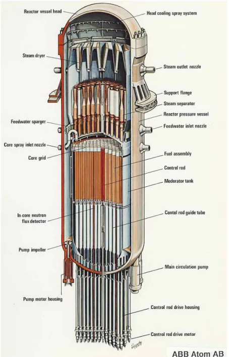
The Oskarshamn 3 (O3) Boiling Water Reactor (BWR) is located on the Baltic coast about 25 km north of the town of Oskarshamn in Sweden. It is the largest of the three BWRs at the site, all operated by the OKG AB utility. The O3 reactor was supplied by ASEA-Atom (now Westinghouse-Atom AB) and was taken into operation in 1985. O3 is an advanced 3300 MWth BWR with eight internal recirculation pumps. Operating
pressure is 7.0 MPa. The core has 700 fuel elements and 169 control rods with B4C as
absorber material. The reactor vessel is about 21 m high and has an inside diameter of 6.4 m. The 150 mm thick wall consists of carbon steel clad by stainless steel on the inside.
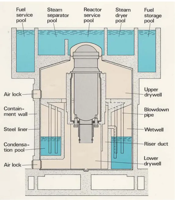
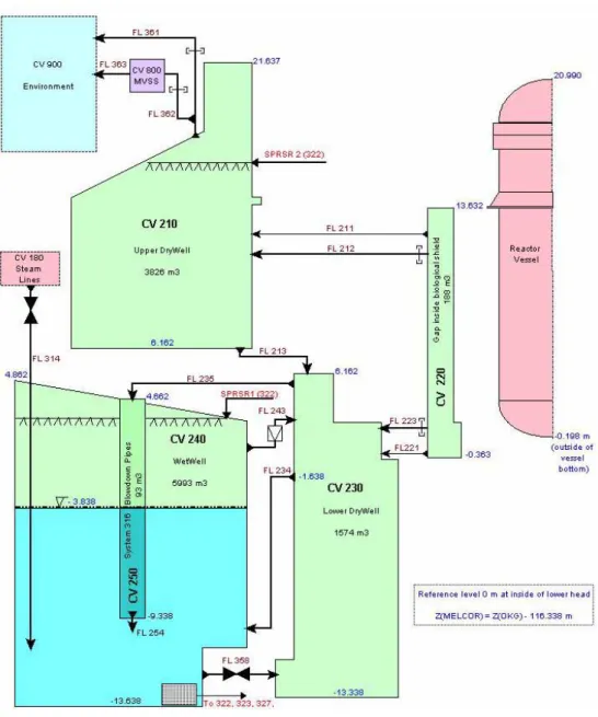
Figure 2. Principal sketch of the reactor containment
The reactor containment is of the Pressure Suppression (PS) type with vertical blowdown pipes. The outer cylindrical shell of pre-stressed concrete has a height of about 30 m and a diameter of 25.5 m on the inside. It is sealed at the top by a large steel cupola to the reactor service pools above the containment. The containment also
functions as a radiological shield to the environment. The gas volume is filled with nitrogen to prevent ignition of hydrogen if such would be generated in case of a severe accident.
The design pressure of the containment is 0.6 MPa. Two different venting systems are installed to prevent overpressurization. A pipe system with rupture disk that bursts at a pressure of 0.5 MPa facilitates filtered venting of the containment through the Multi-Venturi Scrubber (MVSS). If the containment pressure exceeds 0.65 MPa another rupture disk opens for venting directly to the atmosphere.
2.1 Safety
Systems
– brief description
This brief description of the safety systems is focusing on safety functions which are relevant for severe accident studies and which are taken into account in the MELCOR model.
At normal operation any disturbance is surveyed and correction made by automatic functions controlling reactor power, ensuring sufficient cooling and preventing radioactive releases through safeguard measures. If an abnormal failure or accident occurs there are a number of diverse safety systems which will be activated. A basic design principle is to have a high degree of redundancy and many safety functions are thus distributed on four independent subsystems.
To make a severe accident possible some of the safety systems must fail. The condition assumed here is loss of power to all cooling systems, possibly in combination with other failures as a pipe break, Loss of Coolant (LOCA) as initiating event. Some assumptions may not always be realistic, or might have very low probability, but can be of interest for parametric studies.
As a consequence, the Emergency Core Cooling Systems (ECCS), systems 323 and 327 are assumed to fail, and are not considered in the MELCOR model. System 323 is the low pressure core cooling system that begins to inject water when the back pressure goes below about 0.12 MPa and has a full capacity of around 360 kg/s per each of the four loops. Two loops inject water as top spray above the core and two loops feed into the downcomer facilitating reflooding of the core from the bottom. The high pressure system 327, the auxiliary feed water, has also four loops, all going to top spray nozzles above the core. The capacity is there totally 90 kg/s almost independent of back
pressure.
The safety systems considered for the MELCOR model are:
• The hydraulic fast actuating power shut-off system 354 (scram system) which gives full insertion of all control rods in less than 6 s after initiation. (There is also a manually activated boron shut-off system, not considered here). Scram is automatically initiated if certain conditions are fulfilled. The rather complicated control system is not modelled, instead scram conditions are set by simple control functions and the conditions are either isolation signal caused by high containment pressure, or a preset time delay.
• Pressure control and relief system 314. Sixteen valves connect to the four steam lines and the outlet pipes are forked into 64 blowdown pipes ending in the wetwell (WW) pool. Should the turbine valves close, if steam dump is not possible and after isolation of the steam lines, the 314 valves will automatically control the pressure at 7.0, maximum 7.05, MPa by steam relief to the WW. When low downcomer water level is reached system 314 will act as ADS, Automatic Depressurization System. Eight valves then open with full capacity and decrease the reactor pressure to facilitate operation of the low pressure ECCS. The ADS is initiated upon low DC level, L4, 0.5 m above core exit
combined with an environmental condition, i. e. high containment pressure. A delay of 10 minutes has been introduced before ADS opening.
• Pressure Suppression (PS) Condensation system 316 in the containment described above. This is an inherently passive system designed to limit the containment pressure. Steam leaking or blown out from the primary system to the drywell is discharged through the 24 blowdown pipes into the wetwell pool where it is condensed. Vacuum valves in eight large pipes between wetwell and lower drywell ensure that the wetwell pressure will not be higher than that in drywell.
• Containment spray, system 322. It consists of four loops with coolers, all taking water from the wetwell pool. The maximum capacity of each loop is 100 kg/s. Two loops feed spray nozzles in the upper drywell and the two others go to nozzles in the gas volume above the wetwell pool. The latter are working under normal operation to control the pool temperature at 20 C and for adjustments of the pool level. The safety functions of system 322 are to reduce the containment pressure and condense steam in the atmosphere in case of a LOCA, and to wash out aerosols that might leak out from the vessel.
• There are several other safety systems and functions to maintain the integrity of the containment, such as system 358 for flooding of lower drywell from the wetwell pool and system 362, the MVSS. These and their modelling in MELCOR are described further in section 5.3.
3
The MELCOR 1.8.5 Code
The MELCOR code [Ref. 1] is developed by Sandia National Laboratory (SNL) under contract from the U.S. Nuclear Regulatory Commission (NRC). MELCOR is a
successor to STCP (Source Term Code Package) and has thus a long evolutionary history.
MELCOR is a fully integrated code that models all phases of severe accident progression in a LWR plant. It is a so-called lumped parameter code, i.e.
zero-dimensional with respect to the modelling of hydrodynamic volumes. Thermodynamic state properties are then given in one point in each cell of the volume and considered as constant within the volume. The spatial geometry is given in input as a volume/altitude table. Each volume can have a pool and an atmosphere fraction; the latter can consist of steam and a number of non-condensable gases. Two-phase models allow for steam bubbles in the pool and water droplets, “fog”, in the atmosphere. If the non-equilibrium thermodynamics option is chosen, different temperatures and phase conditions can exist in pool and atmosphere. Space can also be occupied by other material, e.g. core
structures which can melt and relocate. This is named the virtual volume that can change the original free volume available to hydrodynamic materials.
Through connections with flow paths having lengths and inclinations sort of a three dimensional model of the reactor system can be built. The code comprises a driver module and a large number of various model packages, such as the control volume hydrodynamics package, flow path, core description, heat structure, radionuclide package, etc. The number of packages, which are engaged in the execution, is dependent on the problem to be solved.
Various severe accident phenomena in both PWRs and BWRs can be treated by MELCOR. Version 1.8.5 includes models for, among others, the following:
• Thermal-hydraulic response in the reactor coolant system, reactor cavity, containment and confinement buildings.
• Core heat-up, degradation and relocation. • Core-concrete attack.
• Hydrogen production, transport and combustion. • Fission product release, transport, and deposition.
• Impact of engineered safety features on thermal-hydraulic and radionuclide behaviour and on hydrogen combustion.
• Passive Autocatalytic Hydrogen Recombiner by the PAR package • A Bottom Head package developed by Oak Ridge National Laboratory
especially for detailed modelling of melt progression in a BWR lower head.
MELCOR calculations are executed in two steps, MELGEN and MELCOR. MELGEN is the input processor to which the majority of the input is written. It carries out the input check, and if the input is accepted it writes preliminary initial conditions to a
restart file. MELCOR then needs only a short input, mainly time-step and execution parameters for the transient calculations. Only few input data can be changed in the MELCOR input.
MELCOR runs produce a number of output files; a diagnostic (.DIA) file displaying input errors and non-fatal warnings to assist the user in debugging the input, an output text file (.OUT), a binary restart (.RST), a plot file (.PTF), and a message file (.MES). The latter announces major events in the accident progression and by means of control functions the user can flag for events of special interest such as valve actuations, containment failure, etc.
The code package also includes a graphics processor HISPLT, retained from earlier versions and which needs a special input. However, plotting is more conveniently made directly from the plot file by means of the general graphics code XMGR5, or its
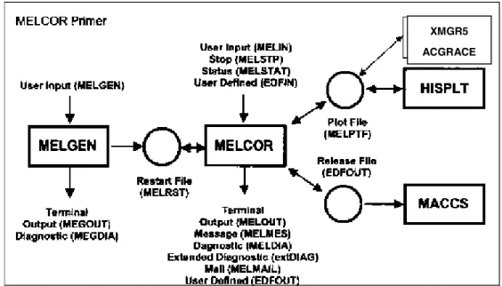
successor ACGRACE. Figure 3 below illustrates the relation between the various codes and files in the MELCOR package.
Figure 3. Relationship between the various codes and files in MELCOR
MACCS calculates off-site consequences of radioactive releases, i.e. from the source term, to the environment. The file names shown in the figure are default names which can be optionally changed by the user.
The latest released version, available to present project, was MELCOR 1.8.5, denoted “BASE CODE VERSION 1.8.5(A), SEP –25-2000, BASE CODE QZ”. This version was distributed at the 5th MELCOR User’s Workshop, May 10-15, 2001 in Bethesda, MD, USA.
A new code version, MELCOR 1.8.6 presented at the year 2005 MELCOR users workshop was released recently. This version has incorporated the Bottom Head model into the COR package. A 1.8.5 input deck needs a certain degree of upgrading before it can be run with the new code version.
XG
XMGR5 ACGRACE
4.
Basic information and data used for
the Oskarshamn model
The MELCOR input model of the O3 hardware is mainly based on original drawings and system descriptions made available by courtesy of the utility OKG AB [Ref. 3]. Other major sources of information are:
• FSAR (Final Safety Analysis Report). The latest, revised edition [Ref. 4] was studied at SKI and information relevant to the input preparation was recorded. This comprises various system descriptions and important flow diagrams. Complementary and some updated system descriptions were later obtained from OKG.
• Fuel data for the new core loading containing SVEA-96 Optima2 assemblies were made available by favour of the department of Core and Fuel Management of OKG (Classified information).
• An input file for O3 to the Severe Accident Code SCDAP/RELAP5 that was used in the EU project SARA sponsored by SKI [Ref. 5]. The SARA input models only the primary system. Since it has been quality assured it could be employed for checking of some corresponding data in the MELCOR input deck. • The so called “2003 Störningshandboken för BWR” (BWR disturbance response
handbook) [Ref. 6].
An input file for the Finnish Olkiluoto-1 BWR made available by SKI was also of some help. The Finnish deck is an updating from input to older versions of MELCOR and lacks input to the Bottom Head package.
Appendix A contains a compilation of hardware data derived from the different sources fitted to MELCOR input format.
5.
Input Modelling
5.1
Organisation of the modelling work
Since the MELCOR code consists of a number of model packages, and a full plant input is rather comprehensive, it was found suitable to spread the input set over a number of files corresponding to one or more of the MELCOR packages. These plant input files are called by the “R*I*F” command in the MELGEN execution file here named “O3init”. The MELCOR input is written to a separate file “O3melcor”. The files were edited in simple text format, (.txt).
The description of the input preparation is here divided into sections, one for each of the following files:
O3primsyst Input to the Control Volume Hydrodynamics (CVH), the Flow Path (FL) and the Heat Structure (HS) packages for the reactor vessel with steam lines.
O3core Input to the COR package for the reactor core and lower plenum. This file has also input to the Transfer Process (TP) package which is needed as an interface for transfer of core debris between other packages, viz. the COR, the Fuel Dispersal Interactions (FDI) and the Cavity (CAV) packages.
O3dch-rn Decay Heat (DCH) and RadioNuclide (RN) packages input. These together specify the composition of radionuclides and their spatial distribution, among others, the power distribution in the core.
O3cont Input for the containment to the packages CVH, FL, HS, the Containment Spray (SPR) and to the CAV packages.
O3cf Control Function (CF) input, especially for valves and pipes and safety systems in the containment. This file also contains CFs which have to be built in order to produce certain plot variables not provided otherwise by the code. Additional plot variables can be defined here.
O3material Physical property data of a large number of materials are stored in the MELCOR data base. Any other material can be introduced by
denoting it a name and specifying the properties needed. Ascending numbers from 1 and up are used for water and fluids in free spaces, i. e. in pools and in the atmosphere, to represent material in the CVH package. The numbers 1 through 3 are reserved for water, 1 for liquid (pool), 2 for mist and 3 for steam. Numbers from 4 and higher are used for non-condensable gases for which the number and material mnemonic have to be specified in the Non-Condensable Gas (NCG) input.
O3init File for initiation and case specific input. Here are the Execution (EXEC) parameters, the NCG and calls by the R*I*F command to the other input files given. This file contains also case specific input in form of Control Functions and Table Function(TF) which defines the transient to be calculated.
O3bh Input to the Bottom Head (BH) package that is based on the model developed by Oak Ridge National Laboratory especially for BWRs. This package models the vessel parts below the core support plate, i. e. the lower plenum and the lower head vessel wall and is intended to give a more detailed simulation of the damage progression there than the COR package does.
The input set can be executed with or without the BH package input. Without BH input the melt progression in lower plenum and the melt-through of the lower head is
calculated by the COR package. If the BH input is included this calculation is done by the BH package provided that certain parameter values in the COR input are changed. It was therefore considered convenient to make two complete input sets, one “NONBH” and another “BH” input deck.
The preparation of the Oskarshamn 3 input is as far as possible made according to the recommendations in the user’s manual, i. e. default values were normally used for parameters whose value can be chosen by the user. The basic input parameters are given by the Control Volume (CV), the Flow Path (FL) and the Heat Structure (HS) data, which together describe the major reactor system, except for the core for which dimensions and structure data are specified by the COR input.
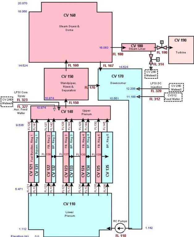
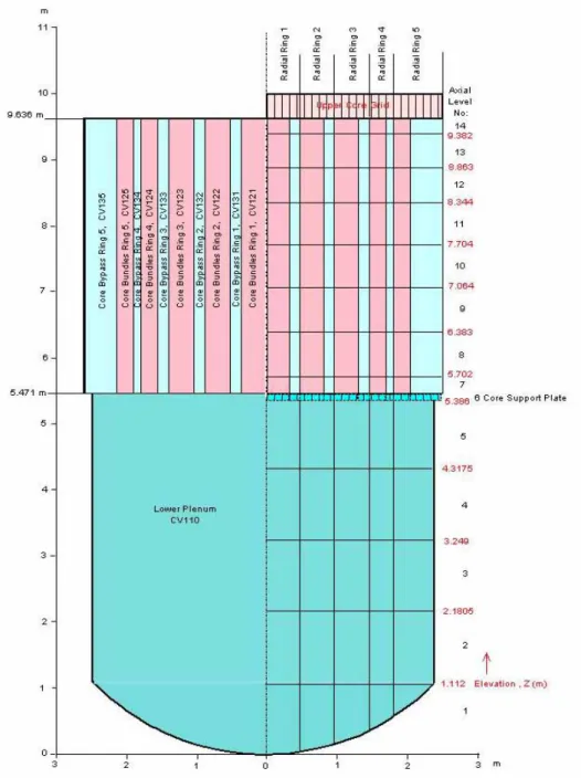
The nodalization for the reactor vessel is shown in Figure 4. Figure 5 illustrates the cross sectional division of the core. Figure 6 shows the nodalization of the containment. The MELCOR model for Ringhals 3 comprises totally 25 control volumes, 47 flow paths and 61 heat structures. The different input records are characterized by a
MELCOR package identifier (e.g. CV for the Control Volume package), followed by a component number and a record type identifier. Component numbers are assigned three digits for CV and FL and 5 digits for HS. The leading, first digit was chosen to be 1 for the primary system, 2 for containment, 3 for safety and auxiliary systems, 8 for the MVSS and 9 for the environment. In addition, control volumes can be assigned a system number by the “CVTYPEnn” record. Here number 1 was used for the primary system, 2 = containment, 3 = MVSS, 4 = environment and 5 = feed water source. All elevations must refer to a common reference point, which in the MELCOR model was chosen to be at the bottom, inside of the reactor vessel. The elevations of the O3 buildings in OKG drawings refer to another level, probably the sea level. Thus the following relation is valid:
z(MELCOR) = z(OKG) – 116.338 m
Main input data for control volumes, flow paths and heat structures are listed in Tables in Appendix A.
Only those safety systems which might be active in a severe accident are modelled. Therefore the core cooling system 323, the auxiliary feed water system 327, or the boron injection system 351 are not taken into consideration.
5.2
Reactor Vessel and Primary System (File
O3primsyst)
Data of thermodynamic volumes, flow paths and heat structures are input in this file, except for the structures in the core and in lower plenum which are specified in the O3cor file. Volumes within the reactor vessel and in the steam lines to the inner isolation valves are included. The nodalization diagram for the vessel is shown below.
The main components are the reactor pressure vessel with its eight internal recirculation pumps, the moderator tank with its support vessel, reactor core, control rod guide tubes, steam separators, steam dryers and the annular downcomer region. Outer systems, modelled here, are only the steam lines up to the isolation valves inside the
containment. Other connecting pipes as for feed water and safety injection are modelled in the file “O3init”. Some crucial dimensions of the vessel are given below:
Table 1. Main dimensions of the reactor vessel and primary system (Nominal at 20 °C)
Inside height of pressure vessel 20.870 m Inside diameter of pressure vessel 6.428 m Wall thickness of pressure vessel incl. SS plating, cylindrical part 0.161 m Wall thickness of pressure vessel incl. SS plating, bottom head 0.168 m Inner/outer diameter of moderator tank support 4.815/4.895 Inner/outer diameter of moderator tank 5.094/5.174 Number of control rods (Control rod guide tubes) 169
Number of steam separators 165 Number of steam lines 4
Total free volume in vessel, excluding steam lines 547.5 m3 Volume in steam lines up to isolation valves Appr. 23.0 m3 The pressure vessel wall material is carbon steel (ASME SA 508 and SA 533) with a 5 mm stainless steel welded plating on the inside. The bottom head has furthermore a 7 mm plating of manganese steel in between. The thermal insulation of the reactor vessel below the tank support skirt is not applied directly on the outer wall but on the inside of the biological shield with a 580 mm gap between to allow cooling and inspection. The MELCOR model of the primary system comprises 15 control volumes, 30 flow paths and 34 heat structures. The control volumes with associated flow paths and heat structures are discussed below.
5.2.1
Lower Plenum (CV110)
The lower plenum is bounded by the spherical bottom head, the cylindrical moderator tank support and at the top, the upper side of the core support plate (CSP). The free volume is reduced by the CSP, the control rod guide tubes and drive pistons, neutron and temperature measurement tubes and belonging penetration studs welded to the lower head. These heat structures are specified in the input to the COR package. The inlet flow path is from the eight recirculation pumps (RCPs) is in the lower part of the downcomer. The RCP is modelled as pump flow path of type “QUICK-CF” for which the pump head is given by a Control Function. The water flow passes through a number of slots, about 530 mm high, in the bottom of the moderator tank support where it rests on the bottom head. The water from the lower plenum enters the fuel assemblies through the 700 inlet nozzles in the core support plate. The flow paths to the bypass are through eight 14.6 mm diameter holes in the lower part in each of the 125 inner of the totally 169 control rod guide tubes. Five inlet flow paths to the fuel channels and five to the bypass are used in the MELCOR model, corresponding to the number of radial rings in the core region.
5.2.2
Fuel Channels and Bypass (CV121-125 and CV131-135)
The core region was divided into a five MELCOR rings. For a BWR each ring
comprises one fuel and one bypass parallel flow channel. One control volume was used for the whole length of each channel, which makes totally ten CVs (axial division can be made for more detailed calculations, but extends the execution time). The core region has a height of 4.165 m and goes from the upper side of the core support plate to the top ends of the fuel pins inside the upper core grid. The 700 fuel assemblies were
distributed with respect to the different inlet flow restrictions in the following way:
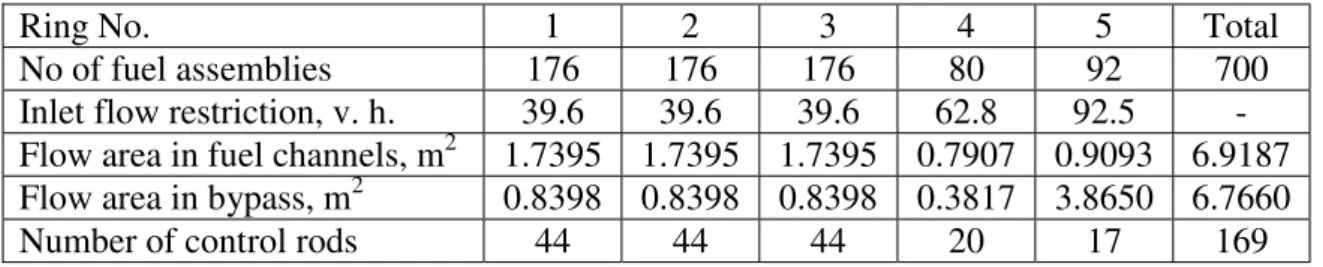
Table 2. Characteristics of the core rings
Ring No. 1 2 3 4 5 Total No of fuel assemblies 176 176 176 80 92 700
Inlet flow restriction, v. h. 39.6 39.6 39.6 62.8 92.5 - Flow area in fuel channels, m2 1.7395 1.7395 1.7395 0.7907 0.9093 6.9187 Flow area in bypass, m2 0.8398 0.8398 0.8398 0.3817 3.8650 6.7660 Number of control rods 44 44 44 20 17 169 Figure 5 below shows a cross section of the vessel at core level.
Figure 5. Cross section of vessel showing radial ring division
The bypass area is large in ring 5 since it includes the space between the outermost fuel assemblies and the moderator tank wall. The area is reduced to take into account the
four inward bends along the periphery of the moderator tank, and therefore an effective, smaller inner diameter is used in the input for the heat structure. The inner bypass areas are reduced by the space occupied by the control blades as it is assumed that the reactor is scrammed in the accident cases to be studied. The fluid volume inside the water crosses is included in the bypass volume.
The SVEA-96 Optima2 fuel bundle has three axial zones with rods of three different lengths. The full heated length is 3.68 m, but some fuel rods are shorter, 4 of 1/3, and 8 of 2/3 of full length. There are thus 96 fuel rods in the lowermost zone 1, 92 rods in zone 2 and 84 rods in zone 3, which gives a flow area that varies with height. The values given in Table 2 are average values.
There is one inlet and one outlet flow path to each fuel and bypass channel. In order to simulate free exchange of water in the moderator volume, cross flow paths are modelled between the five bypass channels.
All heat structure data of the core inside the moderator tank are specified in the COR input.
5.2.3
Upper Plenum (CV140)
The upper plenum is defined as the volume between the lower part of the core grid and the moderator tank lid at the top. The half-spherical shaped lid is penetrated by the 165 inlets to the steam separators. The free volume is limited by structures as the core grid, top ends of the fuel bundles and above them the piping of the core spray system 323 with supporting structures. The inner volume of the 323 pipes is included in CV140 since the check valves are on the outside.
5.2.4
Standpipes, Risers and Steam Separators (CV150)
This control volume consists of the inner volume of the 165 steam separator systems surrounded by the upper part of the downcomer region. A set of 5 separators forms a package enclosed by an outer steel wrapping. The geometry is rather complicated and the pipes have different lengths so the definition of the bounds can be discussed. It was decided to let the upper boundary to the steam dryer volume be at the steam outlet from the central separators.
MELCOR has no special separator model like RELAP5 with its over and carry-under parameters. Some enhancement of the separator function was instead tried to be achieved by using the flag IPFSW=2 on record CV15001, that means that all fog is returned to the pool, and the flag KFLGFL=2 on record FL17002, which implements “pool-first” in the flow path from the separators to the downcomer.
5.2.5
Steam Dryers and Dome (CV160)
This is the largest control volume in the vessel and comprises the steam dryer region and the dome volume upwards limited by the vessel upper head. In the lower part is the steam dryer package. Its volume was estimated from the weight of totally 48 000 kg.
Some of the mass consists of support structures that are assigned to the downcomer volume. In the upper part there are the dome spray piping which occupy a minor fraction of the volume.
The outer boundary of the dome volume is formed by the reactor pressure vessel. Two heat structures are defined, one consisting of the upper part of the cylindrical shell, and the other by the upper head. The wall thickness in the upper head HS is increased to take into account the large mass of the vessel flanges.
5.2.6 Downcomer
The downcomer control volume is defined as the region outside the steam separators out to the reactor vessel wall and downwards comprising the annular space between
moderator tank and reactor vessel. The upper elevation is at the steam outlet from the separators and the bottom at the edge where the moderator tank support skirt is welded to the reactor vessel lower head downstream the RCPs.
The water level in the downcomer is controlled by the feed water flow and its set point is 4.2 m above the active core at normal operation with 3300 MWth.
Heat structures in the upper part of the downcomer comprise separator wrappings, skirt and support for the separator and dryer systems, piping for core spray and auxiliary feed water and feed water spargers. In the downcomer bottom are the RCP impeller and casing. The outer boundary heat structure consists of reactor vessel wall. The mass of the various nozzles connecting to the downcomer is accounted for by increase of the wall thickness.
5.2.7
Steam Lines (CV180)
Four steam lines lead the steam from the dome to the turbine. The nozzle inner diameter is 354 mm after which the diameter increases to 530 mm in the steam pipes. It is
assumed that the isolation valves at the inside of the containment close in the studied accident cases. The internal volume in four pipes is estimated to agree with the value 23 m3 used in the SCDAP/RELAP5 file [Ref. 5].
Heat structures are the 50 mm thick pipe walls with heat insulation on the outside. To each one of the steam lines are four valves to system 314, the pressure control and depressurization system, connected.
5.3
Reactor Containment, Spray and Cavity
input (File O3cont)
This file contains CV, FL and HS input for the containment building and input to the SPR package for the containment sprays and to the CAV package for the reactor cavity. The nodalization of the containment comprises five control volumes. Another external volume simulates the MVSS scrubber and still another volume is used for the
environment. The nodalization scheme is shown in Figure 6 below.
Figure 6. MELCOR nodalization of the O3 containment
The model and the measurements are based on original drawings obtained from OKG AB. The MELCOR reference elevation is at the inside of the reactor vessel bottom which is at elevation 116.338 m according to the elevations on the drawings. There are three large volumes, the Upper Drywell, the Lower Drywell and the Wetwell. Two of
the control volumes are considerably smaller. These are the gap region around the lower part of the reactor vessel and the volume inside the blowdown pipes. The gap region, CV220 is an almost closed volume inside the biological shield with the thermal
insulation on the inside wall and is furnished with channels to facilitate separate cooling of the gap atmosphere. The volume in the blowdown pipes, CV250, is modelled
separately to simulate the level behaviour at clearing of the pipes during blowdown. The free volume was calculated from the drawing measurements taking into account the interior structures. These structures consist, in addition to concrete walls, of a large number of steel structures as pipes, pumps and valves, support steel bars, gratings, etc. The rather complicated geometry results in an uncertainty of the figure of the free volume, but the figures arrived at here are used rather than the figures from “2003 Störningshandboken” [Ref. 6]. The following values were used:
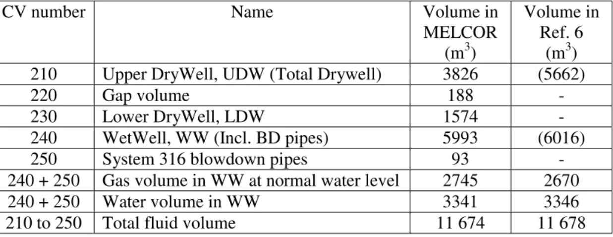
Table 3. Free volumes in the containment
CV number Name Volume in MELCOR
(m3)
Volume in Ref. 6
(m3) 210 Upper DryWell, UDW (Total Drywell) 3826 (5662) 220 Gap volume 188 - 230 Lower DryWell, LDW 1574 - 240 WetWell, WW (Incl. BD pipes) 5993 (6016) 250 System 316 blowdown pipes 93 - 240 + 250 Gas volume in WW at normal water level 2745 2670 240 + 250 Water volume in WW 3341 3346 210 to 250 Total fluid volume 11 674 11 678 Normal, initial water level in WW is 9.8 m above bottom. The atmosphere is all nitrogen. The temperature of the WW pool is kept at maximum 20 C° at normal operation by cooling through the system 322 spray. There is also another branch of system 322 with spray nozzles in upper drywell which is activated under accident conditions. Other safety systems related to the containment considered in the MELCOR model are:
• System 316, the pressure suppression blowdown system. Twenty-four 600 mm pipes go from the steam collecting cubicles in the upper part of the LDW into the WW pool ending 5.5 m below the water surface. In case of a LOCA steam blown into the UDW or LDW increases the pressure there and the steam is discharged into the pool where it will be condensed. The cold water with its large mass will effectively reduce the pressure. Pressure increase will mainly be caused by clearing of the blowdown pipes and by heating of the
non-condensable nitrogen gas in the containment.
• System 314. This pressure relief system has several functions, among others for pressure control and ADS, Automatic Depressurization. Totally sixteen DN 250 and DN 300 mm pipes go downwards in UDW from the four valves on each steam line. Each of these pipes branches into four DN 150 mm pipes above the floor to the WW, so there are totally 64 blowdown pipes leading into the WW pool. The submergence depth is there 6.9 m.
• Breakable sealing sleeves in the biological shield around pipe penetrations. The pipes for main feed water, ECCS and some other pipes go radially from the reactor vessel through the gap space, CV220 and through the thermal insulation to the UDW. In case of a pipe break close to the vessel overpressure will create a flow path through the sleeves. An opening differential pressure of 0.5 bar and a maximum flow area of 1 m2 are assumed for FL212 going from CV220 to CV210.
• Blow-out panels in the thermal insulation in the bottom of the gap volume which will burst at overpressure. An opening differential pressure of 0.2 bar and a maximum flow area of 22 m2 are assumed for FL223 going from CV220 to CV230.
• Overflow pipes from LDW to WW. There are four 600 mm pipes connecting LDW with the WW pool. If the spray is activated in the UDW, or water is blown out from a LOCA it will flow down to the LDW through the large openings in the floor between these two compartments. When the level rises to 11.7 m above the bottom of LDW water will begin to overflow to the WW (Flow path FL234). • Vacuum breakers are installed in pipes between the gas volumes of WW and
LDW to prevent overpressure in the WW. There are eight DN 450 mm pipes each with double check valves. The opening differential pressure is 0.02 bar. This flow path between CV240 and CV230 is modelled by FL243.
• System 358 – Transfer of water from WW to NDW. Two separate pipe lines each with two valves in series facilitate filling of NDW up to a level of
minimum 4 m. The system is designed to open the valves automatically in case of a severe accident at an early phase to provide cooling of falling debris from the vessel. It is here modelled by flow path FL358.
• System 361 – Venting of the containment directly to the ambient atmosphere. This is an ultimate way for pressure relief of the containment. A rupture disk in a DN 800 mm pipe that goes from the top of UDW will break at a pressure of 6.5 bar (Flow path, FL361).
• System 362 – Filtered venting to the atmosphere through the Multi Venturi Scrubber (MVSS). A DN 300 mm pipe is connected to the system 361 pipe upstream the rupture disk. The rupture disk in the pipe to the MVSS bursts at a pressure of 5.0 bar. The MVSS is assumed to have a volume of 500 m3 and the blowdown pipes be submerged about 4 m in the water pool. The MVSS is then vented to the ambient air (Flow path, FL362).
The various control volumes are described briefly in the following.
5.3.1
Upper Drywell (CV210)
The Upper DryWell (UDW) is the large annular space between the inner biological shield and the outer cylindrical containment concrete shell, plus the space above the reactor vessel upper head to the containment steel cupola. It is limited by the thick floor to the wetwell and lower drywell at the bottom (OKG elevation +122.5 m). The
concrete ceiling has a conical shape towards the opening in the centre on which the large steel cupola is mounted, which is sealed against the fuel service pool on top of the containment.
The free space is reduced by the main steam lines and a number of other insulated pipes which go from the biological shield to the isolation valves before they go through penetrations in the outer wall of the containment. The space around the top of the reactor vessel is partly occupied by thermal isolation panels. In addition, there is a substantial mass of steel from support bars, staircases, gratings and certain equipment as coolers, etc which reduce the gas volume.
Two open flow paths were defined. FL211 is a flow path from the gap volume which simulates a small leakage from the otherwise closed gap volume (CV220). FL213 models the large openings in the UDW floor next to the biological shield going down to the LDW and to the steam collecting cubicles below the floor.
5.3.2
Gap inside the biological shield (CV220)
The reactor vessel rests with its skirt on the top of the inner biological shield. Between the reactor vessel cylindrical wall and the inner surface of the 1.3 m thick biological shield there is a 0.775 m wide, annular gap, narrowing at the top. The space is partly occupied by the thermal insulation that is placed against the concrete wall leaving a gap of 0.58 m to the vessel wall. The gap volume is sealed at the bottom with insulation panels tightening around the motor cases of the RCPs and around the penetrations for control rod drives and neutron detectors. The panels are supported by the bottom radiation shield made of 120 mm thick steel plates.
The pipes for feed water, auxiliary feed water and the system 323 pipes from the vessel go through the gap and occupy, with their nozzles, some of the gap volume. In case of a pipe rupture within the gap area overpressure will open up the sealing sleeves around the pipe penetrations towards the UDW. The insulations at the bottom are designed as blow-out panels and will open a flow path to the WW.
Small leak areas are assumed to exist under normal conditions to UDW (FL211) and to LDW (FL221).
Since the thermal insulation is not placed on the vessel surface but on the inside of the biological shield the temperature of the atmosphere in the gap volume is higher than in other parts of the containment. The insulation and a cooling system are designed to limit the temperature in the concrete to maximum 65 °C. The insulation is taken into account in the MELCOR model, but not the cooling system.
5.3.3
Lower Drywell (CV230)
The Lower DryWell (LDW) consists of the central cylindrical room below the bottom radiation shield and goes down to the lower floor of the containment. The outer diameter of the cylindrical wall is 13.8 m and the wall thickness 0.8 m. The circular shape on the inside is interrupted by eight vertical strengthening bars of concrete, 1 m thick and stretching 1.6 m inwards. In the upper part the spaces between the bars are
enlarged sideways to form the steam collecting cubicles. Above them are the openings to the UDW. In the bottom of the LDW connects a duct that goes under the WW to the manhole with an air lock to the outside of the containment.
The space in LDW is occupied by various equipment. Below the reactor vessel are the RCPs and the control rod drives. There are then a large mass of structures in piping, cables, staircases, service floors, etc. which further reduces the free gas volume. Like in all outer walls, except in the WW pool, a tightening plate of carbon steel is embedded about 300 mm from the inner surface. The bottom of the DW forms the “cavity” in the MELCOR model. In case of a severe accident the cavity will be flooded from the WW by automatic opening of the valves in the connecting pipes (System 358).
5.3.4 Wetwell
(CV240)
The WetWell (WW) is the largest volume of the containment. It comprises the annular space between the outer shell and the wall to the LDW. The outer diameter is 25.5 m and the inner 13.8 m. The top of the WW is limited by the ceiling to the UDW that has a conical shape which is lower at the inside to give room for the steam collecting
cubicles. From the cubicles the 24 blowdown 600 mm I. D. pipes hang down into the WW pool. Further out are the penetrations for 64 DN 150 mm pipes of system 314. The WW is filled water to a depth of 9.8 m at normal conditions.
There are relatively few components occupying the volume. The major reduction, about 164 m3, is due to the duct in the bottom to the manhole leading to the outside of the containment. Reduction of the WW volume is done for the system 314 pipes which have an average length of 15.4 m, hanging down to 2.9 m above the bottom of WW. The volume of the blowdown pipes of system 316 is subtracted since it is defined as a separate control volume, CV250. Other structures for which reduction of the volume was made are for various staircases, gratings, and support structures and for the suction strainer packages to systems 322, 323 and 327. In the gas volume is also the other branch of the containment spray, system 322.
The concrete on the floor and a large part of the walls up to 2 m above the water surface are lined with a stainless steel plate.
The flow paths connecting to WW were mentioned before and are listed below. • FL234 –Two overflow pipes from LDW
• FL243 – Eight vacuum valves to prevent overpressure in WW, part of system 316. The opening pressure difference is 0.02 bar.
• FL254 - System 316 – Exits from the 24 blowdown pipes in the PS system • FL314 – System 314 – 64 blowdown pipes from the steam lines for pressure
relief
• FL358 – System 358 – Two pipes for filling of water from WW to LDW • SPRSR1 – System 322 – Containment spray to WW
5.3.5
System 316 Blowdown Pipes (CV250)
The 24 blowdown pipes are arranged in six bundles with four pipes in each. The bundles are evenly distributed in the area not occupied by the transport duct. The pipe dimension is D.I./D.O. = 600/612 mm. Since the pipes are mounted in the sloping roof to the steam cubicles the inlet elevation differs somewhat. Four of the outer pipes have a 90 degree bend at the inlet end, otherwise the inlet is downwards.
The water level in the blowdown pipes is the same as in the surrounding pool at normal conditions.
5.3.6
Containment Spray Package (SPR) input
The Spray Package models the heat and mass transfer between the spray water droplets and the containment atmosphere. The input specifies the location of the spray nozzles, the source volume (sump) and the control of the flow. Other input data defines the spray water temperature and droplet size and distribution.
5.3.7
Cavity Package (CAV) input
Input to the cavity package is needed for the modelling of core debris concrete interaction by the CORCON-Mod3 code in MELCOR. The concrete type is given, either as one of the built-in compositions, or as here by specifying the constituents and physical properties, which were supposed to be same as in the Ringhals 3 MAAP input. Input is also required to define the geometry of the cavity which is based on CORCON and different from the MELCOR geometry. The resolution of the nodalization is given as number of “rays”. Test runs showed that using a large number of rays, close to the maximum of 100, made the calculations more stable.
5.4
Core model. Input to COR and to TP, the
Transfer Process Package (File O3cor)
The input to the COR Package specifies the material in fuel, fuel boxes, control rods, guide tubes, etc. that is present in the core and lower plenum. These are the structures which can melt and relocate during a severe accident. They constitute the “virtual” volume in MELCOR which, when it disappears, leaves place for fluid, or when it moves can reduce the flow area of another volume. COR also includes the part of the vessel lower head directly below the core and models heat-up by the debris of the vessel wall and its penetrations, melt-through and ejection of core debris into the cavity.
The nodalization of the COR region is shown in Figure 7 below:
The radial division is the same as for the hydrodynamics control volumes, i. e. into five concentric rings which here also includes the lower plenum and goes all the way to the vessel bottom. An axial division into 14 parts was applied. The numbering is from the bottom.
Six parts were assigned for the lower plenum, one at the spherical lower head, 1.112 m high, the following four equally high, 1.0685 m and the uppermost volume containing the 0.085 m thick core support plate. The latter must not belong to the core part since it can not have both a fuel and a bypass flow channel.
The core between the core support plate and the upper core grid was axially divided into eight parts of which the middle six constitutes the active core. These are adapted to the three different zones of the SVEA-96 Optima2 fuel and each zone is divided into two equally long parts.
In MELCOR 1.8.5 there is a distinction between Supporting Structures, SS and Non-Supporting Structures, NS. NS can only support itself and failure criteria are a critical thickness and the default, or input, melting temperature. SS supports not only itself but also structures in a cell above it. For a BWR two types of SSs are valid, “PLATEB” and “COLUMN”. PLATEB applies to the core support plate. The model implies, however, that it can support only particulate debris. Support of the core in cells above requires that COLUMNS, i. e. the control rod guide tubes, below are still intact. The PLATEB can fail by yielding from the weight above when the yielding temperature is reached.
5.4.1 COR
input
Input data for the core are mainly based on information from OKG. The order and structure in the input file follows the MELCOR 1.8.5 user’s Guide, Rev. 2. The groups of required input data are:
2.1 General Core/Lower Plenum Input. Some global, geometrical and
nodalization parameters are given here, among others the fuel pin cross section measurements, melting parameters for materials and especially for penetrations. Some conditions for lower head failure and characteristics for debris are also input here.
Default values were generally used with a few exceptions; Radiative exchange factors on record COR00003 for radiation upwards between cells (FCELA) and for radiation from liquid pools to the core components
(FLPUP) were reduced from 0.25 to 0.05 as recommended in the Workshop 2000 papers which says "DEFAULTS SHOULD NEVER BE USED FOR RADIATION PARAMETERS". On record COR00009 the penetration failure temperature (TFAIL) was increased from 1273 K to 1625 K in order to avoid too early melt-through. (“Matweb” data sheet for SS304L gives a melt temperature of 1672 to 1727 K.)
2.2 Axial Level Input. This input section comprises specification of the axial cell
division and boundaries and axial power distribution (The latter is overridden by the RN input).
2.3 Radial Ring Input. The only input blocks needed are the radial ring cross
sectional area, the upper boundary heat structures and the radial power factors. Like for the axial input, the ultimate power distribution is given by the RN input.
2.4 Specific Cell Input. This is the more comprehensive part of the COR input.
The coupling between core cells and the hydrodynamic control volumes is defined here. Then, for each COR cell is given the mass of all structure materials in the cell, e. g. for fuel, spacers, fuel boxes, control rods with guide tubes. Geometric data as component and debris equivalent diameters, flow areas and surface areas are specified needed for calculation of heat transfer, flow resistance and interactions between individual cells and between cells and control volumes.
Some masses of structures used in the O3 COR input are summarised in Table 5 below. Masses were calculated from component volumes using the following constant density values listed in the MP MELCOR manual: Boron Carbide, B4C, 2520 kg/m3
Carbon steel, 7752.9 kg/m3
Steel = Stainless Steel, 7930 kg/m3 Zircaloy, 6500 kg/m3
Table 5. Masses for O3 specified in the COR input (kg)
UO2 in fuel (Optima2) 139 510
Zircaloy in fuel cladding 28 731 Zircaloy in fuel boxes 22 050 Total Zircaloy mass 50 781 Inconel in spacers 604.6 Boron carbide in control rods 1706.9 Stainless Steel in lower plenum supporting structures 34506.3 SS in core support plate incl. outer fix flange 8779.4 SS in LP Non-Supporting structures 24253.6 SS in fuel assembly inlet parts 7700.0 SS in control rod blades 18303.3 Total stainless steel, core and LP 93542.6 2.5 Lower Head Input. Here is given the ring radius’, lower head nodalization (if
not same as in the HS specification) and material specification. A simplification was made by assuming the whole inner 12 mm cladding consist of stainless steel, even though 7 mm between the basic wall material of carbon steel and the stainless steel surface is made of manganese steel. Data of the penetrations are also specified here. Two penetrations were defined, one representing a control rod and one a neutron detector stud. Input data which determine the failure behaviour are; location, mass represented by the penetration, surface and conduction area, and initial diameter of failure opening. Note, that heat transfer coefficients for lower head and the penetrations are specified on “general input” record COR00009.
2.6 COR Material Input. This input is optional and if not given the default
material and properties are used, which were adequate here for the O3 case. It should be noted that failure of a penetration or of the lower head initiates ejection of debris, but not of coolant from the reactor vessel. In order to simulate loss of coolant through the break a valve flow path has to be defined, the opening fraction of which is given by a control function. The argument is then the parameter “COR-ABRCH”, that is the break area calculated by the code.
Attention should be paid on the accuracy in input of cell measurements and volume data with respect to agreement with the figures given in CV and HS input. A consistency check in MELCOR tells if any deviation is too large. The COR volume must in any cell not exceed that specified in CV, otherwise the code aborts.
5.4.2
Transfer Process, TP, input
The Transfer Process, TP package provides an interface for a physics package to
transfer mass and energy to other packages. In current case it is prescribed to be used by the COR, CAV, FDI and RN packages to facilitate transfer of radioactive masses from the core to the cavity.
The input is given as matrices for “In” and “Out” transfer, here to/from COR and FDI (Fuel Dispersal package) and to/from FDI and CAV. The “In” transfer process number (011) for the core was input on card COR00004 in the COR package, and as “Out” transfer process number on FDI card FDI0100 for transfer from core to FDI (The FDI package input is located last in the file “O3cont”). The “OUT2 Transfer Process No. from FDI to cavity is given on record TPOT01200.
The options of input to the TP package are restricted to a few combinations of data sets. The input here was built from the examples in the manual, pages TP-UG-12—16. Note, that the transfer process numbers for radionuclide transfer must be COR and CAV numbers +500.
5.5
Decay Heat and Radionuclide Package Input
(File O3dch-rn)
5.5.1
Decay Heat Package Input
The decay heat package in MELCOR models the decay heat power resulting from radioactive decay of fission products. Decay heat is evaluated for reactor core material and for suspended or deposited aerosols and gases. MELCOR couples
thermal-hydraulic processes and fission product behaviour during the calculation.
Input data specifies the type of reactor, here BWR, and give the basis for decay power of radioactive fission products after shut down. A scram trip number has to be specified. The default ORIGEN decay curve was chosen. The other option is ANS.
The total initial reactor power is given as a sum of power from thermal fission of U235 and Pu239 plus fast fission of U238. The default values are for a BWR with a total thermal power of 3578 MW, and each of the contributing three fractions are here scaled to the actual power 3300 MWth. The default operating time, 80 % of two years was chosen.
There are built-in decay heat tables in MELCOR for a large number of elements, however not for CsI, which is used in the RN input. A new class, No. 16 had therefore to be defined on the “DCHCLSnnn0” and “DCHCLSnnnm” records. The decay heat power as a function of time must then also be specified on the “DCHNEMnnmm” records. These values for CsI were taken from the Surry input file in [Ref. 7].
5.5.2
Radionuclide Package Input
The RN package has models for calculation of radionuclide release from the fuel and debris, of transport, deposition and removal by engineered safety systems of
radionuclides in the various reactor systems. The RN package operates on the basis of material classes, which are group of elements that have similar chemical properties. Notice must be taken to the fact that some models in MELCOR use other grouping of elements, which is the case for VANESA. In these cases special mappings for transfer between the classes is needed. The following groups of data were entered according to the manual (RN-UG, section No. in brackets)
General control, Options and Mapping (3.1.1); Default values are employed as far as
possible for definition of material classes. Thus number of sections (size bins) was set to 10. The default number of classes is 16, including CsI. The hygroscopic model is turned on. The default transfer fractions for mapping of non-radioactive masses to RN material classes are applied. Mapping of the new RN class 16 for CsI to a VANESA class must, however, be specified.
Initial Radionuclide Inventories (3.1.2) is specified for the fuel only, and must be input
for each active core cell. The values are per unit mass. Axial variation is proportional to the axial power distribution taking into account the different lengths for the three axial zones in the SVEA-96 Optima2 fuel. The values are normalized to 1.0 for each radial
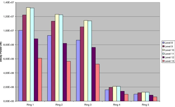
ring. The radial ring node multiplier is in proportion to the number of fuel assemblies in each ring. Since the power distribution varies with time during a fuel cycle a tentative distribution with a near symmetric axial shape was chosen. The form factor, not taken into account the internal pin power factor, is Fax = 1.21, Frad= 1.506 => Ff= 1.822, that is
relatively low. The resulting power distribution as is shown in Figure 8 below.
0,00E+00 2,00E+06 4,00E+06 6,00E+06 8,00E+06 1,00E+07 1,20E+07 1,40E+07
Ring 1 Ring 2 Ring 3 Ring 4 Ring 5
Decay P o w e r (W) Level 8 Level 9 Level 10 Level 11 Level 12 Level 13
Figure 8. Decay power per MELCOR COR cell at time zero after scram
The power distribution also applies to the fission power before scram.
Release Model Parameters (3.1.3); The default CORSOR-M model with
surface-to-volume ratio was selected, and the default for gap release temperature (1173 K). There are five additional CORSOR models to choose among.
A new acceptor class (#16) had to be defined for CsI.
Aerosol Modelling Parameters (3.1.4); Default values were used for the aerosol size
and density parameters. Only two other input groups were applied, these are for
redefinition of vertical surfaces to horizontal (RNDSxxx records), and for definition of intervolume settling (RNSETxxx). The RN models require each control volume to have at least one horizontal surface otherwise redefinition has to be made through the RNDS input. Here it was necessary only for the downcomer volume, CV110. (Another way to sidestep this is to introduce a horizontal dummy heat structure in the control volume). The RNSETxxx records facilitate settling of aerosols from volume to volume without bulk flow, which is in addition to, and independent of transport by inter-volume flow. These were here used for all vessel volumes. For the environment volume, CV900 settling into the same volume was used to keep track of radionuclides released from the containment.
Aerosol Condensation Index (3.1.5); Default “ICOND” = 0 lets condensation take place
on all aerosols.
Decay Heat Distribution (3.1.6); No redistribution was made.
ESF Parameters (3.1.7); The Engineered Safety Features (ESF) applied here is the pool scrubbing model which facilitates wash-out of aerosol and/or Iodine vapour. The
SPARC model must then be activated in the flow path input, which is here done for the system 314, 316 and the MVSS blowdown pipes. RN input parameters on record RN2PLSxx describe the type of vent and the vent pipe geometry, e. g. number and diameters of holes in the nozzle.
The containment spray input on records RN2SPRxx defines a spray partition
coefficient, here set to 5000.0, which is the ratio of concentration of iodine in the liquid droplets to that in the gas under equilibrium conditions.
There is also a block of input parameters that can be used for specification of filters for aerosols and fission product vapours. This could be used for the MVSS filter but is not applied now, since the effect of the scrubber model should be evaluated in the first place.
Radionuclide Chemistry (3.1.8): No chemical reactions were defined now. Chemisorption (3.1.9); Activated by letting ICAON = 1.
5.6
The ORNL Bottom Head Model (File O3bh)
The Bottom Head (BH) model is an extra feature originally developed for BWR applications, but can in MELCOR also be used for PWRs. The BH model is an option that replaces accident progression modelling of the debris interaction in lower plenum including failure of the lower head otherwise done by the COR model. The BH package is intended to give a more detailed simulation of phenomena in this region than the COR package. The description in the input manual is adapted to the jet-pump BWR which leaves some questions in the interpretation and application for Swedish BWRs with internal RC pumps.
The BH calculations are activated only provided that sufficient solid debris has
accumulated in the lower plenum to adequately define the initial debris bed structure as required by the BH package. Otherwise the COR models will continue to calculate the bottom head phenomena and the BH modelling will be precluded. It is therefore
necessary to change some melting parameter values in COR to inhibit COR to continue. In order to preclude prediction of penetration failure by COR an artificially high failure temperature is recommended on record COR00009. Here, this temperature was
increased from 1625 to 10000 K, and furthermore were the HTC values decreased from 1000 to 100 W/m2K.
Other recommendations with the same aim are to use low debris quenching heat transfer coefficients, and to increase the minimum allowed debris particle diameter to 0.4, in order to mitigate the maximum pressure spike that might cause premature vessel failure. Since one of the purposes with the BH package is to specifically consider the curvature of the vessel bottom head and its effect upon the shape of debris bed control volume boundaries more detailed nodalization is required for the lower plenum and lower head than for the CVH package. Accurate agreement between volume-to-elevation input in CVH and BH is necessary.
Some parameter values are not accepted by the BH package, e. g. was a heat structure multiplicity factor less than unity not accepted for the part of the lower head that belong to the downcomer (HS17001). It was therefore changed from spherical to cylindrical geometry. For the lower head below the lower plenum, however, a smaller multiplicity factor was accepted.
The following input sections are described below: 2.1 – Lower Plenum and Debris Bed Parameters.
Here is given the bottom elevation of the DownComer (DC) and the number of entries (nodes) in the specification of free fluid volume versus height in DC and Lower Plenum (LP) and of the stainless steel structure in LP. 31 and 22 nodes, respectively, were given going from the zero elevation to the underside of the core support plate. Shorter layers were used near the bottom where the curvature makes more difference. Nodes in the CV volume/elevation input had to be entered in the table for compliance with the CVH data.