SKI Report 94:15
Aging Degradation of Concrete
Structures in Nuclear Power Plants
Mark J. Do and Alan D. Chockie
September 1994
ISSN 1104-1374 ISRN SKI-R--94/15--SE
SKI Report 94: 15
Aging Degradation of Concrete
Structures in Nuclear Power Plants
Mark
J.
Do and Alan D. Chockie
Battelle Seattle Research Center,
Seattle, Washington 98105
April 1994
This report concerns a study which has been conducted for the Swedish Nuclear Power Inspectorate (SKI). The conclusions and viewpoints presented in the report
T ABLE OF CONTENTS
Executive Summary . . . . . . . . . . . . . . . . . . . . . . . . . . . . . . . . . . . . . .. vii
Chapter 1: Introduction . . . . . . . . . . . . . . . . . . . . . . . . . . . . . . . . . . .. 1
Chapter 2: The NRC's Aging Research of Concrete . . . 3
The Structural Aging (SAG) Program . . . 3
The Nuc1ear Plant Aging Research (NP AR) Program . . . . . . . . . . . . . . . . . .. 5
Chapter 3: Functions of Concrete Structures . . . 7
Safety Significant Concrete Structures . . . 7
Environmentally Exposed Concrete Structures . . . . . . . . . . . . . . . . . . . .. 9
The Designs of Concrete Containment Structures . . . 11
Chapter 4: The Sub-structures and Materials of Concrete Containment . . . 21
Sub-structures of Concrete Containments . . . 21
Materials Used in Concrete Structures . . . 23
Concrete . . . . . . . . . . . . . . . . . . . . . . . . . . . . . . . . . . . . . . . . . .. 23
Conventional Steel Reinforcement . . . . . . . . . . . . . . . . . . . . .. 24
Prestressing Steel . . . 25
Liner Plate .. . . . . . . . . . . . . . . . . . . . . . . . . . . . . . . . .. 25
Embedment Steel . . . 25
Chapter 5: Aging-Related Degradation of Category I Concrete Structures . . . 27
Stressors Affecting Concrete Structures . . . 27
Stressors Affecting the Concrete Material . . . . . . . . . . . . .. 27
Stressors Affecting the Mild Steel Reinforcement . . . 36
Stressors Affecting the Prestressing Steel . . . . . . . . . . . . . .. 37
Stressors Affecting the Liner Plate and Structural Steel . . . 40
Chapter 6: Testing Methods to Evaluate Concrete Structure Degradation . . . 47 Chapter 7: Surnrnary and Conclusions . . . . . . . . . . . . . . . . . . . . . . . . . . . .. 54 Reference .. . . . . . . . . . . . . . . . . . . . . . . . . . . . . . . . . . . . . . . . . .. 56
LIST OF T ABLES
Table 1. Summary of Stressors and Potential Affected Areas in Category I
Concrete Structures . . . 42
Table 2. Summary of Degradation Processes for BWR Steel Reinforced Concrete
Containments . . . 43
Table 3. Summary of Degradation Processes for BWR Mark II Prestressed
Concrete Containments . . . . . . . . . . . . . . . . . . . . . . . . . . . . . . . .. 44
Table 4. Summary of Degradation Processes for PWR Prestressed Concrete
Containments . . . 45 Table 5. Summary of Degradation Processes for PWR Reinforced Concrete
Containments . . . 46
Table 6. Available Non-Destructive Testing Methods to Detect Concrete Structure
Degradation . . . 48
Table 7. Available Destructive Testing Methods to Detect Concrete Structure
Degradation . . . 51
..
,LIST OF FIGURES
Figure 1. Cut-Away Diagram of a BWR Nuc1ear Power Plant Facility . . . 13
Figure 2. PWR Subatmospheric Type Reinforced Concrete Containment . . . .. 15
Figure 3. PWR Ice Condenser Type Reinforced Concrete Containment . . . .. 16
Figure 4. PWR Large/Dry Type Prestressed Concrete Containment . . . .. 17
Figure 5. BWR Mark I Type Metal Containment Enclosed in a Reactor Building. . .. 18
Figure 6. BWR Mark II Type Metal Containment Enclosed in a Reactor Building ... 19
Figure 7. BWR Mark III Type Metal Containment Enc10sed in a Reactor Building 20 Figure 8. Types of Chemical Reactions Responsible for Concrete Deterioration . . . .. 32
EXECUTIVE SUMMARY
12
This report on the aging-related degradation of concrete structures in nuclear power plants was prepared by Battelle Seattle Research Center for the Swedish Nuclear Power
Inspectorate (SKI). The purpose of this report is to provide an understanding of how concrete structures in nuclear power plants degrade over time. This report is based on the studies of concrete aging commissioned by the United States Nuclear Regulatory
Commission (NRC).
Concrete structures are significant features of a nuclear power facility. They are designed to provide:
• structural support to the mechanical and electrical systems and components; • protection of the systems and components from the environment; and • shielding against radiation releases.
Studies into the aging of concrete structures in nuclear power plants have been funded by the NRC in two separate research programs. These programs are:
• the Nuclear Plant Aging Research (NP AR) program; and • the Structural Aging (SAG) program.
The NPAR program was established by the NRC in 1983 to exarnine the aging-related degradation of all safety significant mechanical and electrical systems and components in a nuclear power plant.
In 1987 the SAG program was established by the NRC to continue the concrete aging work of the NP AR program and to gather and document the operational experience of concrete structures. Studies under the SAG program are to prov ide a technical basis to evaluate the reliability of concrete structures. The objectives of the program studies are to:
• identify significant aging mechanisms and their effect on overall structural reliability;
• assess the degraded strength of the structure over time as a result of environmental stressors and aging mechanisms;
• devise methods to assess the residual life of aged structures and how structures respond to design-basis events;
• evaluate non-destructive examination (NDE) techniques and in-plant strength measurement for assessing current condition and predicting residual life; and • document the inspection procedures, frequency, and rep air techniques.
The concrete aging studies under the NPAR and SAG programs focussed exclusively on concrete containment structures. The containment structures are where the problems resulting from nuclear power generation mainly occur. Other concrete structures of a nuclear power plant facility are considered to be conventionai structures and are not significantly affected by the nuc1ear power generation process.
FUNCTIONS OF CONCRETE STRUCTURES
Concrete structures are classified according to the location and function of each structure. Studies of concrete aging under the SAG program use two classifications to group
concrete structures. These are:
• safety significant; and • environmental exposure.
Concrete structures that the NRC classifies as safety significant are called Category I
concrete structures. Category I concrete structures perform one or more of the following safety-related functions:
• Prevention of uncontrolled liquid or airborne radiation releases; • Radiation attenuation and shielding;
• Structural support for nuc1ear steam supply system and containment internal equipment;
• Structural support for redundant safety-related equipment; • Structural support for heat sink equipment;
• Support for spent fuel pools;
• Separation or "communication" function.
The durability and performance of concrete structures also depend on the severity of the environment in which the structure is located. The SAG program researchers determined that the effects of environmental exposure need to be considered as part of the aging assessment of concrete components. Category I concrete structures are typically exposed to one or more of the seven environment categories during plant operation. These environments are:
• Subterranean;
• Direct exposure to natural environment; • Indirect exposure to natural environment; • Continuous fluid exposure;
• Fluid/pressure retaining;
• Environment inside the primary containment; and • Controlled environment inside auxiliary buildings.
MATERIALS AND STRESSORS OF CONCRETE CONT AlNMENTS
As mentioned, concrete containment structures experience the majority of nuc1ear related degradation. In order to effectively perform the functions of load carrying, radiation shielding, and leak tightness, the concrete containment structures in nuclear power plants are constructed from a number of materials. These materials include:
• eonerete;
• conventionai steel reinforcement; • prestressing steel;
• steel liner plate; and • embedment steel.
A stressor, or degradation factor, is defined as an agent or stimulus resulting from
fabrication or pre-service and operating conditions that can result in the aging process and failure of the system, structure, and component. Different materials within the concrete structure are affected by different types of stressor.
• chemical - inc1uding the chemical processes of efflorescence and leaching, sulfate attack, bases and acids attack, salt crystallization, and alkali-aggregate reactions; and
• physical - inc1uding freezing and thawing cyc1es, thermal exposure and thermal cycling, irradiation, abrasion, erosion, cavitation, and fatigue and vibration.·
The stressors affecting the mild steel reinforcement are:
• corrosion;
• elevated temperature; • irradiation; and • fatigue.
The stress ors affecting the prestressing steel include the four stress ors listed for the
reinforcing steel, with an additional stressor known as the losses of prestressing forces and end effects.
The main stressors affecting the liner plate and structural steel are corrosion and fatigue.
Summaries of the stressors and degradation processes for different types of concrete containment structures are presented in Tables 1 to 5 on pages 42 to 46. AIso included in Tables 2 to 5 are the inspection methods that are useful in identifying the potential failures of concrete structures.
TESTING METHODS FOR CONCRETE STRUCTURES
The testing methods to detect aging-related degradation of concrete structures belong in one of two categories. These categories are:
• direct methods, or destructive examinations, involve the visual inspection of the structure, and the removal of materials for testing and analysis; and
• indirect methods, or nondestructive examinations, involve the measurement of certain structural parameters based on which an estimate of the structural properties can be made using existing correlations. The structural properties inc1ude strength, elastic behavior, and the ex tent of degradation.
Presently, the detection of degradation of concrete structures is difficult since no single testing method will detect all degradation factors and processes. Combinations of testing methods are required to assess concrete structure degradation.
Tables 6 and 7, pages 49 to 52, list the non-destructive and destructive testing methods that are available and are used in the construction and general civil engineering industries. Although these testing methods are considered to be "available", many have not been used in nuc1ear power plants for various reasons.
Table 8, page 53, presents a list of the recommended testing method to detect concrete structure degradation. These recommendations are derived from the SAG researchers' evaluation of each method's technical capability based on its application in general construction practices.
SUMMARY
The conc1usions of the aging studies are:
• The performance of concrete structures have been very reliable in both nuc1ear and general civil engineering services.
• Techniques, such as visual inspection, used to detect environmentally induced deterioration of concrete can prov ide sufficient qualitative assessments of the conditions. Complications arise when quantitative data are required to assess the concrete conditions.
• Proper techniques and materials used to repair damaged concrete structures will very likely restore the structural integrity of the structure completely.
• The durability of concrete structures are well recognized by the presence and continued service of many structures several hundred years af ter construction. However, well-documented data of concrete operation al experience and longevity is lacking.
• Environmental stressors are the main causes of concrete structural degradation. These stressors typically result in localized eraeks, loss of strength, and wear of all materials within the concrete structure.
CHAPTER 1: INTRODUCTION
This report on the aging-related degradation of concrete structures in nuclear power plants was prepared by Battelle Seattle Research Center for the Swedish Nuclear Power
Inspectorate (SKI). The purpose of this report is to prov ide an understanding of how concrete structures in nuclear power plants degrade over time. The information presented in the following chapters is based on the extensive research studies on concrete
degradation sponsored by the United States Nuclear Regulatory Commission (NR C).
Concrete structures in nuclear power plants are designed to provide:
• structural support to the mechanical and electrical systems and ~omponents;
• protection of the systems and components from the environment; and • shielding against radiation releases.
The proper functioning of these concrete structures is necessary for the safety of plant personnel and the general public.
The aging-related degradation of concrete structures has been studied by the NRC under both the Structural Aging (SAG) program and the Nuclear Plant Aging Research (NPAR) program. The aging research sponsored by these programs has been directed at
understanding and mitigating the degradation of concrete structures. The goal of the research studies has been to identify the concrete component most like ly to fail, the causes of failure, how the component fails, and potential methods to mitigate the failure.
The NRC concrete aging programs are briefly reviewed in Chapter 2. The functions of concrete structures in nuclear power plants are examined in Chapter 3. IncIuded in ,Chapter 3 are cut-away illustrations of the major concrete structures at typical nuc1ear
power plants.
The next three chapters focus on the materials used in concrete containment structures (Chapter 4), the aging degradation stressors affecting nuclear plant concrete (Chapter 5), and testing methods to evaluate degradation (Chapter 6). Chapter 7 provides asurnmary of the concIusions of the concrete aging research studies.
Included in Chapters 5 and 6 are several useful tables that summarize the stress ors, degradation mechanisms, and failure modes for various concrete containment structures. Also included are tables that summarize the available and recommended destructive and non-destructive testing methods to assess concrete degradation.
CHAPTER 2: THE NRC'S AGING RESEARCH OF CONCRETE
Studies into the aging of concrete structures in nuclear power plants have been funded by the NRC in two separate research programs. These programs are:
• the Structural Aging (SAG) program; and
• the Nuclear Plant Aging Research (NP AR) program.
All concrete aging studies are performed under the SAG program since the program's establishment in 1987. Prior to 1987, the studies of concrete belonged to the NP AR program.
THE STRUCTURAL AGING (SAG) PROGRAM
In 1987 the SAG program was established by the NRC to gather and document the operational experienee of concrete structures (ORNL/NRC/LTR-92/3). Studies under the SAG program are to provide a technical basis to evaluate the reliability of concrete structures. The research activities have been performed by Oak Ridge National Laboratory in Oak Ridge, Tennessee. The objectives of the program studies are to:
• identify significant aging mechanisms and their effect on overall structural reliability;
• assess the degraded strength of the structure over time as a result of environmental stressors and aging mechanisms;
• devise methods to assess the residuallife of aged structures and how structures respond to design-basis events;
• evaluate non-destructive examination (NDE) techniques and in-plant strength measurement for assessing current condition and predicting residual life; and
At the end of each calendar year, the SAG program researchers compile a technical progress report to document the activities and products of that year. The latest technical progress report available is for the 1992 calendar year. ORNL is currently working on the
1993 rep ort. The SAG program is expected to be completed by the end of 1994. A summary of the program's accomplishments and products is expected in the middle of 1995.
The work under the SAG program has been divided into four main tasks: one management task and three technical tasks. The four tasks and the objectives of each task are
discussed below.
Program Management -The management of the technical tasks includes planning, integrating, monitoring, reporting, and technology transfer.
Materials Propert y Database - This task is designed to establish and maintain a handbook and electronic database of structural materials propert y data. The database contains information on the time-dependent behavior of structural materials. The database will be used to assist in the prediction of potential long-term deterioration of critical concrete structures, and to identify the limits of adverse environmental exposure of these structures. These information are most useful in providing an idea of the aging process for parts of the concrete structure that are not easily accessible for monitoring and testing.
It is anticipated that the materials propert y database will continue to be maintained and expanded even af ter the SAG program is officially completed in 1994.
Structural Component Assessment/Repair Technology - The two main objectives of this SAG program task are to:
• develop a methodology to quantitatively assess the presence, magnitude, and significance of any aging factors on concrete structures; and
• recommend inservice inspection and testing/sampling procedures to obtain useful data for the evaluation of current structural condition and for trending the
performance.
This task is considered by the SAG program researchers to be of primary importance for the consideration of extending the service life of nuclear power plants. This is because
the residual life of a plant cannot be determined uniess all degradation processes for each critical concrete structure in the reactor building has been examined in detail.
Quantitative Methodology for Continued Service Determinations - The objective of this task is to develop a useful method to quantitatively assess the current and future reliability of concrete structures. This task involves identifying and developing
mathematical models to evaluate changes in concrete strength based on initial conditions, service load history, and environmental exposure.
THE NUCLEAR PLANT AGING RESEARCH (NPAR) PROGRAM
Prior to the establishment of the SAG program in 1987, studies of concrete degradation were conducted under the NPAR program (NUREG/CR-4652 and NUREG/CR-4731 Vols. 1 and 2). The NPAR program was established by the NRC in 1983 to exarnine the aging-related degradation of all safety significant mechanical and electrical systems and components in a nuclear power plant (NUREG/CR-4731 YoU). Many national research laboratories in the United States have been and continue to be involved with conducting studies under the NPAR program. By 1997 the NPAR program is expected to be completed.
The objectives of the NPAR program are to:
• identify and prioritize systems, structures, and components (SSCs) with aging risk significance;
• identify, characterize, and understand aging mechanisms and the results of aging degradation, which, if not mitigated could reduce the perforrnance of the SSCs and impair plant safety;
• identify inspection, surveillance, and monitoring methods, or determine the residual life of representative SSCs which will ensure timely detection of significant aging effects before safety function is lost; and
• evaluate the effectiveness of preventive maintenance, corrective maintenance, rep air, and replacement practices in mitigating aging effects and diminishing the rate and extent of degradation caused by aging.
The NP AR researchers consider certain concrete structures in nuclear plants to be safety-significant components. Thus the aging of concrete containment structures were examined along with a number of other safety-related mechanical components in the NUREG/CR-4731
Vols. 1 and 2 studies. The studies of NUREG/CR-4652 exclusively examined the aging degradation of the concrete containment structural component.
I Eli
CHAPTER 3: FUNCTIONS OF CONCRETE STRUCTURES
Concrete structures are used to support, contain, and proteet the many mechanical and electrical systems in a nuclear power plant. The proper functioning of these structures is necessary for the safety of plant personnel and the public. This chapter discusses the functions and purposes of concrete structures in nuclear power plants.
Concrete structures are classified according to the location and function of each structure. Studies of concrete aging under the SAG program use two classifications to group
concrete structures. These are:
• safety significant; and • environmental exposure.
The functional requirements of concrete structures under each of the two classifications are described in the following sections. AIso included in this chapter is a brief overview of the different concrete containment structures used in U.S. nuclear power plants. Because of the importance of the concrete containment structures and the fact that they experience the majority of the nuclear related degradation, these structures have been the focus of the NRC sponsored aging research studies.
SAFETY SIGNIFICANT CONCRETE STRUCTURES
Concrete structures c1assified as safety significant are called Category I concrete structures. The design and construction requirements for Category I structures are
specified by the American Concrete Institute, the United States Nuclear Regulatory Guide, and the General Design Criteria for Nuclear Plants in the United States Code of Federal Regulations (CFR).
Category I concrete structures perform one or more of the safety-related functions described below.
Prevention of uncontrolled liquid or airborne radiation releases - Concrete structures, specifically the primary and secondary containment structures in which the nuclear reactor
is located, are required to prevent the release of radioactive fission products to the environment during normal plant operation and accident conditions.
All nuc1ear reactors are surrounded by a primary concrete containment structure. This structure is lined with steel on the inside surface to prevent leakage in the event of an accident.
For certain types of nuc1ear plants (some boiling water reactors) there is a large reinforced concrete building that enc10ses the primary containment structure and the reactor. This large reactor building is referred to as the secondary containment.
Figures of these structures are presented in the following sections of this chapter. A more detailed discussion of these structures are presented in Chapter 4.
Radiation attenuation and shielding - Concrete structures not only prevent the release of radiation, they also mitigate or reduce the amount of gamma radiation, neutron, and other iITadiation that occur during normal and accident conditions from reaching the outside environment. The concrete structures involved in shielding radiation are specified by the U.S. Code ofFedera.l Regulations to possess thick cross-sections to meet the limitations of allowable radiation exposure. Shielding structures include the primary or biological shield walls and the containment structure.
Structural support for nuclear steam system and containment internaI equipment - Concrete structures provide support and constraint for the many
components of the steam system. The support involves controlling the deflections and distortions of the steam systems, specifically the reactor pressure vessel, steam
generators, coolant pumps, and pipes. The supporting structures are usually made from reinforced concrete.
Structural support for redundant related equipment - The redundant safety-related equipment are used as backup for the main safety systems in the event of an accident. Most of the backup equipment is part of the cooling system and the electrical power generation system. Concrete structures used to support the back up equipment are considered to be performing a safety function. These structures inc1ude floor slabs, columns, and walls constructed from reinforced concrete.
Structural support for heat sink equipment - The nuclear reaction process produces a great amount of heat. Some of this heat must be discharged to a heat sink. The heat sink system includes piping for the intake, transport, and discharge of cooling water. This
equipment and the supporting structures are usually located outside of the containment building. The reinforced concrete structures are designed to prov ide support and anchorage of these equipment during normaloperating and accident conditions.
Support for spent fuel pools - Nuc1ear power plants have reinforced concrete pools lined with stainless steel for underwater storage of spent fuel rod assemblies and
other-potentially radioactive components. These supporting concrete structures have relatively large cross-sections in order to provide radiation shielding and meet the load support req uirements.
Protection of safety-related equipment from harmful environments - Reinforced concrete structures are designed and constructed to shield safety-related components from harmful environments, impacts from missile or high-velocity projectiles, and other physical damage.
Separation or "communication" function - During an emergency some nuclear power plants rely on concrete structures to separate or direct the pressure and suppression function of the containment. These structures conform to the leaktight requirements during plant operations. These structures typically consist of the:
• divider barrier or ice condenser in some pressurized water reactor designs; • drywell and weir walls in boiling water reactor Mark III designs; and • diaphragm floor in boiling water reactor Mark II design.
ENVIRONMENT ALL Y EXPOSED CONCRETE STRUCTURES
The durability and performance of concrete structures not only depends on the function of the structures but also on the severity of the environment in which the structure is located. The SAG program researchers determined that the effects of environmental exposure should be examined as part of the aging assessment of concrete components.
Category I concrete structures are typically exposed to one or more of the seven
environmental categories during plant operation. These environments are described below.
Subterranean - The concrete structures built below the existing level of soil/rock may be exposed to passive or aggressive effects of the environment. The sources of the degrading effects inc1ude groundwater, surrounding soils, and natural events such as floods,
below the soil/rock level include the foundation and lower walls of the primary
containment and reactor buildings, and the structures supporting the conveyance of cooling water to and from the heat sink.
Direct exposure to natural environment - The concrete structures that are exposed to the
natural environment face the following degradation processes:
• carbonation;
• wet and dry cycles;
• freezing and thawing cycles;
• chemical attack;
• ocean salt spray; and
• acid rain.
Category I concrete structures that are directly exposed to the natural environment include the primary containments, enclosure and shield buildings, and other external structures.
Indirect exposure to natural environment - Indirect exposure to the natural environment
means that the concrete structure is exposed to external temperature and humidity, but is shielded from other external conditions such as rain and wind. These structures
experience less wear than those that are directly exposed to the environment. This type of exposure is common for pipe tunnel interior surfaces where the inside environment is not controlled be heating and air conditioning.
Continuous fluid exposure - In certain cases where there is no steel liner or internai pipe,
the concrete structures supporting the intake and transport of water from the heat sink may be subjected to the constant exposure to fluids. The fluid is usually water from a cooling source such as lakes and rivers. Although the water may be chemically treated, it may contain microorganisms, solids, and chemicals potentially harmful to the concrete surfaces or reinforcing steel. The flow velocity of the fluid will affect the amount of
erosion/corrosion of the concrete.
Fluid/pressure retaining - Category I concrete structures used as a fluid or pressure
retainer are leaktight and are typically lined with carbon or stainless steel plate. The environmental effects experienced by the concrete include temperature gradients, bearing loads, and radiation fields. Examples of these structures are the concrete containment, primary reactor (biological) shield wall, spent fuel pool, and other pool structures.
Environment inside the primary containment - The concrete within the primary containment structure can be exposed to a severe environment of high humidity (up to 100% relative humidity), high temperature (6S0C or higher), and large radiation fields. These concrete structures can also experience:
• exposure to chemicals;
• the movement of heavy loads causing abrasion and impact; and
• fatigue due to loading cycles and vibrations from pumps and turbines connected to the structure.
Areas of the concrete structures where these conditions may be intensified are the surfaces around the reactor or hot piping penetrations, the area near the reactor coolant pressure boundary components, and the area near locations of fluid buildup.
Controlled environment in the auxiliary buildings - The controlled environment in an auxiliary building is achieved by heating, air conditioning, ventilation, and
dehumidification. Many of the safety-significant Category I structures are located within the controlled interior environment of the auxiliary buildings. These concrete structures are considered to be in a much less aggressive degradation environment than the concrete structures located inside the primary containment structure.
THE DESIGNS OF CONCRETE CONTAINMENT STRUCTURES
There are two principal types of nuclear power plants in the U.S. These are boiling water reactor (BWR) plants and pressurized water reactors (PWR) plants. The different designs of the containment structure are due to the different types and capacities of nuclear power plants. The primary differences of these designs are (ORNL/NRC/LTR-90/17):
• volume requirements;
• provisions for accident loadings and pressures; and • layout of the containment internai structures.
A cut-away diagram of a BWR plant is provided in Figure 1. The reactor building contains the nuclear reactor, the fuel storage pool, and the primary containment structure around the reactor (item number 21 in the figure). The auxiliary buildings include the radwaste building, the turbine generator building, and the diesel generator building. The heat sink system for this plant in the desert of Eastern Washington State consists of dry
cooling towers. As can be seen in the figure, the circulating water line (item number 19), and the pump circulating house are part of this heat sink cooling system.
Although the specific layout and design of other nuclear power plants in the U.S. and other countries will vary from the plant in Figure 1, the general information in this figure prov ides a good overview of the nuclear plant concrete structures.
There are currently 63 PWR nuc1ear plants in the U.S.,
an
with concrete containment structures. Twenty-one of these structures use reinforced eonerete. The other 42 sttuctures use prestressed eonerete. PWR concrete containments have three distinct functional designs. These are:• subatmospheric reinforced concrete illustrated in Figure 2; .. ice condenser reinforced concrete illustrated in Figure 3; and
.. large/dry reinforced and/or prestressed concrete illustrated in Figure 4.
There are currently 12 BWR plants in the U.S. having three disrlnct types of concrete containments. The number and types of containments are:
.. two Mark I reinforced concrete containments illustrated in Figure 5; .. six Mark II reinforced concrete containments illustrated in Figure 6; .. to Mark III reinforced concrete containments illustrated in Figure 7; and .. two Mark II prestressed concrete containments.
The BWR reactor shown in the Figure 1 cut-away diagram is an example of a BWR Mark II reinforced concrete containments. The components and materials used to construct these containment structures are similar and are discussed in the following chapter.
I
~ R EAC"T'O R
!
DomeS'T'EEI. CONTAINMENT t.INER TROt.t.EYS 1 2 PR ESSURIZER , " ;.
~~~'
.
. :: ._0 .:; ... ,.~~: .. : ... _ .•.. -...-__ _ . ' . . ' . .......
. '..
. ' ....-
..
:-.. Concrete Contalnment Vessel BasematFigure 2. PWR Subatmospheric Type ReinfOl'ced Concrete Containment. Source: (ORNL/NRC/L TR-90/17)
_ - - - 1 1 3 ft 10 of liner _ _ _ _ _ _ _ _ _ _
.1
I
Insmll::enf'
~CI:I -~~./
C1Cls-l!a \the-" :tre3
inoiC:21!S de ad e::d YO(llme
,
.
Pre~surizet enCIO$lIfC Controi r:d dr iv! , r.u$sile snleid '), I Cline wall OperatJn& iloa ".
~~ __ r-I.ower reactor c;vily
.~
.
"
"•
=
Figure 3. PWR lee COlldellser Type Reillforeed Conerete Containment.
~---'~'--- ---~ S'TUM GENEP.AjOP.S SE.AI. T A ISl. E INoCCRE IN$jRUME!'oIT GUlce TU8ES
RUCTOPl VESSEl. RUC'TOA C':'VITY
209'
, ".a~
t
Figure 4. PWR Large/Dry Type Prestressed Concrete Containmcnt.
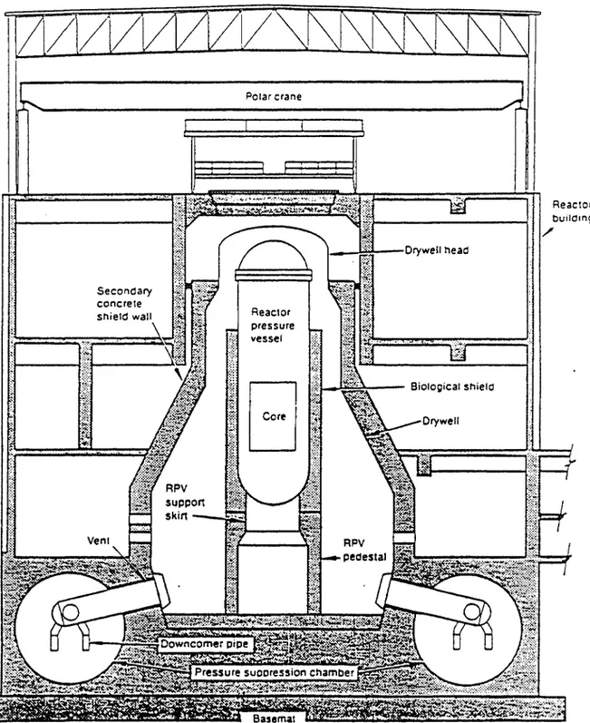
Secondary concrele shield wall POlar crane I _ _ ~:--Drywell head 1:4-~=--- Biological shield ReaClor builOInQ /
Figure 5. BWR Mark I Type Metal Containment Enclosed in a Reactor Building. Source: (ORNL/NRC/LTR-90/17)
.
-~r::=~=-l.1$~~~~~r:=-==Jr-l·
..
W:.· _ _ _ Reactor Fuel storage : ~ building pool ::~~:~
[rr==Tf==':1::U.~~_4JUlk1
..
~:r· ----ffi---{§t:;:~--_
Drywell Mad'Y
Reactor '4; pressure~~r!iimmfT1~~Si~t-f~
vessel1\
.~
_
.
I corel'
~rA
.~~
.. >
-Seconcary concrete shield wall Free-s:anding Sleef drywell Expansion gap.~
Siological shield Downcomer Pressure suppression chamber-
Waler level-
Embedded shelJ region . _ _ . Concretebas~mat
_.,Figure 6. BWR Mark II Type Metal Containment Enclosed in a Reactor Building.
Polar crane
Upper conlainment pool
Pressure
suppression ~~~!!:! ~I-I-_ pool
2.5·ft concrete
(detail drawing not to scale)
Reaclor pressure vessel Biological shield Drywell wall Horizontal vents
iI~~
Containment basematFigure 7. BWR Mark III Type Metal Containment Enclosed in a Reactor Building.
CHAPTER 4: THE SUB-STRUCTURES AND MATERIALS OF CONCRETE CONTAINMENT STRUCTURES
The concrete structure aging studies under the NPAR and SAG programs focussed exclusively on concrete containment structures. According to these NRC program
researchers, the containment building is where the problems resulting from nuclear power generation mainly occur. Other concrete structures, or auxiliary buildings, that surround the reactor building are considered to be conventionai civil engineering structures and are not significantly affected by the nuclear power generation process.
The sub-structures and problems experienced by the concrete containment are discussed in the remainder chapters of this report.
SUB-STRUCTURES OF CONCRETE CONT AlNMENTS
The large containment structures of both PWR and BWR nuclear plants are comprised of a number of similar sub-structures. These sub-structures are the:
• primary containment structure; • containment internal structures; • reactor building; and
• fuel storage pools.
Primary containment structures -These structures are designed for maximum radiation absorption. The primary containment structure can be seen in Figures 2 to 7. In Figures 5 and 6, the primary containment is labeled as the "secondary concrete shield wall" and is enclosed in a secondary concrete structure called the reactor building.
The operating requirements for the primary containment structures in PWR and BWR nuclear power plants are similar. These requirements are to:
• provide an essentially leaktight barrier against uncontrolled release of radioactive substances in all design basis accident conditions;
• withstand the predicted pressure and temperature conditions resulting from a loss of coolant accident;
• with stand periodic leak-rate testing at the highest pressure level that may occur in an accident;
• perrnit periodic inspection and testing of all significant components and surfaces; and
• support all core internal systems using the foundation, or basemat, to transfer loading to the ground.
Containment internai structures - The containment internai structures of both PWR and BWR plants typically contain floor slabs, walls, and columns. These structures perform one or more of the following functions:
• radiation shielding;
• provisions for personnel accessibility;
• nuc1ear steam systern and other internals components anchorage, support, and proteetion;
• resistance to jet, pipe whip, and other loadings in emergency conditions; • lateral stability for containment;
• transfer of containrnent loads to foundation below;
• channeling or routing the steam and air through ice condensers in PWR ice condenser containments.
Reactor building . The reactor buildings prov ide a secondary boundary for radiation containment. The reactor building can be seen in Figures 5 and 6. These structures are typically made of reinforced eonerete. These safety-related structures perform the following functions:
• provide additional shielding in conjunction with the primary containment; • resist environmental and operationalloadings; and
• enclose safety-related rnechanical equiprnent, spent fuel, and the primary metal or concrete containrnent.
Fuel storage pools - The fue! storage pools are designed to store new-fuel and spent-fuel rods. These structures are typically four walls with a bottom slab all made from
reinforced concrete. The insides of the walls and slab are lined with stainless steel. These structures generally have large cross-sections in order to support large pools of water. The fuel storage and other pools in BWR plants are located within the reactor building (see items number 2 and 8 in Figure l). The storage pools for PWR plants are typically located in an auxiliary building near the containment building.
MATERIALS USED IN CONCRETE STRUCTURES
In order to effectively perform the functions of load carrying, radiation shielding, and leak tightness, the concrete structures in nuclear power plants are constructed from a number of materials. These materials include:
• concrete;
• conventionai steel reinforcement; • prestressing steel;
• steel liner plate; and • embedment steel.
These materials are reviewed below.
Concrele
The concrete used in safety-related Category I structures contains the following ingredients:
• Type II portland cement; • fine aggregates such as sand; • water;
• other ingredients to enhance concrete properties and performance; and • normal weight or heavy weight coarse aggregate.
Type II portland cement is used because, in comparison to Type I portland cement, it has improved sulfate resistance and lower heat of hydration. Type II portland cement is also the main ingredient in many large concrete civil engineering structures such as buildings and dams.
The water and coarse aggregates are usually acquired locally at the site of the nuclear plant. Both materials undergo testing and material characterization before being used. The coarse aggregates include gravel, crushed gravel, or crushed stone. The coarse aggregates for primary containment concrete structures are dense or heavyweight aggregates. These materials include barites, limonites, magnetites, and ilmenites.
Sand and other ingredients are added to the concrete mixture to:
• improve air entrainment for enhanced durability; • improved workability;
• modify hardening or setting characteristic; • aid in curing;
• reduce evolution of heat; and
• prov ide other concrete propert y improvement.
The specified unconfined compressive strength for concrete ranges from 13 MPa to 55 MPa (mega pascal). Commonly, the compressive strength of concrete is about 28 MPa.
ConventionaI Steel Reinforcement
The conventional, or mild, reinforcing steels within concrete structures are used to resist and transfer the primary tensile and shear stress. This steel is made of plain carbon steel bar stock with lug or protrusion deformations on the surface. These steel bars conform to the manufacturing standards and specifications developed by the American Society for Testing and Manufacturing (ASTM). The minimum yield strength of these bars ranges from 270 MPa to 415 MPa. Commonly, the yield strength is 415 MPa.
Conventionai reinforcing steel includes:
• welded wire fabric; • deformed wire;
• bar and rod mats; and
• all accessory steel parts such as the seats and ties for positioning and placing the reinforcemen t.
Prestressing Steel
Some concrete containment structures use prestressing steel tendons to provide resistance to tensile loads. These tendons are in tubes and are embedded inside the concrete. These tendon tubes are typically filled with organic corrosion inhibitors. Prestressing tendons are tensioned and anchored to the hardened concrete structure by buttonheads, wedges, or nuts. There are three types of tendons: wire, strand, or bar. The standards for these prestressing steels are specified by ASTM, with the minimum ultimate strengths ranging from 1035 MPa to 1860 MPa.
Liner Plate
The leakproof characteristic of concrete containment structures is provided by the liner plate. The typical liner plate is made from steel with a thickness less than 13 mm.
Separate plates are joined by welding, and are attached to the concrete by studs, structural steel shapes, or other steel products.
The dry-weIl sections of BWR and PWR containments are usually lined with carbon steel. The linings of the wet-well and the fuel pool containments are made from various stainless steel. The manufacturing standards and perfonnance specifications for the se steels are developed by ASTM and the American National Standards Institute (ANSI).
Embedment Steel
Embedment steel is used to anchor heavy equipment such as structural members, piping, ductwork, and cable trays to the concrete. The embedment steel is designed to meet certain requirements including:
• ease of installation;
• load capacity;
• susceptibility to vibration;
• preload retention;
• temperature range;
• corrosion resistance; and
• ease of inspection.
The loads experienced by the embedment steel include a combination of tension, bending, shear, and compression. The embedment anchors include embedded bolts, grouted bolts,
embedded studs, expansion anchors, and wedge anchors. The embedded steel may also be made from material similar to that of the structural plates used during concrete placement The embedment steel material specifications also follow the standards of ANSI and ASTM.
-CHAPTER
5:
AGING-RELATED DEGRADATlON OF CATEGORYI
CONCRETE STRUCTURESThe reliability and longevity of Category I safety-related concrete structures depend on the ability of these structures to with stand the time-dependent deterioration. Concrete
reliability and longevity can be improved by limiting the exposure of the concrete structures to deteriorating effects and by proper inspection and maintenance methods. The aging research of concrete structures is to identify and mitigate the time-dependent deterioration forces on concrete. In these studies, the researchers reviewed the operational experience of concrete structures used in nuc1ear service in order to gain an understanding of how these structures are likely to fai!. This chapter presents the findings of these studies inc1uding the stressors affecting concrete, the resulting failure modes, failure mechanisms, and failure causes.
STRESSORS AFFECTING CONCRETE STRUCTURES
A stressor, or degradation factor, is defined as an agent or stimulus resulting from
fabrication or pre-service and operating conditions that can result in the aging process and failure of the system, structure, and component. Different materials within the concrete structure are affected by different types of stress or (NUREG/CR-4652 and ORNL/NRC/LTR-90/17). The four principal materials (concrete, mild steel reinforcement, prestressing steel, and linerlstructural steel) and their likely stressors are discussed below. Included at the end of this chapter are tables that summarize the infonnation on stressors, degradation
mechanisms, potential failure modes, and in-service inspection methods. Also inc1uded is a table that presents a summary of the stressors and potential degradation sites for various materials examined in this chapter.
Stressors Affecting the Concrete Material
Operational experience indicate that concrete can be highly reliable and requires no maintenance provided the concrete is:
• produced with high quality control; and • subjected to proper construction methods.
Despite the high reliability, certain environments can expose the concrete to potential stressors. Each of these stressors belong in one of two categories: chemical or physical stressors. These stressors cause concrete deterioration by adversely affecting the· performance of the cement-paste matrix or the aggregate ingredients in the concrete. Chemical Stressors on Concrete Material
These stressors are a result of the chemical reactions between the environment and the cement paste or the coarse aggregate. The chemical reactions typically occur at concrete surfaces and between cracks. However, the entire cross-section of the structure can be affected by the presence of cracks and prolonged exposure.
The degree to which chemical stressors affect the concrete material depends on the pH of the attacking fluid and the concrete's permeability, alkalinity, and reactivity. Chemical stressors attack the concrete structures in various processes. These different processes are:
• efflorescence and leaching; • sulfate attack;
• bases and acids;
• salt crystallization; and • alkali-aggregate reactions.
Each of these processes of chemical attack on concrete is discussed below.
Efflorescence and Leaching
Efflorescence is a result of the dissolution of salts contained in the cement matrix
following the percolation of water through the concrete material. The salt is leached out of the concrete and crystallized at the surface when the water is evaporated or when interaction with atmospheric carbon dioxide occurs. Efflorescence is considered by the researchers to be an aesthetic problem and not a performance degrading problem.
Efflorescence by itself indicates that changes to the cement paste are occurring within the concrete.
Leaching is a mild chemical stress or that alters the cement paste matrix by dissolving elements containing calcium through hydrolysis. The leaching rate depends on the cement's permeability, temperature, and reactivity. The primary effect of leaching is an increase in
pores and permeability of the concrete. The resulting changes in concrete due to leaching are:
• lower compressive strength;
• more vulnerable to environmental attacks such as water saturation and freeze/thaw cycles; and
• corrosion of the steel reinforcements due to chioride penetration.
The Category I structures that are most susceptible to leaching are those structures that are exposed to rain water, cooling water, or ground water.
Sulfate Attack
Sulfate attack has deteriorated a number of concrete structures that are in contact with alkali soils and waters. The chemical attackers inc1ude sulfates of sodium, potassium, and magnesium. These sulfates react with the hydrated lime and calcium aluminate in cement paste to form calcium sulfate and calcium sulfoaluminate. These resultant elements can cause the following concrete deterioration:
• considerable expansion and disruption or cracking of the concrete; and • reduction in the cohesion of the cement hydration leading to loss of strength.
The rate of sulfate attack depends on the reactivity of the cement paste and the
concentration of the sulfate compounds in the environment. The researchers determined that sulfate levels in soils and waters of 1200 ppm (parts per million) and higher can aggressively attack concrete used in nuclear power plants.
Bases and Acids
Bases and acids are addition al types of chemical attacks on concrete structures. Bases are compounds that dissolve in water to produce OH" ions. Bases and acids readily react with each other to produce a neutral solution. The hydrated cement paste is an alkaline
material with a pH level of 12.5 or higher. Thus the cement/concrete will not likely react with other basic solutions. Nevertheless, concrete deterioration by processes other than
chemical reaction with hydroxide ions (OH-) is possible when the concrete is in prolonged contact with high concentrations of alkaline solutions from water treatment or other industrial processes_
Acidic solutions are naturally more reactive to the basic cement/concrete structures. Acids are compounds that dissolves in water to produce H+ ions. Examples of acids that
surround nuclear plant concrete structures include:
• sulfuric acid in ground water; • carbonic acid in gro und water, and
• certain plant internai fluids such as boric acid.
The acidic solutions and portland cement paste chemically react by exchanging cations. This reaction produces calcium salts. The salts can be removed from the concrete internals by the leaching process described above, resulting in the increase of concrete porosity and permeability. The rate of acidic chemical attack on concrete depends on the pH of the fluid and the duration of exposure. The structures of primary concern are those Category I structures below ground and are exposed to potentially acidic ground water.
Salt Crystallization
Salt crystallization occurs when the concrete contacts water containing large amounts of dissolved solids such as calcium sulfate (CaS04), sodium chioride (NaCI), and sodium
sulfate (Na2S04). This type of water can permeate the concrete and evaporate, leaving the
salts to crystallize within the concrete pores. The repeated cycles of evaporation and crystallization can cause the amount of salt deposits increase. This increase in salt deposit can approach the level where the stresses generated are high enough to cause micro-cracks in the concrete. Concrete structures susceptible to salt crystallization damage are those in contact with fluctuating water leve Is or with salted gro und water.
Alkali-Aggregate Reactions
Alkali-aggregate reactions involve the presence of alkali ions in portland cement, hydroxyl ions, and certain silicon-type ingredients present in aggregates. The occurrence of
Alkali-aggregate reactions are due to the following factors:
• moist environment; and
• presence of reactive silica, silicate, or carbonate aggregate materials.
Alkali-aggregate reactions deteriorate concrete structures through the process of alkali-silica reaction. This reaction involves the swelling of the alkali-alkali-silica gel when in contact with water, causing an increase in hydraulic pressure within the concrete. Other alkali-silica reactions involve the sand-gravel and the sedimentary rock aggregates contained in rivers
This process can cause significant eraeking of concrete and loss of mechanical properties. The primary structures most susceptible to alkali-aggregate reactions are the Category I concrete structures exposed to rain, ground water, cooling water, or humidity inside containment areas.
Concrete deterioration due to alkali-aggregate reactions typically occur within 10 years af ter plant construction, but some structures show no sign of deterioration until 15 to 25 years after construction. This delay indicates that there is a less reactive form of silica to hinder these reactions. The deterioration of concrete is in the form of map or continuous cracking, popouts, and spalls. These blemishes can be visually detected and repaired. However, the repair cost and effon may be substantiai if the deterioration occurs in certain Category I structures such as the primary containment. Figure 8 summarizes the
V.l
N
DETERIORA TION OF CONCRETE B y CHEMICAL REACTIONS
"
,
B A C
EXCHANGE REACTlONS BETWEEN REACTlONS INVOlVING HYDROlYSIS REACTlONS INVOlVING AGGRESSIVE FLUID AND COMPONENTS
-
AND lEACHING OF THE COMPONENTS FORMATION OFOF HARDENED CEMENT PASTE OF HARDENED CEMENT PASTE EXPANSIVE PRODUCTS
I II III
I I
REMOVALOF R E MOV AL OF CaHIQNS SUBSTITUTION
CaH /ONSAS AS NON-EXPANSIVE REACTIONS REPLACING SOlUBlE PRODUCTS INSOlUBLE PRODUCTS C.H INC-5-H
I
,
I
• INCREASE IN POROSITY INCREASE IN
•
..
AND PERMEABIUTY INTERNAl STRESSI
' - - - -
--,
~
+
+
+
,
I
+
lOSS OF LOSS OF INCREASEIN lOSS OF CRACKING.
AlKAUNITY MASS DETERIORA TION STRENGTH SPAlllNG. DEFORMATION PROCESSES AND RIGIDITY POPOUTS
- - - -_ .. _
-Figure 8. Types of Chemical Reactions Responsible for Concrete Deterioration. A: Softwater attack on calcium hydroxide in hydrated portland cement; B(I): Acidic solution forming soluble calcium compounds; B(II): Solutions of oxalic acids and its salts, forming calcium oxalate; B(III): Long-term seawater attack; C: Attacks of sulfate and alkali-aggregate, and corrosion of steel in
IL 0(1) ~t5 ur:: ~u ILe( UJ UJ -la: e ( J
!Zt3
UJ-...
~ ==UJ a:::z::tu
u oPhysical Stressors on Concrete Material
At times, the physical stressors can be difficult to distinguish from the chemical stressors. Physical stressors are defined by the researchers to inc1ude degradation factors due to environmental and mechanical effects. The different types of physical stressors on concrete material are:
• freezing and thawing cyc1es;
• thermal exposure and thermal cyc1ing; • irradiation;
• abrasion, erosion, and cavitation; and • fatigue and vibration.
Freezing and Thawing Cyc1es
Concrete materials that are saturated or nearly saturated with water can be damaged by the repeated freezing and thawing cyc1es. The water within the concrete pares expand as it freezes, causing an increase in hydraulic pressure within the concrete. In the northem U.S., the freeze/thaw cyc1es occur up to 50 times per year. Damages to concrete structures usually take the form of scaling or flaking, spalling, and pattem cracking.
The Category I structures most susceptible to freeze/thaw damage are those in the intake, conveyance, and management of cooling water. These damages can be visually detected at exposed surfaces, and are usually identified before loss of structural propert y occurs.
The following practices are used by the building industry to controi or to increase the concrete's resistance to freeze/thaw damage:
• air entrainment - the sizing and spacing of air bubbles in cement paste are controlled;
• ideal water to cement ratio - the ratio should not exceed certain levels (depending on the type of cement and concrete structure) to minimize the presence of large pares in the concrete;
• strength - the lower strength air-entrained concrete will have improved resistance to frost; and
• degree of saturation - limiting the exposure of the concrete to be soaked or saturated with water will decrease the freeze/thaw damage.
Thermal Exposure and Thermal Cycling
Thermal exposure and thermal cycling stresses are due to elevated temperature and thermal gradients across the concrete material. The strength and stiffness of concrete are adversely affected by thermal stresses. These ch anges in mechanical properties are due to the changes in moisture content of the concrete ingredients. Another factor is the
deterioration of the cement paste and aggregate, especially if the two materials have different thermal expansion rates.
Concrete material does not significantly deteriorate until the dehydration of ca1cium
hydroxide (CaOH) reaches about 400°C. At 90°C, the concrete may lose 10% of its room temperature strength and modulus of elasticity. Category I concrete structures are limited to maximum temperatures of 65°C by the plant's technical specifications. But at certain areas of the structure, the concrete material may be heated to much higher temperatures approaching that of the steam system coolant. These local areas include the piping penetrations and improperly ventilated areas.
Signs of excessive thermal exposure in the concrete material can be seen by the crac1dng and spalling at exposed surfaces.
Irradiation
Irradiation stressor on concrete comes from two sources:
• the bombardment of fast and thermal neutrons from the reactor core; and • the gamma rays produced when the neutrons are captured by steel members in
contact with the eonerete.
The fast neutrons can cause displacements within the concrete matrix, resulting in
significant growth of certain aggregate such as flint. The gamma rays produce radiolysis of the water in cement paste. Gamma rays affect the creep and shrinkage behavior of concrete to a limited extent.
The approximate levels of irradiation necessary to cause measurable damage in concrete were reported to be 1 x 10¹⁹ neutrons per square centimeter (n/cm2) for neutron fluence,
and 1010 rads of gamma radiation dose. These values indicate that irradiation damage of
the primary concrete containment may occur af ter over 40 years of operation. The
researchers indicated that the damage due to irradiation may be reduced by such factors as air gaps and insulation.
Excessive irradiation of concrete is manifested as cracks and spalls at exposed surfaces and losses in tensile and compressive strengths and the modulus of elasticity.
Abrasion, Erosion, and Cavitation
The forces and processes of abrasion, erosion, and cavitation causes the progressive loss of material at the concrete surface. Abrasion is the dry attrition of the concrete. Erosion is the wear due to flowing fluids. Cavitation is the loss of material due to the rapid
formation and collapse of vapor bubbles in flowing water.
Concrete structures can be made to resist abrasion and erosion by improving the quaiity of the concrete mixture. High quaiity concrete mixtures are those that produce low porosity and high strength. Cavitation can be avoided by adjusting the pump speed.
The Category I structures affected by abrasion, erosion, and cavitation are those in providing water intake, water tra:1sport, or flow management.
Fatigue and Vibration
Fatigue and vibration are mechanical stressors due to the fluctuations in loading, temperature, and moisture con tent. Concrete deterioration by fatigue begins as
microscopic cracks in the cement paste near areas of large aggregate particles, reinforcing steel, or defects where stresses tend to concentrate. The large scale concrete failure due to fatigue is manifested by excessive cracking, excessive deflections, and brittie fracture. Vibration on concrete structures occurs at the supports for the piping system and the pumps and turbines.
Stressors Affecting the Mild Steel Reinforcement
The mild steel reinforcement within concrete structures are subjected to the following stressors: • corrosion; • elevated temperature; • irradiation; and • fatigue. Corrosion
Corrosion is the main cause of deterioration for reinforcing steel. The corrosion of reinforcing steel is by a process called electrochemical. This electrochemical potential to cause corrosion may be generated by:
• embedding two different metals in to the concrete, leading to the formation of galvanic cells. These cells can also be formed when there is significant variations in surface characteristics of the steel; and
• the presence of different concentrations of dissolved ions such as alkalies,
chiorides, and oxygen near the steel, causing the formation of concentration cells.
The galvanic cells and the concentration cells cause the steel reinforcements to be anodic and cathodic (possessing negative or positive ions). The end result is the increased likelihood and ease of steeI corrosion.
Concretes that are of high-quality, weIl compacted, and having adequately covered
reinforcing steel are not susceptible to corrosion. The high alkalinity of concrete (pH> 12) protects the steel from anodic activity. With a reduction of the pH level to less than 11 due to leaching, corrosion can result in rust forming on the reinforcing steel.
Other causes of steel reinforcement corrosion include stray electrical currents, different electromotive forces, and the galvanic reaction between embedded steel of different metallurgy.
Elevated Temperature
Elevated temperature stressor on the steel reinforcement is considered to be negligible because the operating temperatures of concrete are far lower than the threshold
temperature of 200°C where the properties of the steel are affected.
Irradiation
Irradiation by neutron fluence can produce changes in mechanical properties such as the yield strength and ductile/brittle transition temperature of carbon steel. The effects of irradiation include a reduction of ductility, increasing the risk of brittie fracture. The steel most susceptible to irradiation damage is located in the shield wall of primary
containment. The concrete cover over the steel provides shielding from the neutron fluence. The preliminary research under the SAG program indicated that irradiation is not detrimental to the reinforcing steel. But the researchers recommended that addition al research should be conducted to evaluate in more detail the possible the impact of irradiation on the reinforcing steel.
Fatigue
The effects of fatigue on reinforcing steel is similar to those of the concrete described. The loss in the bonding strength of the steel and concrete is expected due to vibration. But overall, failures of steel reinforcement due to fatigue is not likely to occur.
Stressors Affecting the Prestressing Steel
Failures of the prestressing steel tendons were determined to be caused by the following stressors:
• corrosion;
• elevated temperature; • irradiation;
• fatigue; and