Analysis of the Z-wing
configuration
Author: Joakim Avén
Report code: MDH.IDT.FLYG.0231.2011.GN300.15HP.Ae
BACHELOR THESIS IN
AERONAUTICAL ENGINEERING
ABSTRACT
This thesis will analyze the Z-wing configuration. The Z-wing configuration is basically an airplane that has one of the wings placed at the forward section of the fuselage and the other wing placed on the other side far aft at the fuselage.
This configuration creates a lot of different and unwanted forces and moments due to a differential in lift and drag between both the wings and the main objective with this thesis is to get a Z-wing to fly straight and level flight without these strange and unwanted forces and moments over it.
Therefore the contribution of the wings different parameters to different moments and forces have been mapped out. Parameters such as the angle of incidence, wing span, dihedral, placement of wings etc.
All the calculations done regarding the aerodynamic forces on the Z-wing have been performed in the Tornado, which is a program that runs in MATLAB and uses Vortex Lattice Method for its calculations.
The outcome was that a steady level flight was possible. The configuration does have a lot of disadvantages. It will be very difficult to control in pitch, yaw and roll, although a backwards sweep of the front wing and a backwards sweep of the aft wing made roll control much better.
Date: 25 Mars 2011
Carried out at: Mälardalen University
Advisor at Mälardalen University: Gustaf Enebog Examinator: Gustaf Enebog
PREFACE
This thesis is one of the final parts of my Degree of Science with a Major in Aeronautical Engineering. One of my teachers at Mälardalen University, Gustaf Enebog, introduced me to his work with the Z-wing, which caught my interest and gave rise to this thesis.
I also want to thank everyone who have supported and critiqued me during the process of this thesis. Thanks.
Västerås, Mars 2011 Joakim Avén
NOMENCLATURE
Glossary Explanation α Angle of Attack AC Aerodynamic Centre CL Coefficient of Lift CD Coefficient of DragCn Coefficient of moment around the normal axis
Cl Coefficient of moment around the longitudinal axis Cm Coefficient of moment around the lateral axis
CG Centre of Gravity
D Drag
L Lift
MAC Mean aerodynamic chord UAV Unmanned aerial vehicle
CONTENTS Chapter 1 INTRODUCTION 1 1.1 Background ... 1 1.2 Objective ... 1 1.3 Problem formulation ... 1 1.4 Limitations ... 2 Chapter 2 METHODS 3 2.1 Tornado ... 3
The basic Z-wing ... 3
The Flight condition ... 4
2.2 Basic problems and solutions with the Z-wing configuration ... 4
Introduction to moments and forces regarding the z-wing ... 4
Cancelling out the unwanted moments ... 7
2.3 Different parameters contribution to moments ... 16
2.4 Establishing steady level flight ... 16
2.5 Controlling the Z-wing-configuration ... 17
Available flight control set up ... 17
Possible flight controls set up for a Z-wing ... 18
Fin and rudder ... 20
2.6 Lift/drag optimization ... 22
Fuselage thickness ... 22
2.7 Landing gear configuration ... 22
2.8 The Z-wings applicability ... 23
Chapter 3 RESULTS / DISCUSSION 24 3.1 Different parameters contribution to moments ... 24
Changing the angle of incidence of the wings ... 24
Changing the size of the wings ... 25
Changing the dihedral of the wings ... 26
Changing the placement of the wings ... 28
3.2 The configuration for a steady level flight ... 35
3.3 Controlling the Z-wing ... 38
3.4 Sweeping the wings ... 40
3.5 Beta angles for swept and straight wing configuration ... 43
3.6 Lift/Drag optimization ... 45
3.7 The Z-wings applicability ... 48
Chapter 4 CONCLUSIONS 49 4.1 Conclusions from the analysis of the Z-wing ... 49
Chapter 1
INTRODUCTION
1.1 Background
There are not many airplanes built in an asymmetric way. For most aviation proposes a symmetrical solution is probably the cheapest, easiest and best solution. But there are asymmetrical airplanes that have been built and have been able to compete with symmetrical solutions. Could the Z-wing configuration be one of them? The idea has been proposed and some work has already been carried out by Enebog and others who has achieved straight, steady level flight with a Z-wing model airplane glider.
1.2 Objective
This thesis will take a closer look and analyze the Z-wing. The application of the Z-wing will be a small UAV. The main objective is to make the Z-wing configuration fly a steady level flight. To be able to do this, it will be necessary to map out the different wings‟ contribution to different moments. When a steady level flight is achieved some further analyses will be done.
1.3 Problem formulation
For a good overview of this thesis the problem formulation is written with bullets. The thesis project description is placed in Annex I.
Try to establish steady level flight (trim) by achieving zero on total moments and forces. Try first to achieve this with no use of vertical then using a vertical and lastly using a vertical and a horizontal. Do this exercise with no wing sweep.
Map out the pitch-yaw-roll coupling (what effect on the force and moment coefficients result from each control surface deflection)
Try to cancel out the coupling from aileron and to minimize the coupling from the flap/elevator between the planes by sweeping back the front wing and sweeping the aft wing forward and mowing the ailerons outboard so that the ailerons a.e. has no
longitudinal displacement/lever arm. Make sure the effect of sweep on CL and CD is captured. Try this set up for a few different sideslip angles. This original idea by Enebog is described “Informal thoughts on the Z-wing concept”.
Vary and record effects of vertical displacement on the two wings.
Vary fuselage diameter (cruciform fuselage) from no fuselage (unconnected wings can be modeled in Tornado) to a relatively thick fuselage and see if it has any effect on induced
drag according to the theory proposed by Enebog in the “Informal thoughts on the Z-wing concept” that the tip vortex of the leading inner Z-wing tip will at least in part cancel out the trailing inner wing tips‟ vortex.
Related to the above bullets: Answer the question if the vertical and/or horizontal is absolutely necessary for achieving trim in cruise as well as to be able to maneuver
As realized by Enebog a yaw-moment will arise from de-hidral since a component of the lift then will point inward (if positive-de-hidral). Evaluate this both using code e.g. Tornado and a by a simple sin-curve as a function of de-hidral.
Estimate effects of structural and by comparing the three types (sizes) of airplanes. Brainstorm around possible landing gear configurations and reason around pros and
cons.
1.4 Limitations
This thesis has been performed in a computer program (vortex lattice code) called Tornado. The main objective has been to make a Z-wing configuration to fly straight level flight. Structural limitations have been considered, but not in depth. Also, most of the calculations that was made in the aerodynamic program that has been used, Tornado, was done without any fuselage since this speeded up the process and made much of the work easier. Most of the considerations have been put into the wings and have not been deeply disturbed by the missing fuselage.
Chapter 2
METHODS
Many conclusions and discoveries of this thesis have been detected while performing different operations. To make this part of the thesis readable and understandable for someone who isn‟t versed in Z-wings, much of the basic problems and solutions of the Z-wing configuration are explained in this chapter to able the reader to follow the problems and the thinking of this thesis.
2.1 Tornado
Much of the researches in this thesis have been performed in Tornado, which is a program that is implemented in MATLAB and uses the Vortex Lattice Method for calculations. The program didn‟t really have the all features that was wanted, but have nevertheless been a good tool for the thesis.
In this thesis many variables like angle of incidence, wing area etc. have been changed and analyzed, there isn‟t really a feature for this built in to Tornado and the variables have therefore been varied manually which sometimes have been a very time-consuming.
The basic Z-wing
When analyses have been done, some different “airplanes” have been used. The word airplane is written with quotes since there isn‟t really a complete airplane, for most of the calculations in Tornado only two wings have been used.
The application of the Z-wing in this thesis is a small UAV. Therefore the measurements were set to about that size. The half span was set to 1.25 m and the wings got a longitudinal separation of 1.5 m between the leading edges. The main wing profiles were decided to NACA 2412 and for any fin or stabilizer NACA 0009 were used. The center of gravity was placed between the two wings, 0.95 m behind the leading edge of the front wing.
The Flight condition
Since the application is a small UAV, pretty general values were set. The airspeed was set to 40 m/s with ISA at sea level. The angle of attack was set to 3 degrees.
2.2 Basic problems and solutions with the Z-wing configuration
Introduction to moments and forces regarding the z-wing
Hypothetical, if a z-wing were placed in the air with two identical wings (wings that is also not disturbing one other, which is ending in exactly same lift and drag created by both the wings) and the center of gravity is placed exactly in the middle of the wings, the z-wing should be able to fly straight without any moments acting on it, flying in an equilibrium.
This state is shown in the picture below, with lift, drag, center of gravity and moment arms drawn to it. Also, only the wings are illustrated, no body.
Unfortunately, this situation will not exist because when the wings are placed asymmetrical to form the Z-wing each wing will affect the other wing differently. The front wing is affecting the back wing more than the back wing is affecting the front wing. This is resulting in a difference in lift between the two wings which in turn will be a function of its state and this difference in lift will result in a moment about all three axes.
Moment about the longitudinal axis
First, the asymmetrical lift creates a roll moment and since the center of gravity is right between the wings in this case with no fin or tail. This is showed in figure 2.3.
Moment about the lateral axis
The asymmetrical lift of the wings will also, due to the longitudinal displacement of the wing, affect the pitch moment of the airplane. In this case with no fin or tail the center of gravity is right between the wings, as before. This moment is seen below in figure 2.4.
Figure 2.3
Moment about the normal axis
Again, the asymmetrical lift is a contributor to a moment, this time it‟s the yaw moment. The difference in lift will cause a difference in drag which will create a yaw moment, which is shown in figure 2.5.
Adding all the axis moments
All the three described moments are acting over the airplane in an untrimmed state, showed in figure 2.6.
Figure 2.5
Cancelling out the unwanted moments
So, what can be done to cancel out or at least minimize the different moments?
As stated before the origin of the moments is asymmetrical lift and drag of the wings. To change the moments it might be a good way to change the lift of the individual wings, and as we know there are several ways to do this.
Changing the angle of incidence of the wings
Changing the size of the wings (chord and half-span)
Changing the profile of the wings
Change the dihedral of the wings
Change the placement of the wings
Change or add a sweep to the wings
Change the position of the flaps/ailerons
Add (or change) a tail (fin/horizontal stabilizer) Some other ways to cancel the moments:
Move the weight from the fuselage to the wings
Having a clever placement of the engine(s)
Etc.
Below follows the explanations to the different methods for decreasing the moments:
Changing the angle of incidence of the wings
By changing the angle of incidence on either wing the amount of lift created by the wings will change. The main ambition of changing the angle of incidence of a wing is to try to correct the pitch moment, which very much depends on the amount of lift created by the wings in relation to the center of gravity.
But, by changing the angle of incidence of the wings and thereby changing the amount of lift created, both yaw and roll moment are affected. The examples below are shown with the same CG movement as above.
As the picture shows, the increase in lift of the aft wing with the propose of even out the pitch moment creates a roll moment. Furthermore the same increase in lift creates more drag which creates a yaw moment as seen below.
As stated before, the wings create a different amount of lift with the same angle of incidence. Because of this it‟s impossible to create the same amount of lift AND drag at the same time since the induced and parasite drag will differ for the same amount of lift, assuming only the angle of incidence can be changed and that the two wings are identical.
So, by vary the angle of incidence it‟s possible to adjust the moment in pitch, roll and yaw; but with the downside that some other moment is affected by this. A research of how the angle of incidence of the various wings was related to each other was done in Tornado. The airplane here had four wings, as seen in figure 2.10 at the next page.
Figure 2.8
The research tried out three different angles of incidences; -3, 0 and 3 degrees.
Changing the size of the wings
This will of course affect the moments over the airplane and a small research of how the difference in wingspan was related to the moments was done in Tornado. The research was done with the same airplane configuration as the one in the research regarding the angle of incidences. The areas of the wings were varied by varying the wingspan with a constant length of the chord.
Changing the dihedral of the wings
When having a dihedral of the wings an extra yaw moment will occur as realized by Enebog and Mikko Laukkanen. Since the lift from the Z-wing is creating torsion on the fuselage the yaw moment from the dihedral is very important to evaluate when dealing with fuselages not stiff enough to withstand the torsion, since the torsion will end in a dihedral. Below are some explaining pictures.
If the wings instead of being placed with a dihedral angle are mounted with an anhedral angle this yaw moment would act in the opposite direction. But due to the torsion in the fuselage this would probably be a bit difficult. Below shows a picture illustrating the Z-wing with an anhedral.
The relationship between the dihedral of the wings and the yaw moment coefficient was mapped out in tornado. Then a mathematical model for the relationship was also calculated.
Figure 2.11
Figure 2.12
Change the placement of the wings
When varying the distance between the wings a different lever arm will be achieved and as a result the magnitude of the moments will be changed. By varying this distance the lift and drag will change, as the airflow will change, and thereby all three moments are affected by this.
Depending on the morphology to the Z-wing, the wings as suggested by Enebog can enter their position in different ways. One way is by splitting a regular wing in half and moving one wing to the aft and the other wing forward. Another way is to start with a tandem wing and here the wings can both be moved outward until the inner wingtip aligns with the longitudinal axis, or the i.e. left front and right aft wings-halves be removed.
An analysis of how the different moments and forces were changing during the formation to a Z-wing made in Tornado and the forces and moments were then put into graphs and tables.
After this, the wings were also moved in the vertical axis while the forces and moments were monitored. The vertical movements were done in both the Z-wing configuration and for the tandem wing configuration for a comparison between the both.
Figure 2.14
Change or add a sweep to the wings as suggested by Enebog
By changing or adding a sweep to the wings not only the characteristics of the wing will change, it will also cause a movement of the wings aerodynamic center and move them closer or further away from each other. This will, if assumed that the same lift is created, change the different moments.
Add a tail (fin/horizontal stabilizer)
If the different types of modifications already mentioned don‟t cancel out all the different moments on the airplane, adding a tail probably would do the trick. Now, there are several types of fins and tails that could solve the moment issues and here are some of them shown. The discussion with the benefits and drawbacks of the different designs are held under the title 2.5 „Controlling the Z-wing-configuration‟.
Figure 2.16
Move the weight from the fuselage to the wings
The most efficient way to cancel the moments acting on the fuselage created by the lift is by placing a counteracting force right at the point where the lift acts, since the resulting force between the lift and weight is going to reduce. That is placing as much of the airplanes weight in or under the wings.
The most favorable things to place at the wings are equipment that is not going to reduce its weight to much during the flight. If the wings i.e. were filled with fuel the moment at the fuselage would increase every second and increasing the dihedral and thereby increase the yaw moment. When placing the equipment in the airplane at the wings this way it will also reduce the unwanted dihedral (and thereby also an unwanted yaw moment) created by the lift, since the resulting force from the wings will get smaller.
The placement of the engine
A clever way of placing the engine is all about trying to cancel out most of the basic moments the Z-wing will be exposed to in cruise. A basic Z-wing with straight, identical, wings will try to roll to the side with the aft wing, the nose will try to pitch up and the airplane will have a yaw moment that is trying to spin the aircraft with its aft wingtip first. This is illustrated in the figure 2.19.
The roll moment is not really anything that can be canceled out with an engine (except to try increase the speed of the air over the wing by aiming the airflow behind the engine over the aft wing, but that sound complicated right now) since we don‟t want to mount the engine with an angle against the longitudinal axis. If the focus instead is moved to minimize the yaw and the pitch moment they could be minimized really easy by placing the engine at the right spot.
The direction of the engine is already decided, so all that have to be done is to decide the length of the arm between the thrust and the drag. These two forces are going to form a force couple that will be used to minimize the moments with. In figure 2.20 on the next page the engine is placed by the center of gravity, this is because the center of gravity will move a lot when moving the engine. But when only dealing with these two moments, the engine could be placed anywhere along the longitudinal axis.
2.3 Different parameters contribution to moments
The first thing that was done when trying to achieve steady level flight was figuring out how and with which amount all the parameters affected different moments. This was done to able changes to the correct parameters when establishing a trimmed flight.
As mentioned earlier, there are a lot of parameters that could be changed for this purpose and this work were restricted to angle of incidence, the area of the wings, and the longitudinal, vertical and lateral placement of the wings.
The contribution to the different moments from a specific parameter was mapped out from the very basic model of the Z-wing configuration, which was explained under title 2.1. Of course this basic configuration had a lot of different moments over it, but it was the changes of the different moments following a parameter change that was interesting in this work.
This operation was done in Tornado and the results were inserted into different tables and graphs. The most interesting would have been using the different moment coefficients in the graphs and tables, but unfortunately there were some internal differences in the coefficients depending on how the results were presented. It was therefore decided to use the actual moments instead because those figures were stable and reasonable.
2.4 Establishing steady level flight
Trying to achieve a stable level flight were the biggest and the most time consuming part of this work. As written earlier, all the parameters has been changed manually and since a parameter change changes the moments in all three axis much thinking has been but into all the changes that should be carried out. The work that had been done with the different parameters contributions to different moments really helped a lot with this work.
From the beginning of this thesis thoughts of re-programming Tornado in a way that would have suited this work, i.e. a parameter sweep function, have existed. But after a couple of failed attempts, these plans were set aside for the manual method.
One of the drawbacks of trying to cancel out the different moments was the gradually decreasing lift due to the changes in parameters. Much effort was put into trying not to lose too much lift. For example the wing area of the front wing was rather increased instead of decreasing the wing area of the aft wing. Another example of this was (in contribution with the will of not having a too big angle of incidence or a too big wing area of the tail) to move the whole tail from 2.5 meters aft of the front wing leading edge to 4.5 meters aft of the same reference point.
Anyway, the parameters that have been changed when trying to get a stable level flight were:
The area of the different wings (The front wing, The aft wing, The vertical stabilizer and the fin)
The angle of incidence of the above mentioned wings surfaces.
The placement of the wings.
One parameter that hasn‟t been considered, even though it in reality will have a big contribution to the different moments, is the dihedral. The dihedral was left outside this part of the thesis because it is dependent on so many things. It‟s not only dependent on such things as lift and weight; it‟s also dependent on the strength of the fuselage and the strength of the wing. This is the main cause for leaving the dihedral outside this thesis. It would have been too complicated to bring the strength into considerations. Therefore the fuselage and wings are assumed to be completely stiff allowing no dihedral from bending and torsion.
2.5 Controlling the Z-wing-configuration
Available flight control set up
As you probably know, there are many ways to control an airplane in pitch, roll and yaw. Some methods are good and effective, some are useful and finally there are a couple of bad and ineffective ways to steer an airplane.
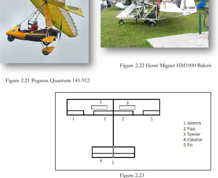
The most common way to control an airplane is to have a pair of ailerons, a rudder and an elevator. Bigger airplanes often have a couple of spoilers on the wings as well. As a last resort it‟s also possible to control an airplane with its engine(s). Some airplanes control their way through the air by moving the center of gravity in relation to the wing, usually a Rogallo wing. This kind of wing is shown in the picture below on a Pegasus Quantum1. On the flying flea (which is a
tandem wing aircraft) the angle of incidence was variable to be able to use the whole wing as an elevator (the picture to the right is showing a HM1000 Balerit2, which is based on the same
concept as the flying flea).
1 http://en.wikipedia.org/wiki/File:Pegasus_quantum_15-912_microlight_g-byff_kemble_arp.jpg 2010-08-08 2 http://en.wikipedia.org/wiki/File:AvionsHenriMignetHM1000Balerit03.JPG 2010-08-08
Figure 2.21 Pegasus Quantum 145-912
Figure 2.22 Henri Mignet HM1000 Balerit
Possible flight controls set up for a Z-wing Ailerons and elevator(s)
To start with, a regular airplane do get some unwanted moments when deflecting a control surface which can cause problems. But these secondary effects are very small in comparison both to the primary effect and to the Z-wing configuration. For a Z-wing on the other hand, there are some unwanted moments that will arise with e.g. an aileron deflection.
As drawn and shown at the picture below the forces created by the ailerons is forming a force couple. Not only does the force couple create a moment about the longitudinal axis, which we want, but it also creates an unwanted moment about the pitch axis.
Since there is no horizontal stabilizer (in this case), the pitch control will have to be placed at the wings. Enebog made the suggestion that the elevators should be placed as close as possible to the longitudinal axis to minimize the unwanted roll moment the elevators would create at deflection.
To minimize the pitch moment created by the deflecting ailerons, Gustaf Enebog also come up with the idea that the front wing could be swept backward and the aft wing could be swept forward. This sweeping of the wings would make the arm between the force couple smaller along the longitudinal axis; maybe even cancel them out completely with enough sweeping.
When the sweep of the wings was calculated, several things were considered. First of all, the wings aerodynamic centre with regard of the ailerons shall be lined up. With that in mind, it must be decided where and how they shall line up. To be able to explain this part it has to be told that the final version of the straight winged Z-wing ended up with a front wing half span of 1.5 meters and aft wing half span of 1.3125 meters. The wings can be swept in several different ways. They can be swept with a constant wing span or they can be swept with a constant distance between the root and the tip of the wing. Because the wings does not have the same wing span it had to be decided if the wings were going to line up at a specific point, which would make the wings have ha different amount of sweep, except at one point, or if the wings should have the same sweep and let the wings line up at the previously mentioned point.
The Ailerons was said to be placed at the outer third of the wing span. The centre of this outer third will then have its position at 5/6 of the half span. It was decided that the wing span should be kept constant during the sweep since the lift otherwise probably would decrease too much. After that, it was decided that the wings should be swept by the same angle. The formulas for those calculations are shown on the next page:
Figure 2.25
𝐵 =5
6(𝐻𝑎𝑙𝑓 𝑠𝑝𝑎𝑛 𝑜𝑓 𝑓𝑟𝑜𝑛𝑡 𝑤𝑖𝑛𝑔) ∙ tan(𝜃)
𝐶 =5
6(𝐻𝑎𝑙𝑓 𝑠𝑝𝑎𝑛 𝑜𝑓 𝑎𝑓𝑡 𝑤𝑖𝑛𝑔) ∙ tan(𝜃) 𝐴 = 𝐵 + 𝐶
These equations end up to:
𝐴 =5
6 𝑆𝑝𝑎𝑛 𝑜𝑓 𝑓𝑟𝑜𝑛𝑡 𝑤𝑖𝑛𝑔 + (𝑆𝑝𝑎𝑛 𝑜𝑓 𝑎𝑓𝑡 𝑤𝑖𝑛𝑔) ∙ tan 𝜃 A, the half span of the front wing and the half span of the aft wing is known. So:
𝜃 = 𝑡𝑎𝑛−1 𝐴
5
6 𝑎𝑙𝑓 𝑠𝑝𝑎𝑛 𝑜𝑓 𝑓𝑟𝑜𝑛𝑡 𝑤𝑖𝑛𝑔 + (𝐻𝑎𝑙𝑓 𝑠𝑝𝑎𝑛 𝑜𝑓 𝑎𝑓𝑡 𝑤𝑖𝑛𝑔)
Fin and rudder
Type of fin and rudder
Because the z-wing creates moments about all the three axes it gets very difficult to cancel these moments out by only changing the variables of the two wings. The z-wing would probably need another, third, wing, a fin.
This fin could be in many different shapes, the picture below shows two main ideas. The asymmetrical T-tail and the tilted fin (the asymmetrical T-tail obviously makes it a four wing surfaces in total).
A regular fin might do the job needed to help cancelling out the moments as mentioned before, but to control the wing there‟s another aspect to the extra fin. When controlling the z-wing it might be useful to be able to counteract the extra moments created by the different rudders and a regular fin maybe isn‟t enough, maybe the fin have to be able to create moments in both about yaw and pitch.
So, the picture shows four different tail solutions and the T-tail and the fin is really just there to show the morphology of the Asymmetric T-tail and the Tilted fin. The regular T-tail could
Equation 2.27
absolutely be a solution for the Z-wing as well, but since the Z-wing is asymmetric from the beginning an asymmetric tail section would be more suitable for the project as much as it would look cool. The T-tail would also add more weight to the airplane (assuming the reinforcement that probably will have to be made weighs less than the extra wing).
Both the Asymmetric T-tail and the Tilted fin have its drawbacks and benefits. For a start, the Tilted fin only consists of one wing surface while the Asymmetric T-tail got two. But on the other hand, the Asymmetric T-tail can vary the moments about yaw and pitch separately while the Tilted fin varies the both when deflecting its rudder. Both solutions have the drawback of an extra, unwanted, moment about the longitudinal axis when deflecting the rudder to create a pitch moment (an unwanted moment the T-tail wouldn‟t get).
Position of fin and rudder
The tail section could be placed at several places with different benefits and drawbacks. The biggest thing to decide is if the fin should work as a winglet for the aft wing and thereby make the aft wing create more lift (and thereby make the difference in lift between the wings a little smaller) or place the fin as far back as possible to increase the arm to the center of gravity.
2.6 Lift/drag optimization
Fuselage thickness
As you know, there are many ways to optimize to the lift and the drag. One way, which was mentioned under the title “Position of fin and rudder”, is to add winglets. But the Z-wing not only got outer wingtips, it also got inner wingtips. This fact raised the matter of how much the size of the fuselage affected the induced drag at the inner wingtips, since the fuselage is working as a winglet in a perspective.
A small analysis of this was made in Tornado. The wings in these analyses were treated in two different ways. In one analysis the Z-wings had the same wing span regardless of the size of the fuselage which means that the wing area decreased as the fuselage got bigger. In the other analysis the wing was kept in its original shape and the wings were moved outwards as the fuselage got bigger.
2.7 Landing gear configuration
An airplane is demanding a few things of its landing gears. For instance a stable ground handling is often needed and the placement of the landing gear should not make either the ground roll or landing difficult.
For the ground roll, it‟s seen on the figure that the distance between the center of gravity and the main landing gear is important. The moment from the wings that will pitch the nose up at ground roll have to overcome the moment from the weight and the distance between the center of gravity and the main landing gear. When that solution is solved the most aft position for the main landing gear is decided. The most forward position of the landing gear is decided by the angle “a” also seen in the figure below. If this angle is too small the airplane will be vulnerable to tail strikes.
Since the center of gravity and the wings are more separated than on a conventional airplane, the main landing gear might not end up nicely right under the wings as it often does. Probably, they will end up mounted between the aft wing and the center of gravity, as seen in the previous figure.
The perspective of this thesis is a small UAV; it could therefore be assumed that the weight of the aircraft will not put huge demands of the landing gears, which opens up for a solution without any advanced shock absorbers and the possibility of having body mounted landing gears.
The airplane will probably not fly fast enough for having a strong demand for retractable landing gears. An advantage with the fixed landing gear is, except for simplicity, that it will give the aircraft a pitch moment that will counteract the pitch moment created by the wings and thereby the counteracting moments could be decreased.
The problem the Z-wing has with its landing gear configuration is the asymmetric wings. As well as when the airplane is flying, the fuselage is going to have a twisting moment over it when on ground. The positive aspect is that the moment over the fuselage will be less when on ground than it will be in air; assuming most of the weight is placed in the fuselage. If this is the truth, a landing gear configuration with its landing gears mounted on the fuselage will not be a concern to the moment.
Another problem that has to be dealt with is the strange weight distribution. With a big mass placed at front right and another mass at the aft left the airplane will probably have a tendency to tip at strong decelerations. But again, since the purpose of this thesis is a small UAV the airplane are less likely to have a strong demand for a heavy deceleration and a configuration with one nose wheel and two main wheels will probably do the job. But the main landing gears will probably have to be quite wide, comparing to regular landing gear configurations. No calculations have been done for the landing gears and this section is therefore left outside the results.
2.8 The Z-wings applicability
An analysis was made around the applicability of the Z-wing configuration. Could it be possible to have a big airplane flying with a Z-wing configuration? Some quick and simple calculations were made for a couple of existing airplanes to calculate the bending moments that the fuselages will be exposed for when the wings are placed in a Z-wing configuration. For simplicity the all airplanes was assumed to have straight wings and the lift were calculated to act at the centre of the wings at 50% of the chord. The drag was also set to 10% of the lift.
Chapter 3
RESULTS / DISCUSSION
3.1 Different parameters contribution to moments
These analyses were made as a part for the research of the Z-wing characteristics, but it also functioned as tools for trying to cancel out the moments around the Z-wing. Remember these values and graphs do not have its origin from a trimmed state of flight.
Changing the angle of incidence of the wings
The research tried out three different angles of incidences; -3, 0 and 3 degrees. In the graphs the corresponding difference in moment is seen. The tables which the graphs are based on are placed in annex A. -100 -50 0 50 100 150 -4 -2 0 2 4 Momen t % Angle of incidence
Yaw moment
Front wing Aft wing Fin Stabilizator -300 -200 -100 0 100 200 300 400 -4 -2 0 2 4 Momen t % Angle of incidenceRoll moment
Front wing Aft wing Fin Stabilizator Figure 3.1 Figure 3.2-50 -40 -30 -20 -10 0 10 -30 -20 -10 0 10 20 30 Momen t % Wing area %
Yaw
Front wing Aft wingThe graphs are pretty self explanatory; the more gradient at a curve, the more it will affect that specific moment when varying the angle of incidence.
Changing the size of the wings
The areas of the wings were varied by varying the wingspan with a constant length of the chord. The tables which the graphs are based on are placed in annex B. As seen in the graphs, the area was changed with 10% and 20%.
-60 -40 -20 0 20 40 60 -4 -2 0 2 4 Momen t % Angle of incidence
Pitch moment
Front wing Aft wing Fin Stabilizator -300 -200 -100 0 100 200 300 400 -30Momen -20 -10 0 10 20 30 t % Wing area %Roll
Front wing Aft wing Figure 3.3 Figure 3.4 Figure 3.5
As well as the graphs for the angle of incidence against the specific moments, a bigger gradient is synonymous with a greater influence at the specific moment. With that explained the graphs are easy to understand. However, one interesting thing is showing at the graph displaying the yaw moment. The yaw moment is going to decrease as the aft wing area is increasing as well as it does when the same area is decreasing. First of all, it has to be remembered that the configuration is not in trimmed state at the origin. With that stated the graph shows that a decrease in wing area will decrease the wing and thereby decrease the cause of the yaw moment. An increase in the wing area, on the other hand, will decrease the yaw moment because the wing is creating more drag and thereby a bigger force to counteract the original moment. When the wing becomes big enough it will create a moment in the opposite direction.
Changing the dihedral of the wings
The graph of the relationship between Cn and dihedral can be seen in the graph on the next page, as well as the difference in percentage between Tornados result and the calculated model at dihedrals between -30 and 30 degrees. The table with values and the difference between the model and Tornado‟s results for dihedrals between -90 and 90 degrees can be seen in Annex C. The formula for the relationship can be seen under here where ∅ is the angle of dihedral in degrees. 𝐶𝑛 = 0.0537815 × sin 36∅ 13 − 0.091954 -30 -20 -10 0 10 20 -30 -20 -10 0 10 20 30 Momen t % Wing area %
Pitch
Front wing Aft wing Figure 3.6 Equation 3.7The difference in the curves and the reason for the curve not passing through the origin of the graph is that the wing configuration is not in trimmed state around the normal axis. The wing configuration is also including a fin for this curve, which is also affecting the yaw moment.
A negative Cn does in this curve mean a clockwise yaw moment, when observing the
Z-wing from above. This clockwise yaw moment exist due to the difference in lift of the two Z-wings, with the aft wing producing more lift than the front wing.
At small angles of dihedral the increased lift from the aft wing is probably caused because the right vortex from the front wing is decreasing the vortex from the left side of the aft wing. At higher angels of dihedral the way moment seems to increase with an increasing rate. This is probably caused by the downwash from the front wing, creating a higher angle of attack on the aft wing and thereby increasing the lift.
-15 -10 -5 0 5 10 -30% -20 -10 0 10 20 30 Degrees of dihedral
Difference in yaw moment coefficient, % vs.
Dihedral, degrees
Difference in % -0,5 -0,4 -0,3 -0,2 -0,1 0 0,1 0,2 -100 -50 0 50 100 Cn Degrees of dihedralYaw moment coefficient, Cn vs. Dihedral
Tornado Formula
Figure 3.8
-12 -10 -8 -6 -4 -2 0 0 2 4 6 8 Roll mom ent, Nm x/chord
Roll moment vs. longitudinal
displacement
Roll moment vs. longitudinal displacement Changing the placement of the wings
The graphs here are calculated in Tornado and is using the two “sliding” morphologies as explained in the pictures. The figures that the graphs are based on from Tornado are attached in Annex D. The „x‟ stands for the displacement of the wing. Everything except the placement of the two wing surfaces is fixed values.
Longitudinal displacement
These graphs and pictures below are for the longitudinal displacement. They are quite self-explanatory but are discussed after the last graph.
Figure 3.10
-600 -500 -400 -300 -200 -100 0 0 2 4 6 8 Pi tc h m om en t, Nm x/chord
Pitch moment vs. longitudinal
displacement
Pitch moment vs. longitudinal displacement -1,2 -1 -0,8 -0,6 -0,4 -0,2 0 0,2 0 2 4 6 8 Yaw mom ent, Nm x/chordYaw moment vs. longitudinal
displacement
Yaw moment vs. longitudinal displacement 320 330 340 350 360 370 380 390 400 0 2 4 6 8 Lif t, N x/chordLift vs. longitudinal displacement
Lift vs. longitudinal displacement Figure 3.12
Figure 3.13
The graphs clearly show that different moment is arising when transforming a regular wing to a Z-wing. The roll moment, as well as the yaw moment, is increasing until the wing displacement is about 3 times the chord length, then it starts to reduce.
The pitch moment is increasing linearly and the lift is decreasing the more aft the wing is moved. Remember also that it‟s only the wing that is moved, nothing more is done with the wing. This means that the aft wing is working in dirty air and its angle of incidence is not corrected to make the wing work at a constant angle of attack, which could be done by changing the angle of incidence as the wing is moved.
Lateral displacement
These graphs and pictures are for the lateral displacement and are, as for the longitudinal displacement, self-explanatory but are commented after the last graph.
0 50 100 150 200 250 0 0,5 1 1,5 Roll mom ent, Nm x/half span
Roll moment vs. lateral displacement
Roll moment vs. lateral displacement Figure 3.15
-350 -300 -250 -200 -150 -100 -50 0 0 0,5 1 1,5 Pi tc h m om en t, Nm x/half span
Pitch moment vs. lateral
displacement
Pitch moment vs. lateral displacement 0 1 2 3 4 5 6 7 8 0 0,5 1 1,5 Yaw mom ent, Nm x/half spanYaw moment vs. lateral displacement
Yaw moment vs. lateral displacement 0 50 100 150 200 250 300 350 400 0 0,2 0,4 0,6 0,8 1 1,2 Lif t, N x/half span
Lift vs. lateral displacement
Lift vs. lateral displacement Figure 3.17
Figure 3.18
Logically, the more the wings are separated in lateral axis, the stronger the moments get. It‟s clearly seen that the total lift increases when the wing gets out of the dirty air behind of the front wing,
Vertical displacement – Z-wing
The wings were also moved in vertical axis. Since the aft wing is traveling in the dirty air behind the front wing, a change in vertical separation between the two will change both the total moments and the lift created. How the moments and lift are related to the vertical displacement at the Z-wing was mapped out in Tornado. In the next four graphs the result is seen. The horizontal axis describes the quote between the displacement and the chord length.
195 200 205 210 215 220 225 230 -1,5 -1 -0,5 0 0,5 1 1,5 Roll mom ent, Nm x/chord
Roll moment vs. vertical
displacement
Roll moment vs. lateral displacement 0 1 2 3 4 5 6 7 8 -1,5 -1 -0,5 0 0,5 1 1,5 Yaw mom ent, Nm x/chordYaw moment vs. vertical
displacement
Yaw moment vs. vertical displacement Figure 3.20
The graphs clearly show that there is a breakpoint when the quote is about 0.25. This has to do with a combination of the down wash from the front wing and the vortex from the front wing cancelling out a bit of the vortex from the aft wing. This is looked into a little bit further under title 3.6 “Lift/Drag optimization”.
-340 -330 -320 -310 -300 -290 -280 -1,5 -1 -0,5 0 0,5 1 1,5 Pitch mom ent, Nm x/chord
Pitch moment vs. vertical
displacement
Pitch moment vs. vertical displacement 310 315 320 325 330 335 340 -1,5 -1 -0,5 0 0,5 1 1,5 Lif t, N x/chordLift vs. vertical displacement
Lift vs. vertical displacement Figure 3.22
Vertical displacement – Tandem wing
For a comparison, the same graphs were made with a tandem wing. The roll and yaw moment did not, as expected, vary significantly much and therefore these graph was left outside this report.
These graphs show the same interesting fact, a breakpoint when the quote is 0.25. -250 -200 -150 -100 -50 0 -1,5 -1 -0,5 0 0,5 1 1,5 Pitch mom ent, Nm x/chord
Pitch moment vs. vertical
displacement
Pitch moment vs. vertical displacement 0 50 100 150 200 250 300 -1,5 -1 -0,5 0 0,5 1 1,5 Lif t, N x/chordLift vs. vertical displacement
Lift vs. vertical displacement Figure 3.24
3.2 The configuration for a steady level flight
The original model for this part of the thesis was, as with many other analyses in this thesis, the basic Z-wing described in title 2.1 was used. This basic Z-wing also stood as a model from which the steady flying Z-wing shouldn‟t differ too much. As stated before in methods; this part was very much about trial and error. But the workload was reduced after having the couplings between the different parameters and their contribution to different moments mapped out.
This final version of the straight winged Z-wing-configuration actually had some moments over it, but the unwanted moments had been significantly reduced. At this particular set up of the parameters it was decided that a more precise parameter-set-up had been more of a waste of time instead of being informational. The graph below describes the different moments and forces over the Z-wing changes over some of the computations made in Tornado. The drag of the configuration did not vary significantly and was therefore left outside this graph.
The parameters of the steady flight level Z-wing are these:
Parameter Front wing Aft wing Fin Stabilizer
Profile NACA 2412 NACA 2412 NACA 0009 NACA 0009
Half span 1.5 m 1.3125 m 0.5 m 0.64 m Chord length 0.4 m 0.4 m 0.4 m 0.4 m Angle of incidence -2ᵒ -2ᵒ -2ᵒ -7ᵒ Longitudinal placement 0 m 1.5 m 4.5 m 4.5 m Vertical placement 0 m 0.3 m 0.3 m 0.8 m Lateral placement 0 m 0 m 0 m 0 m -400 -300 -200 -100 0 100 200 300 400 1 3 5 7 9 11 13 15 17 19 21 23 25 27 29 31 33 35 37 39 41 43 45 47 49 [N] / [Nm] Run no.
Forces acting on Z-wing vs. computer runs
Lift [N] Roll [Nm] Pitch [Nm] Yaw [Nm] Figure 3.26 Table 3.27
These figures show the output from Tornado. Figure 3.28 shows the configuration and the delta cp distribution. Figure 3.29 shows the forces, moments and coefficients over the Z-wing.
Figure 3.28
As seen in the graph named “Forces acting on Z-wing vs. computer runs” before the last page, showing the change of the forces and moments during different computer runs towards a steady level flight. The lift decreases from about 340 N to about 190 N. This means that the lift is decreased by almost 45% from its basic parameter setting to get the Z-wing configuration in a steady flight. This fact has been monitored during the analysis and the wings span has been increased in a try to minimize the decrease in lift.
This Z-wing configuration has a wing span of less than 3 meter, a length of 5 meters and a lift force of 190 Newton. This means that if this Z-wing airplane will fly it have to be built from a very light weight and strong material, if even that is enough.
The fin which is used for this flight state is an asymmetric or half T-tail. As explained earlier this type of fin was chosen in the tries to get the Z-wing to fly a steady level flight because it made the whole operation much easier. Now a functioning solution for the tail section is existing and this would able a tilted fin solution to be find.
The advantages of a tilted fin over a half T-tail is primary a much simpler airflow and less drag. As mentioned in methods, a tilted fin would also make the Z-wing look much better. The big disadvantage is, of course, the different forces that would appear when trying to use the ruddervator (a combined rudder and elevator), since a ruddervator deflection would give rise to moment and forces in pitch, roll and yaw at the same time. This would be a problem for the half T-tail as well, but the T-tail can combine ailerons, rudder and elevator to correct the unwanted moments. The tilted fin has only the ruddervator and the ailerons to use for the same purpose.
Also remember that this configuration is valid only for this particular air speed. A change in speed would change the CL and change the CD. These changes would in turn change all the
moments around the airplane and force the use of control surfaces for counteraction. The control surfaces do, in their turn, also change the moments in their particular way and here things are getting complicated. This is leading to the next title.
3.3 Controlling the Z-wing
When a steady flight with the Z-wing was established, it was time to discover how the different control surfaces affected the Z-wing. The analysis was done for control surfaces angles between -5ᵒ and +5ᵒ. The size of the ailerons was put to a third of the half span and 35% of the chord length. The outcome of this analysis is seen graphs below and the tables with the values are seen in Annex E Drag has been removed from the graphs since they stay nearly constant.
. -200 -150 -100 -50 0 50 100 150 200 250 -10 -5 0 5 10 [N] /[Nm] Degrees deflection
Yaw - Rudder
Lift [N] Roll [Nm] Pitch [Nm] Yaw [Nm] -250 -200 -150 -100 -50 0 50 100 150 200 250 300 -10[N] -5 0 5 10 /[Nm] Degrees deflectionPitch - Elevator
Lift [N] Roll [Nm] Pitch [Nm] Yaw [Nm] Figure 3.30 Figure 3.31-100 -50 0 50 100 150 200 250 -6 -4 -2 0 2 4 6 [N] /[Nm] Degrees deflection
Roll - Right Aileron
Lift [N] Roll [Nm] Pitch [Nm] Yaw [Nm] -100 -50 0 50 100 150 200 250 -6 -4 -2 0 2 4 6 [N] /[Nm] Degrees deflection
Roll - Left Aileron
Lift [N] Roll [Nm] Pitch [Nm] Yaw [Nm] Figure 3.32 Figure 3.33
The graphs clearly shows that almost all control deflections create moments about all of the Z-wings axes. This will be a problem if someone is going to try controlling the Z-wing. One way to solve this problem is to try combining different control surfaces in an effort to cancel out the unwanted moments. Another way is to place the control surfaces in different places to minimize the unwanted moments. But this problem is actually beyond the purpose of this thesis and will therefore be left unanswered. But at least most of the unwanted pitch moment due to aileron deflection can be minimized by sweeping the wings, which will be done under the next title.
3.4 Sweeping the wings
As previously mentioned, a sweepback of the front wing and a forward sweep of the aft wing were made to minimize the unwanted moments. The sweep angle was decided by equation 2.27. 𝜃 = 𝑡𝑎𝑛−1 𝐴 5 6 𝑎𝑙𝑓 𝑠𝑝𝑎𝑛 𝑜𝑓 𝑓𝑟𝑜𝑛𝑡 𝑤𝑖𝑛𝑔 + (𝐻𝑎𝑙𝑓 𝑠𝑝𝑎𝑛 𝑜𝑓 𝑎𝑓𝑡 𝑤𝑖𝑛𝑔) 𝜃 = 𝑡𝑎𝑛−1 1,5 5 6 1,5 + (1,3125) = 32,62ᵒ -100 -50 0 50 100 150 200 250 -6 -4 -2 0 2 4 6 [N] /[Nm]
Roll to the left - Degrees deflection - Roll to the right
Roll - Both ailerons
Lift [N] Roll [Nm] Pitch [Nm] Yaw [Nm]
The Z-wing configuration then looks like this with 32.62ᵒ of sweep:
Figure 3.35
The change of the moments only due to the sweep is shown in the graphs below. -6 -4 -2 0 2 4 6 8 10 12 14 0 10 20 30 40 [Nm] Sweep angle
Sweep angle
Roll [Nm] Pitch [Nm] Yaw [Nm] 0 20 40 60 80 100 120 140 160 180 200 0 10 20 30 40 [N] Sweep angleSweep angle
Lift [N] Drag [N] L/D 47,5 48 48,5 49 49,5 50 0 10 20 30 40 [Nm] Sweep angleSweep angle vs. L/D
L/D Figure 3.37 Figure 3.38 Figure 3.39The graph below shows the moments and forces upon the Z-wing with its wings swept and both its ailerons deflecting.
This graph clearly shows that the unwanted moments decrease with this particular wing settings. It is also seen that the sweep wasn‟t completely successful, since the use of the ailerons still creates a moment in pitch. But in the other hand, it‟s not only the airflow around the ailerons that is going to be affected by the surface deflection, the lift from the whole wing is going to change and they are, still, placed in asymmetric positions.
All of the tables that these graphs are based on are placed in Annex F.
3.5 Beta angles for swept and straight wing configuration
Computer runs for different Beta angles were made in Tornado for both the swept and straight winged Z-wing configuration. As expected, the moment coefficients changed quite a lot when changing the amount of side slip. The results are for angles between -10ᵒ and +10ᵒ and can be seen on the next page. The straight and swept winged Z-wing behaves quite similar to the beta angle. The biggest difference is seen in the CL/Beta-graph.
-100 -50 0 50 100 150 200 -6 -4 -2 0 2 4 6 [N] / [Nm] Rudder angel
Swept wings - Roll
Lift [N] Roll [Nm] Pitch [Nm] Yaw [Nm]
Results for the straight winged Z-wing.
Results for the swept Z-wing.
Figure 3.41
3.6 Lift/Drag optimization
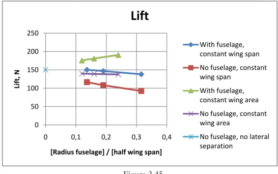
As stated before, an analysis of how the body affected the induced drag and thereby the lift was done. The graphs on the next page show the results. These results are also shown in tables in Annex G. The difference in these different graphs is found in the axes; in one graph the axis describes the radius of the fuselage contra the lift while the second graph is treating the ratio between the radius of the fuselage and the span of one wing contra the lift. The last graph treats the ratio between the radius of the fuselage and the span of one wing contra the lift created per square meter, the reason for the two last graphs is to normalize the curves.
0 50 100 150 200 250 0 0,1 0,2 0,3 0,4 Lif t / Wing ar ea, N/m 2
[Radius fuselage] / [half wing span]
Lift
With fuselage, constant wing span No fuselage, constant wing span
With fuselage, constant wing area No fuselage, constant wing area No fuselage, no lateral separation 0 50 100 150 200 250 0 0,1 0,2 0,3 0,4 Lif t, N Radius fuselage, m
Lift
With fuselage, constant wing span No fuselage, constant wing spanWith fuselage, constant wing area No fuselage, constant wing area No fuselage, no lateral separation Figure 3.43 Figure 3.44
The curves in these graphs don‟t come as a surprise even though the numbers are interesting. The larger the radius of the fuselage is, the more lift are being created by the wings. An interesting output from these graphs is that the Z-wing creates more lift when the inner wingtips align with each other compared to the situation when they are separated. A small research was done of this and can be seen here below.
The distance from the origin to the different circles represents the amount of lift and drag in Newton that are created. The numbers at the outer circle represents how the aft wing is displaced. The first number represents how much the aft wing is displaced along lateral axis in meters. If the number is negative, the wings are overlapping and if the number is positive the front and aft wing have a gap between the inner wing tips. The second number represents how the aft wing is displaced along the normal axis. A negative number means that the wing is placed below the front wing and a positive number means that the aft wing is placed higher than the front wing. A table, from which the graphs are made from, is placed in Annex H.
0 50 100 150 200 250 0 0,1 0,2 0,3 0,4 Lif t, N
[Radius fuselage] / [half wing span]
Lift
With fuselage, constant wing span No fuselage, constant wing span
With fuselage, constant wing area No fuselage, constant wing area No fuselage, no lateral separation 290 300 310 320 330 340 350 3600 / 0 0 / 0.3 0.1 / -0.3 0.1 / -0.1 0.1 / 0 0.1 / 0.1 0.1 / 0.3 0.3 / -0.3 0.3 / 0 0.3 / 0.3 -0.3 / -0.3 -0.3 / 0 -0.3 / 0.3 0 / -0.3
Lift vs placement of inner wing tip
Lift vs placement of inner wing tip
Figure 3.46 Figure 3.45
The graphs show that most lift is created when the tips are having a little gap between each other. This is probably due to a combination of the down sweep from the front wing and the vortex of the front wing cancelling out some of the vortex being created at the aft wing. On the next page a graph showing the drag for the same conditions are presented and there it‟s seen that the lowest value of drag occurs when the wings are having a small gap and the wings are kept level to each other.
7 7 8 8 9 90 / 0 0 / 0.3 0.1 / -0.3 0.1 / -0.1 0.1 / 0 0.1 / 0.1 0.1 / 0.3 0.3 / -0.3 0.3 / 0 0.3 / 0.3 -0.3 / -0.3 -0.3 / 0 -0.3 / 0.3 0 / -0.3
Drag vs placement of the aft inner wing tip
Drag vs placement of inner wing tip
3.7 The Z-wings applicability
This thesis around the Z-wing has been made with the thought of being applied on a UAV, but can it be possible to put the Z-wing configuration on a bigger aircraft? After some calculations the thought of having a Z-wing configuration applied on anything bigger than a UAV is far away. Even a UAV can be tough to build, but with
The table uses the same wing area, wing span, length and weight as the airplane types for a simple comparison and an easy calculation of the bending moments at the fuselage. For the moment about the longitudinal axis it is also assumed that the front wing is mounted at the front, the aft wing is mounted all the way in the back and that both wings produce the same amount of lift. The lift is calculated, for simplicity, to act at 50% of the cord. The drag is estimated to 10% of lift. Airplane type MTOW (kg) Length (m) Lift/wing (N) Wings pan (m) Moment at fuselage around the longitudinal axis (kNm) Moment at fuselage around the vertical axis (kNm) Moment at fuselage around the lateral axis (kNm) UAV 50 2 245.5 1.5 0.36825 0.036825 0.491 C172R 1157 8.2 5680.87 11 62.48957 6.248957 46.583134 Cessna Citation 6800 14.39 33388 15.91 531.20308 53.120308 480.45332 Saab 2000 22800 27.28 111948 24.76 2771.83248 277.183248 3053.94144 B737-800 79015 39.47 387963.6 5 34.31 13311.03283 1331.103283 15312.9252 7 B747-400 412770 70.67 2026700. 7 64.44 130600.5931 13060.05931 143226.938 5 A380-800 560000 72.75 2749600 79.8 219418.08 21941.808 200033.4
This table clearly shows that the Z-wing configuration will probably only be applicable for smaller UAV‟s, and even for that propose the airplane will be putting a lot of demands on the material used. It will need some strong, light materials and a clever weight distribution to make it possible. Perhaps the fuselage can be built of a carbon fiber tubing similar to drive shafts used in car racing.
Chapter 4
CONCLUSIONS
4.1 Conclusions from the analysis of the Z-wing
From the very beginning of the work with this thesis, the Z-wing seemed like a very complex type of wing configuration and this thesis have definitely showed this.
The thesis has also showed that a straight and level flight is achievable with a Z-wing configuration, even though it brings many problems. For this configuration and size of airplane (UAV) the lift force were reduced to about 55% of its original value in an untrimmed state. That is a huge loss in lift. Besides that, controlling the Z-wing will be a small project for itself. With the front wing swept backwards and the front wing being swept forwards most of the unwanted pitch moment due to roll control is lost. But the tail solution, either with a tilted fin or the solution in this thesis, an asymmetric T-tail, will complicate at least control in pitch.
For the question if a vertical/horizontal fin/stabilizer is necessary for a trimmed flight, this thesis really don‟t bring an answer. The different tries that have been done here shows that it is very hard to find a trimmed state without a fin or a stabilizer, but they haven‟t showed that it would be impossible.
If it‟s assumed that all problems with the controlling of the Z-wing are getting solved, which they probably can be, the fuselage of the airplane still would have to withstand a huge amount of torque. For example a simplified calculation showed that the fuselage would have about 370 Nm of torque along the longitudinal axis, for a Z-wing weighing 50 kg.
But the Z-wing has to be lighter than that, the configuration that achieved straight and level flight had a lift of about 190 N, with a total wingspan of 2.8125 meters and a length of 5 meters. So, it‟s crucial that the Z-wing configured UAV is made of lightweight and very strong material. The fuselage would preferably be made of some kind of carbon fiber tubing.
With all that said, not much speaks for the Z-wing configurations advantage. But the Z-wing will always look odd, it will always look strange and if people look at a flying Z-wing they will probably say “It‟s amazing that thing can fly”. For that purpose, it will always be worth the effort to get one flying.
Chapter 5
REFERENCES
____________________________________
1. Gustaf Enebog, Informal thoughts on the z wing concept Enebog, 2008
2. Anderson, John D. Jr., Fundamentals of Aerodynamics, 4th Edition, McGraw Hill, New York, 2007, ISBN 007-125408-0
A. ANNEX
Annex A is showing tables with data regarding the connection between angle of incidence and moments/forces.
Angle of incidence Forces
Front wing Aft wing Fin stabilizer Lift [N] Drag [N] Roll [Nm] Pitch [Nm] Yaw [Nm]
0 0 0 0 339 6.6 18.2 -355.7 -99.6 -3 0 0 0 250 3.4 -27.7 -344.6 -113.7 0 -3 0 0 250 5.9 69.5 -212.9 -95.4 0 0 -3 0 329 6.9 2.2 -329 -32 0 0 0 -3 320 6.1 9 -305.5 -74.7 3 0 0 0 427 12.6 64.4 -366 -88 0 3 0 0 372 9.1 -8.4 -407.2 -102.3 0 0 3 0 393 12 45.6 -499.2 -196.9 0 0 0 3 360 8.1 37.1 -408.7 -162.4 ROLL, %
Angle of incidence Front wing Aft wing Fin stabilizer
-3 -252.198 281.8681 -87.9121 -50.5495
0 0 0 0 0
3 253.8462 -146.154 150.5495 103.8462
PITCH, %
Angle of incidence Front wing Aft wing Fin stabilizer
-3 -3.12061 -40.1462 -7.50633 -14.113
0 0 0 0 0
3 2.895699 14.47849 40.34299 14.9002
YAW, %
Angle of incidence Front wing Aft wing Fin stabilizer
-3 14.15663 -4.21687 -67.8715 -25
0 0 0 0 0
B. ANNEX
Annex B is showing tables with data regarding the connection between wing area and moments/forces.
Wing Area [%] Forces
Front wing Aft wing Lift [N] Drag [N] Roll [Nm] Pitch [Nm] Yaw [Nm]
0 0 339 6.6 18.2 -355.7 -99.6 20% 0 387 7.2 69.5 -364.7 -96.2 10% 0 363 6.9 42.3 -360.2 -97.9 -10% 0 316 6.3 -2.5 -351.3 -101.4 -20% 0 295 5.9 -20.1 -347.1 -103.4 0 20% 379 9.9 9.4 -416.2 -79.2 0 10% 361 9.3 13.1 -388.8 -91.2 0 -10% 313 9 19.1 -310 -72.6 0 -20% 288 8.7 24.7 -267.4 -59.3 ROLL, %
Wing area, % Front wing Aft wing -20 -210.44 35.71429 -10 -113.736 4.945055 0 0 0 10 132.4176 -28.022 20 281.8681 -48.3516 PITCH, %
Wing area, % Front wing Aft wing -20 -2.41777 -24.8243 -10 -1.237 -12.8479 0 0 0 10 1.265111 9.305595 20 2.530222 17.00872 YAW, %
Wing area, % Front wing Aft wing -20 3.815261 -40.4618 -10 1.807229 -27.1084
0 0 0
10 -1.70683 -8.43373 20 -3.41365 -20.4819
C. ANNEX
Annex C is showing the table with data regarding the connection between dihedral and Cn. It is also showing the whole graph of the difference between the mathematical model
and Tornados calculated Cn. The equation used for the model is as well written here.
𝐶𝑛 = 0.0537815 × sin 36∅
13 − 0.091954
Angel ᵒ Cn, Tornado Cn, Formula Difference Difference, %
-90 0.13775 -0.04167 0.179417 130.2486 -85 0.069859 -0.04769 0.117552 168.2699 -80 0.055069 -0.05629 0.111359 202.2177 -75 0.032276 -0.06696 0.099236 307.4622 -70 0.0069325 -0.07908 0.086016 1240.761 -65 -0.018469 -0.09195 0.073485 -397.883 -60 -0.042555 -0.10482 0.06227 -146.328 -55 -0.064451 -0.11695 0.052497 -81.4518 -50 -0.083548 -0.12762 0.04407 -52.7478 -45 -0.099418 -0.13622 0.036797 -37.0127 -40 -0.11178 -0.14224 0.030461 -27.2505 -35 -0.12049 -0.14534 0.024853 -20.6269 -30 -0.12552 -0.14534 0.019823 -15.793 -25 -0.12699 -0.14224 0.015251 -12.0093 -20 -0.1251 -0.13622 0.011115 -8.88514 -15 -0.1202 -0.12762 0.007418 -6.17116 -10 -0.11269 -0.11695 0.004258 -3.77807 -5 -0.10309 -0.10482 0.001735 -1.68276 -3 -0.098787 -0.09972 0.000938 -0.94935 -2.5 -0.097677 -0.09844 0.00076 -0.77771 -2 -0.096555 -0.09714 0.00059 -0.6107 -1.5 -0.09542 -0.09585 0.00043 -0.45027 -1 -0.094276 -0.09455 0.000276 -0.29315 -0.5 -0.09312 -0.09325 0.000134 -0.14343 0 -0.091954 -0.09195 0 0 0.5 -0.090778 -0.09065 -0.00012 0.136115 1 -0.089594 -0.08936 -0.00024 0.266051 1.5 -0.088403 -0.08806 -0.00034 0.389865 2 -0.087203 -0.08676 -0.00044 0.504184 2.5 -0.085998 -0.08547 -0.00053 0.61239 3 -0.084786 -0.08418 -0.0006 0.711011 5 -0.079888 -0.07908 -0.0008 1.007355 10 -0.06752 -0.06696 -0.00056 0.828657