BACHELOR THESIS IN
AERONAUTICAL ENGINEERING
15 CREDITS, BASIC LEVEL 300
School of
Innovation
, Design and Engineering
SIMULATION AS A DESIGN
AID
I
ABSTRACT
This project will cover ideas and thoughts regarding simulation as a design aid. The project was issued by SAAB EDS, Electronic Defence Systems, based in Gothenburg. The project they desired was to evaluate their current CAD software and their work method revolving around the CAD software to see if improvements could be found, to help them better verify maintainability and the assembly process in the earlier stages of product development. We set a purpose for the project formulated from the project description given to us by SAAB EDS, that purpose boiled down to four questions, these questions are:
Can the work methods at SAAB EDS be improved upon?
What can be achieved in CREO parametric 2.0?
Can entirely new work methods be developed?
Would virtual mock ups be beneficial?
To answer these questions interviews were carried out with both staff working with CAD modelling and their managers. A visit to SAAB aeronautics was also carried out to gather input from the engineers working with similar task in Linkoping. Interviews with several experts in their respective fields were performed. Contained within the report is a closer look at software called IPS, Industrial Path Solutions. IPS is software meant for verifying assembly, we received limited education in by Roland Roll, an expert on path planning working at FCC, Fraunhoffer Chalmers research Centre.
In the end we answer the four questions posed in the purpose of the report based on our findings during the interviews and information gathered from both empirical trials and the education received at FCC.
II
SAMMANFATTNING
Detta projekt kommer behandla idéer och tankar omkring simulering som
konstruktionsstöd. Projektet utfärdades av SAAB EDS, Electronic Defence Systems, stationerade i Göteborg. Projektet de eftersökte skulle utvärdera deras nuvarande CAD mjukvara och deras arbetsmetoder runt CAD mjukvaran för att se om det fanns rum för förbättringar, detta för att hjälpa SAAB EDS att i ett tidigare skede i
produktutvecklingsfasen verifiera monterbarhet och underhållsmässighet.
Utifrån projektbeskrivningen vi fick av SAAB EDS sattes ett syfte med projektet, det resulterade i fyra frågor som skulle besvaras. De fyra frågorna är:
Kan arbetsmetoderna hos SAAB EDS förbättras?
Vad kan åstadkommas i CREO parametric 2.0?
Kan helt nya metoder utvecklas?
Skulle virtuella mock up vara lönsamma?
För att besvara dessa fyra frågor utfördes intervjuer med personal som både arbetar med CAD modellering och deras chefer. Ett besök hos SAAB Aeronautics utfördes för att samla in åsikter och tankar från ingenjörer där som jobbar med liknande arbetsuppgifter.
Intervjuer med experter inom olika områden relevanta till projektet hölls för att kunna dra bra slutsattser. Rapporten innehåller en närmare granskning av IPS, Industrial Path Solutions. IPS är mjukvara menad att verifiera monterbarhet, vi fick även en kortare utbildning i programmet av Roland Roll en expert på banplannering som jobbar på FCC, Fraunhoffer Chalmers research Centre.
I slutet av rapporten besvarar vi de fyra frågorna som ställdes i syftet med rapporten, svaren baseras på de uppgifter vi samlade in i intervjuerna och information vi samlade in från både empiriska tester och utbildningen vi fick från FCC
III Date: 08 August 2013.
Carried out at: SAAB EDS Gothenburg, OEGPE. Advisor at MDH: Per Schlund.
Advisor at SAAB EDS: Johan Östberg.
OEGPE section manager at SAAB EDS: Mats Thorén Examinator: Tommy Nygren.
IV
ACKNOWLEDGMENTS
This thesis work has touched on several different topics, during our stay in Gothenburg we were in contact with many people offering their help, advice and opinions. Without the help from these people, the staff from SAAB EDS, SAAB Aeronautics and a number of external experts in their separate fields, this thesis would not have been possible.
We would like to give offer a special thanks to our advisor at SAAB EDS, Johan Östberg, who helped us through the project with his guidance, advice and feedback. He has experience in the fields we’ve investigated and being able to talk to him has been very helpful. Mats Thorén who was our section manager during this project deserves a special thanks for overseeing this project to the very end.
Tomi Uimaniemi and Andreas Lundin greeted us and arranged our visit at SAAB
Aeronautics. Tomi and Andreas helped us to find and interview staff at SAAB Aeronautics, these interviews were vital for our project, without them the project would have been a lot harder to complete. Tomi also introduced us to the software IPS which later became a focus of this project. We appreciate that they took their time to help us and bring our project forward.
We would also like to thank Roland Roll, expert in Path Planning and the software IPS, for all the help and expertise he provided throughout the project. He kept a constant interest in our progress and was very accommodating to our needs and questions.
At last but not least we would like to thank our advisor from Mälardalen University, Per Schlund, not only for agreeing to be our advisor and aiding us in this project but for making these past three years at MDH a place of expertise and utter delight.
V
NOMENCLATURE
3D Three-dimensional
BOM Bill of Material
CAD Computer Aided Design
CATIA Computer Aided Three-dimensional Interactive Application DELMIA Digital Enterprise Lean Manufacturing Interactive Application
DR Design review
EDS Electronic Defence System
Fraunhofer ITWM Fraunhofer Institut für Techno- und WirtschaftsMathematik
HWR Hardware Review
IFS Industrial Financial Systems ILS Integrated Logistics Support IPS Industrial Path Solutions
IVF Institutet för Verstadsteknisk Forskning MBD Model Based Definition
MCD Mechanics and Cable Design PDM Product Data Management SAAB Svenska Aeroplan Aktie Bolag SEK Svenska En-Kronor
SP Science Partner
TRW Technical Review
TABLE OF CONTENTS
Introduction ...17 1.1 Background ... 17 1.2 Project description ... 18 1.3 Purpose ... 19 1.4 Problem formulation ... 19 1.4.1 General ... 20 1.4.2 Work method ... 20 1.4.3 Feedback ... 21 1.5 Delimitations ... 21 Analysis ...232.1 Model Based Definition ... 23
2.2 Path planning ... 25
2.3 Mock ups ... 26
2.3.1 Virtual mock ups ... 27
2.4 Interviews ... 27
2.4.1 Structured interviews ... 28
2.4.2 Semi structured interviews ... 28
2.4.3 Unstructured interviews ... 29
2.5 Product development process at SAAB EDS ... 29
2.5.1 Technical reviews ... 30
2.5.2 Design reviews ... 30
2.5.3 Workshops ... 30
2.6 Gantt project time management ... 30
Methods ...33
3.1 Interviews ... 33
3.2 Gantt Chart ... 33
Results ...35
4.1 Initial interviews Gothenburg ... 35
4.1.1 Interviews section managers Gothenburg ... 36
4.1.2 Interviews design, systems and subsystem engineers Gothenburg ... 36
4.2 SAAB Aeronautics ... 39
4.2.2 Meeting with a simulation expert ... 40
4.2.3 Method developer introducing IPS ... 40
4.2.4 Interview with system architect ... 40
4.2.5 Interview with a design engineer ... 41
4.3 E-mail Interview with expert on virtual mock-up ... 41
4.3.1 Procedure, review of virtual mock up ... 41
4.4 Interview with expert on path planning... 43
4.5 Interview with methods and tools engineer ... 43
4.6 Interview with expert on collision control ... 44
4.6.1 CREO simulate ... 44
4.6.2 CREO Mechanism ... 45
4.6.3 CREO illustrate ... 45
4.6.4 CREO view ... 45
4.7 Interviews with Department managers ... 46
4.8 Education in IPS ... 46
4.8.1 IPS Path Planner ... 46
4.8.2 IPS Cable Simulation ... 53
Conclusions...57
5.1 Differences between SAAB EDS and SAAB Aeronautics ... 57
5.2 Work methods at SAAB EDS ... 58
5.3 CREO 2.0 what are the possible applications? ... 59
5.3.1 CREO simulate ... 59
5.3.2 CREO mechanism ... 59
5.3.3 CREO illustrate ... 60
5.3.4 CREO view ... 60
5.4 Software that can be used ... 61
5.4.1 IPS ... 61
5.4.2 DELMIA ... 61
5.4.3 Summary ... 62
5.5 Virtual mock ups would they be useful? ... 63
5.5.1 summary ... 64
Discussion ...66
6.1 General discussion... 66
6.3 CREO parametric 2.0 and IPS ... 66
6.4 Who does what? ... 67
6.5 Mapping of the organisation ... 67
6.6 Results ... 67
Recommendations for further work ...69
Source reference ... 71 Literature ... 71 Internet sources ... 71 Images ... 71 Appendices ... 73 Appendix I ... 73 Appendix II ... 75 Appendix III ... 77 Appendix IV ... 79 Appendix V ... 81 Appendix VI ... 83 Appendix VII ... 85
17
CHAPTER 1
Introduction
This chapter contains background information on SAAB, the project description SAAB had prepared, how it was interpreted and the purpose of the project. Herein the problem formulation is explained and the main areas of improvement that will later in this report be explored and improved upon.
1.1 Background
SAAB is a Swedish company focused on military defence, founded in 1937 to secure Swedens availability of military aircraft. Nowadays many other products are also developed at SAAB facilities, but military aircraft has remained their primary business. Since 1937 SAAB has grown and diversified their product line and they now develop products both for military defence and civil security. Today SAAB is an international company with roughly 13.000 employees around the world, with an annual sale of SEK 24 billion in the year 2012, of which 63% come from the international market. SAAB comprises of six major
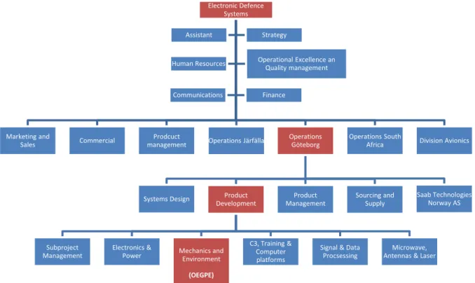
businesses, Aeronautics, Dynamics, Electronic Defence Systems, Security and Defence Solutions, Support and Services and Combitech, which is an independent subsidiary of SAAB. Below is an organisation chart of SAAB EDS (see figure 1.1), the red boxes notes the branch in the organisation tree that requested this thesis work. (saabgroup.com, 2013)
Figure 1.1 Organisation overview
Electronic Defence Systems
Marketing and
Sales Commercial
Prodcuct
management Operations Järfälla
Operations Göteborg
Systems Design Product Development
Subproject Management
Electronics &
Power Mechanics and Environment
(OEGPE)
C3, Training & Computer platforms
Signal & Data Procsessing
Microwave, Antennas & Laser Product Management Sourcing and Supply Saab Technologies Norway AS Operations South
Africa Division Avionics Assistant Strategy
Human Resources Operational Excellence an Quality management
Finance Communications
Chapter 1. Introduction
18 1.2 Project description
This is the translated project description (see appendix I) for the original project description
Simulation as a design aid
Increasingly more work connected to design, production and assembly is today being made with help from different types of 3D tools. With these tools designs can be analyzed in different ways and thereby ideas and thoughts can be tested before an actual physical model is produced.
The designers are currently using Pro/ENGINEER at SAAB EDS (OEGPE), although very little work is being done concerning simulations within the program. The aid trough simulation is in the form of material and structure calculations from OEGPEB, in different software than CREO 2.0, and production preparation in a 3D environment from OEGSPV.
A thesis work concerning mapping the possibilities for OEGPE to use simulation to a higher degree in the design work wishes to be performed.
The thesis work could consist of:
A study of literature concerning the work methods regarding simulations in the design and production phase.
A study of SAAB Aeronautics in Linköping and their work concerning simulations.
Mapping of the possibilities of working with assembly and maintenance simulation in CREO 2.0
Expected results:
A report highlighting the possibilities to use simulations in the everyday use of a designer within OEGPE
The thesis work is suitable for one or two people and you are studying a master or bachelor within mechanics or similar areas.
Chapter 1. Introduction
19
1.3 Purpose
The thesis work is concentrated on helping the designers find a way to work, this was to minimize errors in design that carries over from the design phase to the production phase and the finished product. This is to be accomplished by first finding the areas that need improving in the organization, and from that develop a method or a way for the designers to be able to verify their works maintainability and the process in which it is assembled. The initial plan was to do most of the work in the CAD software CREO Parametric 2.0 to develop a work process for the designers. A literature study on the subject of improving work with maintainability and the assembly process in a 3D environment was also planned. The method that was to be developed should improve SAAB EDS products maintainability and assembly process. At present SAAB builds mock-ups during the product development phase to find problem areas in their products, that is a time and resource consuming
practice and as such another interesting aspect is the possibility of making virtual mock-ups which would save time and money when compared to making physical mock-ups.
Therefore the purpose of this thesis work is to.
Develop methods for the designers to work by
Examine if the software CREO 2.0 could be used for that purpose
Propose improvements in the work that is already carried out
Examine the possibility of making virtual mock-ups
1.4 Problem formulation
This thesis is going to touch on the subject of using simulation as an aid in the design process. The thesis work was carried out during the period of May-August 2013 at SAAB Electronic Defence System in Gothenburg Sweden in the OEGPE department as noted in 1.1 background (see figure 1.1). At SAAB EDS radar installations for various governments and states are designed, built and maintained. The project SAAB wanted carried out was helping their design engineers verify their products maintainability and the ability to assemble them, before the products are taken into production. This was to be
accomplished by developing new methods of work for their designers to use in the 3D CAD environment CREO Parametric 2.0. SAAB EDS feel that there are opportunities for
improvement in the way they work and the methods they use. Therefore there are four main points SAAB want us to study.
SAAB wants a study regarding work with verifying assembly procedure and the maintainability in a 3-D environment to take place. To gather ideas and thoughts to develop a new method for their designers.
SAAB Aeronautics in Linkoping are further ahead in that field, therefore SAAB EDS requests a visit to SAAB Aeronautics to study the way they work, what methods they use, and how to best transfer their experiences back to SAAB EDS.
Chapter 1. Introduction
20
SAAB EDS also asks for a survey of how to best work in the software they are currently using, CREO Parametric 2.0, to be able to improve their assembly procedure and their products maintainability.
SAAB EDS expects a report that shows the opportunities and abilities of different methods and software that can be used to verify the maintainability and their assembly process. With a focus on methods for the software they are currently using (CREO Parametric 2.0) and how to best use it to its full potential.
SAAB EDS currently builds mock ups of their products during the product development phase. The mock ups are then reviewed by personnel from the different branches of the company, Product Development, Systems Design and Product Management (see figure 1.1). The purpose of the mock ups and their review is to try and find problem areas before the production start so as to avoid costly mistakes that has to be rectified during production. The process of making mock ups can be costly and also time consuming, as there may be a need to build several iterations of the mock up. It is however far better to build a mock up and discovering issues compared to discovering the when the have already been sent to production. The way SAAB works with mock ups is that they after each review build a new mock up to alter the problems found in the last review, this is done until a full review is passed. SAAB is interested to know if an alternate method that cuts down on the workload and the time it takes to build the mock up, which also could be easily applied at SAAB, could be found.
1.4.1 General
The overall problem that was discovered during the interviews at SAAB EDS in Gothenburg was that there was no clear guideline for the designers regarding how to incorporate maintainability and the assembly process in their design work. Guidelines are necessary to achieve maintainability and a good assembly process for the products being developed at SAAB EDS. The designers are at the moment left to solve the problems as best they can, which in itself is not a problem, as the designers are competent and educated in the software they are using. The problem occurs when work from different designers are put together in a bigger system, and there are as many solutions as there are designers. That leads to confusion. The designers may also lack a sufficient degree of overview on the complete system when designing their parts that make up the system, that lack of overview may make obvious mistakes such as mounting brackets and screws being covered “invisible” to the designer when looking at the parts or the assembly in CREO 2.0. When that happens maintainability goes down, as to be able to service the products the
maintenance staff may have to disassemble a large part of the product to be able to reach the part that has to be maintained. It might also result in a product that is not possible to assemble at all, which is something that has to be avoided.
1.4.2 Work method
As there is no set way so solve issues regarding maintainability and the assembly process a situation where the designers themselves, on their own initiative solve the issues in many different ways. Neither the designers nor the section managers felt that there was a clear guideline to follow. What they did agree on was that the
Chapter 1. Introduction
21
assembly process and their products maintainability needs to be a priority when designing new products and parts, in what way and how it has to be prioritized was however not as clear. As there is no clear description of how designers should view problems concerning maintainability and the assembly process it leads to problems for the designer, the assembly department and the maintenance department 1.4.3 Feedback
Another issue that was discovered was with the system currently used for feedback from the staff in the assembly hall back to the designers. The personnel in charge of assembling products report problems that have been found during assembly. The idea is that the designer should check that system regularly for updates and what problems have been found by assembly personnel so that problems get resolved in the next revision of the product. The search function of that system is very sensitive, so something as simple as a lower case letter instead of an upper case returns zero hits when in reality there may be many problems reported. Problems that the
designers may not even be aware it exists. This all leads to a system that is not used as effectively and maybe not even at all in some cases. As a result the assembly staff may become tired when reporting the same problem over and over again that they lose faith in the fact that the design department even tries to help them, while in fact the design department has failed to notice that there even was a problem to begin with.
1.5 Delimitations
The scope of this project is huge and therefore any deeper analysis will be left for more focused projects that may or may not take place in the future. We will focus on gathering information and ideas for further investigation by either SAAB or other students. As there is just not enough time to do everything we would like. We decided on gathering broad knowledge and present ideas for multiple sides of the problem instead of focusing on one particular thing.
One limitation that we faced was the fact that we didn’t have enough time to properly investigate all available software that could be used and therefore we focused on the software IPS, there may be better alternatives, but we have not spent much time trying to find them.
Another limiting factor was that during the last part of our project when we were trying to gather information on how the organisation was structured to handle questions from design engineers, most of the employees at SAAB EDS were on vacation. Any form of information gathering at that time was slow and hard to achieve, therefore we did not attain the
23
CHAPTER 2
Analysis
In this chapter important working methods for this thesis are presented and explained, the concepts that are explained are Model Based Definition or MBD, path planning, mock ups and interview techniques. They are explained in short to allow the reader to more easily understand the rest of the report. At the end of the chapter a documentation of the product development process at SAAB EDS is mapped out and presented to give knowledge of how products are developed and what the work in the thesis will affect.
2.1 Model Based Definition
The term MBD was first used in the aviation industry which pioneered the work method. MBD is a concept based on using a single 3D model containing all the information and data the product needs throughout the entire production process. In the beginning this was seen as virtual product development, the method has since grown and now spans the products entire lifespan from conceptual design to maintenance. All departments involved in the product are using the same 3D model and the information that it holds. This requires a system that can put the model in the centre and allow it to act as a hub with the model library in the centre, and all other functions spread around the outside(see figure 2.1). (Uimaniemi, Tomi. 2013)
Figure 2.1 From Design to Maintenance all the parties involved in the product use the same model and the information it contains.
It also requires that all the different parts in the development and all the way to maintenance use this concept, as the concept fails if not all parties involved in the product use the same work method. The MBD concept means that there is no more need for 2D drawings.
Chapter 2 Analysis 24 Deployment Initial Planning Planning Requirement s
Analysis & Design
Implementation
Testing
g
Requirements Evaluation
A product can be made completely in 3D and then gives the ability to simulate the assembly process step by step before actual manufacturing starts and the product is assembled. By doing this issues with the product can be detected and corrected without the expenses that would follow if the product would have gone straight to manufacturing without
verification through simulation. The connection with LEAN production is strong as MBD is developed to find problems early in the design process, this saves both time and money in the product development, in the products lifespan and maintenance. The information in the 3D model is used in every step of the process, and when data is altered the model is updated throughout the whole process which ensures that everyone is working with the latest updates. With verification in early stages you can reduce mistakes before the product enters manufacturing, you can also optimize and ensure maintainability and the assembly process before there is a finished product. (Uimaniemi, Tomi. 2013)
A desirable feature using MBD is the availability of early verification. Traditionally methods is based on 2D drawings which can sometimes be ambiguous and time consuming, especially when it comes to making changes in a part. A paper drawing also makes it more difficult to ensure the quality of the product, whilst using a 3-D model as base makes early verification possible when it comes to product and process solutions. Another positive aspect of MBD is that handling information digitally compared to using 2D drawings and the more traditional methods cuts down on the work of the administration. (Uimaniemi, Tomi. 2013)
MBD is a natural progression within the CAD methodology and was in the beginning used within product development in the virtual sense. The concept has changed over time and the MBD method is now intended to be used throughout the whole lifespan of a product, not just during the product development phase. A model based method of work is most efficient when used in all the different aspects of a products lifespan and affect each section, this makes it natural to use it throughout the whole process. (Uimaniemi, Tomi. 2013)
MBD has a clear connection to the method of Concurrent Engineering (See figure 2.2). A premise of working with MBD is being able to make changes in a model. That change is saved in a database which all sections use and work with. By doing this everyone is not only working with the latest updates but can also work simultaneously with the information
provided in the model. (Uimaniemi, Tomi. 2013)
Figure 2.2 Traditional “Waterfall” work flow compared to the method used in Concurrent Engineering. Requirement Design Implementation Verification Maintenance
VS.
Chapter 2 Analysis
25
The MBD method coincides with the working method of Concurrent Engineering which revolves around two concepts. The first is that during the early stages of the design phase every part of a products lifespan should be taken in consideration, from product
development, assembly, manufacturing to maintenance. The second concept is based on the idea that all work with a product shall be able to concur at the same time, i.e. concurrent. This makes the process time efficient since work can be performed simultaneously and sections that work in the later stages can voice their opinions much earlier. The ideas of Concurrent Engineering and MBD have common characteristics in the sense of working towards finding errors and correcting them in early stages. These two methods both require communication between the different sections, and if the communication fails, the methods become less efficient and can render the method obsolete. (Kusiak, Andrew. 1993)
2.2 Path planning
Path planning or motion planning has been studied extensively. It was first studied to find a solution to the “piano mover’s” problem, a primitive problem that faces the user with how to manoeuvre a rigid body, a piano, from one location to another while avoiding obstacles in the environment. The solution to this problem has helped evolve motion planning to address a huge variety of problems, ranging from animating digital characters to assembly sequencing and navigation of changing environments. Motion planning is based on
mathematics and in its simplest form it allows the user to take a three dimensional object and plan a path through an environment. The environment and its obstacles are considered known and stationary(See figure 2.3). (Choset et al. 2005)
Figure 2.3 Graphical illustrations of path planning and configurations
The key problem is moving the object through the environment without it ever coming into contact with the obstacles. To be able to do that one needs to know the location of every part of the object, this is the configuration of the object. The configuration space of the object is the space of all the configurations the object could take. Consider for example an
Obstacle Obstacle
Obstacle
Obstacle
Chapter 2 Analysis
26
object with a moveable arm. The configuration space of that object would be all the different ways the arm could be located. When trying to move the object through the environment one must be aware of the configuration, configuration space and the environment. The object being moved has 6 degrees of freedom, x, y, z (location) and pitch, yaw, roll (attitude). The problem is then to find a curve through the environment that connects the start point and the goal point and allows one of the configurations in the configuration space to move through it without making contact with the environment (See figure 2.4). (Choset et al. 2005)
Figure 2.4 graphical illustration of path planning and the proposed path for the L shape
2.3 Mock ups
Mock ups are early prototypes, often made from cheaper material and very often they are less intricate in their design than the finalized product. Mock ups are made to gather input from the end-user and other designers. When a mock up is made the user often “test” the product imagining it is a working product to find issues with its usability, and provide
feedback on how the product feels and handles. This feedback is valuable to the designers working on the product, as it is much cheaper to alter the products design before starting production. (Soegard, Mads. 2004)
Mock ups are good tools used for drawing out criticism from users and other designers as they are low cost. Therefore if a user or a designer spots an issue he is more likely to voice his opinion on a mock up rather than on an early version of a finished product, as it has taken more work to get the product to this early stage one is less likely to criticise it. (Soegard, Mads. 2004)
Chapter 2 Analysis
27
As mock ups are often made out of cheaper and more pliable material, for example cardboard or Styrofoam both the user and the designer can together change the design with the help of familiar tools. These tools can be anything from scissors to knives. Due to this collaboration mock ups can be seen as a discussion starter and facilitator. Not only the user and designer are involved, other designer may also be involved and as such may provide valuable feedback to the designer working on the product, and will also spread knowledge throughout the design team. (Soegard, Mads. 2004)
Mock ups enable early testing of the products usability, and as they are made of cheaper material they encourage experimentation with layout and functionality, and instead of focusing on the visual design of the product, the focus is put on the products content and usability. (Soegard, Mads. 2004)
2.3.1 Virtual mock ups
Virtual mock ups are another step forward over the normal mock ups. They are three dimensional projections, either on a computer screen or on a bigger screen using projectors. They are often viewed in full 3D to provide viewers with a better
understanding of the product. Designers value virtual mock ups since they allow the viewers, they may be end-users or people that are going to build the product, to more easily understand the assembly sequence of a product and therefore they can provide feedback. A virtual mock up may also help the onlookers to identify a
relationship between objects in the product. It creates a sense of scale for the viewer and as such creates a better understanding of how the product will work and behave when it is finished. (Filkins, Brian. 2012)
Making a virtual mock up and showing it to the end-user is a good way to verify the end-user gets the product that was ordered. If the end-user is not content with what is shown redesign may be necessary. Finding out that the end-user wants
something changed at an earlier stage in the product development phase saves on time, resources and money for both the developer and the buyer. (Filkins, Brian. 2012)
Making a virtual mock up is beneficial to the seller as it may be used for marketing purposes when showing potential customers their products capabilities and the benefits of using the product. (Filkins, Brian. 2012)
2.4 Interviews
At the start of the project it was essential to gather information about how SAAB EDS worked, what they wanted the project to bring and to identify improvement areas in their organisation. Therefore we decided interviews with personnel would be performed as it would be the best way of gathering the information we wanted. There were different kinds of interviews carried out with different people, some were semi-structured with a set agenda and a list of questions, and some were initially started as a semi-structured interview with the list and then deviated from there, and some were unstructured and conducted as a normal conversation. The e-mail interviews were carried out as structured interviews with a questionnaire the interviewee was to fill in and send back. The interviews are explained and presented below. They are presented as different types to bring clarity, they are however not mutually exclusive from each other and one should view them as stages on a graded scale rather than distinct types. (Gillham, 2005)
Chapter 2 Analysis
28 2.4.1 Structured interviews
Structured interviews are the primary tool in social survey research, were a group of people, for example teenagers or women 45+ are targeted. The questions should be closed, meaning that the questions should not be able to be interpreted in different ways for different people and the answers should be simple and short. The
questions are often regarding issues like TV viewing and the use of you mobile phone or similar topics. Structured interviews are often used when large amounts of interviews are going to be held, to minimize the workload for the interviewers. The structured interview is likened to a questionnaire with the difference that there is a person asking the questions rather than a piece of paper with the questions written on it. The result of the interview is limited by the fact that the questions are closed and it’s used more to build a quantitative picture rather than a qualitative one. (Gillham, 2005)
2.4.2 Semi structured interviews
Semi structured interviews is considered to be the most important interview type when conducting research interviews. The reason is that it is both flexible and the data acquired is of good quality. The drawbacks of this type is that it takes a lot of time to prepare the interview, analyse the interview and then compile it and present it in a way that the data is comprehensible. Semi structured means that the
questions asked are the same for all of the people involved. The questions are focused on a topic but are still open enough to allow the recipient to interpret the question and answer from his or her own experience. If the interviewer feels that the interviewee has not spontaneously answered the question completely,
supplementary questions, probes, are asked to try and get a better and more focused answer. Roughly the same amount of time is allowed for all the interviews. (Gillham, 2005)
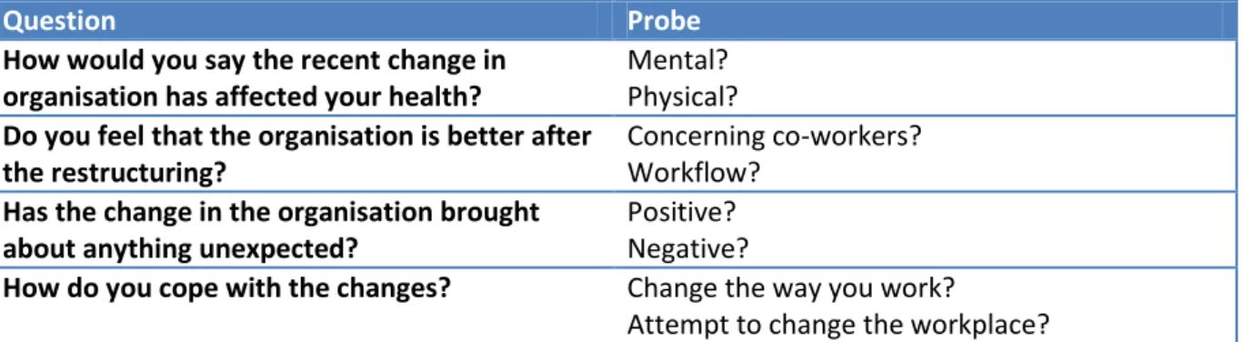
Probes are single words or short sentences used to get the interviewee to elaborate their answer when the interviewer thinks there is more to get out of the interviewee. A good probe can often get the interviewee to elaborate their answer and the result is qualitative answers that can more easily be used when analysing and comparing answers as the spread of the answers can be controlled with probes. Down below (see table 2.1) are a few examples of questions and probes related to those questions to try to give a better idea of what a probe is. They can be seen as a nudge in the right direction to get the interviewee to open up. (Gillham, 2005)
Question Probe
How would you say the recent change in organisation has affected your health?
Mental? Physical? Do you feel that the organisation is better after
the restructuring?
Concerning co-workers? Workflow?
Has the change in the organisation brought about anything unexpected?
Positive? Negative?
How do you cope with the changes? Change the way you work?
Attempt to change the workplace?
Chapter 2 Analysis
29
Collecting the data during the interview can be done in many different ways,
transcribing it while the interview is taking place is one method. Another is to record it and transcribe it later. Recording it is the preferable way as much information may be lost otherwise as the interviewer only will have time to write down keywords. Trying to transcribe during the interview means the interviewer first have to interpret the person being interviewed and note down key words, then interpret their own keywords when making a fuller transcription of the interview at a later date. A combination of the two can also be used, writing down keywords and then listening to the recording of the interview when making a transcription of the interview. (Gillham, 2005)
2.4.3 Unstructured interviews
The unstructured interview is used for gathering knowledge and information when the interviewer doesn’t know what information is there to be gained. The person being interviewed leads the way and tells the story, and the interviewer follows along and asks questions regarding the topics the interviewee talks about. Unstructured interviews are primarily used in three ways, as an initial technique to gather ideas for later more structured interviews, or where the person being interviewed may be inhibited by a more structured interview and lastly when you are more interested in a person and his or her experience and the questions will only reveal so much. Where letting the person talk freely without the constraints of set questions will yield the best result. (Gillham, 2005)
2.5
Product development process at SAAB EDS
(TRW) (DR) (TRW)(DR) (TRW) (DR)
(HWR)
Figure 2.5 Process overview for Mechanics and Cable D esign
Figure 2.5 shows the product development process at SAAB EDS, and the reviews it contains. There are three types of reviews, Technical Review, TRW, Design Review, DR and Hardware Review, HWR. Preceding the technical reviews and the design reviews a number of workshops are held to facilitate the development of the product.
The purpose of the review process is assuring quality in the design. By holding the reviews displayed in figure 2.5 a flawless, robust, and verified product can be manufactured and delivered. (Internal SAAB document. 2012)
Conceptual
Design
Physical
Design
Design
Test
Preliminary
Active
Released
Change
Management
Continuous workshops Continuous workshops SupplyChapter 2 Analysis
30 2.5.1 Technical reviews
Technical Reviews or TRW are normally held for units or parts of units, this usually means that many documents are reviewed at the same time. The focus of the TRW is on the factual content of the document, as well as technical solutions of the product. A new document must have undergone a TRW to be able to get assigned the status Released, although simple components at the lowest level such as internal components in electronic equipment may be released without a TRW or DR but would have had to go through a number of workshops. The observations and points requiring attention during the workshops must all be addressed and checked off during the TRW. SAAB has an e-mail template to facilitate the summoning of participants to ensure that all the departments concerned will be summoned and be able to participate in the development. The TRWs are conducted in the same way throughout all of the different stages of product development. (Internal SAAB document. 2012)
2.5.2 Design reviews
The DR is the conclusion of each phase within the MCD. It is a summarising design review of the product’s status. The associated documentation must be verified trough the DR so that it has been prepared and relevant status codes for the product can be set in IFS/PDM, Industrial and Financial Systems/Product Data
Management. During the DR it is intended to verify that associated documentation has been prepared and finalized. Observations from the TRW must all have been addressed and all documentation released before a DR is held. At each DR a review report is to be written. Design reviews differ from another depending on which phase the product is in. in the conceptual design phase the design review ensures that the concept meets the requirements in the design specification. In the physical design phase the design review ensures that the physical design meets the requirements set in the design specification. In the design test phase a function test is performed and if the product passes the review it is considered released. (Internal SAAB document. 2012)
2.5.3 Workshops
Workshops are meetings held during the conceptual design phase and the physical design phase, held so that those concerned can be involved in the development of the product and offer their opinions. They are meant to help the designers gather input and to help them find problems in the design before any of the reviews are held. Meetings will preferably be held on several occasions with a small number of participants. Participants may be other designers, production engineers, ILS and other members of the maintenance staff.
2.6 Gantt project time management
Gantt charts or Gant bar charts, as they are also known, were developed by Henry Gantt in the 1910s, it was based on work by a polish engineer Karol Adamiecki. Used by
manufacturing supervisors to see if the work was on time or not. On the X-axis time is registered, it could be days, weeks or months. On the Y-axis the tasks are listed in falling order. And across the chart from top to bottom a line noting the current time is displayed. This way it is easy to see whether the project is on, ahead of, or behind schedule (See
Chapter 2 Analysis
31 figure 2.6). (W. Durfee, T. Chase. 2003.)
Figure 2.6 Example Gantt chart showing the time axis, the falling tasks and the current time (wikipedia.org. 2013)
To create a Gantt chart one first needs to identify all the essential tasks for the project. For all task the earliest start date needs to be noted and an approximate duration. (W. Durfee, T. Chase. 2003.)
When all the tasks have been identified and the approximate time consumption has been noted, task relationship needs to be established. Some tasks need to be completed before others can be started, these are called sequential tasks. Other tasks can be performed at the same time as other tasks, these are called Parallel tasks. Tasks that are sequential need to have their relationship noted as it will help with scheduling the chart later. (W. Durfee, T. Chase. 2003.)
The third step in this process is to input all the data you have into either specialist software specifically made for Gantt charts or by hand on a piece of paper or other means to display your chart. (W. Durfee, T. Chase. 2003.)
Gantt charts evolve over time so new tasks may be found and they need to be input like the others with relationships noted and earliest start date and approximate time
consumption, during the project information on how far along the tasks are need to be updated into the chart on a regular basis. Depending on how long the project is data may need to be entered daily weekly or monthly. (W. Durfee, T. Chase. 2003.)
CHAPTER 3
Methods
In this chapter the methods used to gather and analyse information are presented. There are several different ways of conducting interviews as presented in chapter 2, this chapter
contains a presentation of what types were chosen and why. A description of Gantt project time management is also contained within this chapter.
3.1 Interviews
In the appendix there is a list of the interviews conducted during the project and the type of interview that was performed (see appendix II).
In our project we used structured interviews only in the form of e-mail interviews as we felt a more natural way of doing interviews would be best suited when talking to people face to face. The questions that were asked differed when interviewing the section managers and when interviewing engineers (as can be seen in appendix III and appendix IV). They also differed according to the interview type. The semi structured interviews often started out more structured and got more relaxed as it went on, in the end when we felt the main questions had been answered it took on a form more like a normal conversation to gather personal opinions and thoughts on the matter. The unstructured interviews were times were we went out and talked to the interviewee in the office environment about what experience they had of working with maintainability and the assembly process, and what they wanted us to explore regarding that subject. We also asked them if they had any experience in other software built for that purpose to see if we could gather material to compare our ideas against. During our visit to Linkoping we conducted one semi structured interview with the manager and the rest of the interviews were of an unstructured manner.
3.2 Gantt Chart
Our Gantt chart consists of 13 main tasks and 17 sub-tasks. The main tasks are: Project planning, interviews (Gothenburg), interview (Linkoping), Thesis day Linkoping, Start up and information gathering (checkpoint), tests in CREO, new work methods, interview with expert on collision control, tests in IPS, interviews with section managers, summary, report authoring and degree of project completion (See appendix V). The project planning spans 102 days of which 73 are workdays and yet a few more are taken up by holidays, on which SAAB EDSs offices are closed, all in all we had access to our workplace approximately 65 days. The time scheduled on the Gantt chart is not actual time it takes for us to complete each task but rather a time period which we planned to conduct our work within. For example conducting our interviews would not take 20 days, we however set aside 20 days for doing interviews, and during that time we planned, scheduled, conducted and
transcribed the interviews that were finished. The darker green rows contain information regarding our different subtasks and are a summary of the lighter green rows below it. We used a free Microsoft excel template from vertex42.com (Wittwer, Jon) to display our time management. The way a Gantt chart works was described in chapter 2 section 2.6 Gantt project time management. Our chart works in much the same way as described
Chapter 3. Methods
there. Tasks and Subtasks are listed on the y-axis, in chronological order with early tasks at the top and later task closer to the bottom. On the x-axis time in the form of days are
listed.There is a scroll list above the columns with days that enables you to scroll back and forth in the project, this is not necessary in our project as the whole project can be seen at the same time
At the top of the chart general information about the project can be found such as the name of the project, which the project leads are and todays date. Further down at the actual top of the chart columns are listed, they are: WBS (numbering of tasks), Tasks, Task lead (unused), Start date, End date, Duration (days), %complete, Working days, Days complete, Days remaining.
We began by planning out approximately how we thought the project would look. In the beginning the project planning was very different from how it is now, this was due to our original plan to create new working methods in CREO not being possible. Therefore restructuring of the project plan had to be made. The last change in the project plan was entered in the middle of June, apart from entering completion percentages which was continual work up until the last day of the project.
Once the chart had been set up, there was a daily work of opening the chart and entering what had been done, in the form of entering percentages in the corresponding column. By doing that and following the red line crossing the chart from top to bottom it was easy to see whether we were behind, ahead of or on schedule.
As can be seen in appendix V the project completion is listed as 98% this is due to the fact we were only able to finish 3/5 planned interviews with the section managers as they went home for vacation before we could schedule a meeting. This was left in the schedule as is but we consider the project finished.
35
CHAPTER 4
Results
In this chapter the information gathered from the different interviews is explained, the information is presented in a chronological way to try and get the reader follow along in the work that was performed. The chapter starts with interviews conducted in Gothenburg, continues with interviews in Linkoping, and ends with the finishing interviews back in
Gothenburg. No names of staff interviewed will be published as the employees of SAAB are company confidential. An introduction and education in IPS will also be presented.
4.1 Initial interviews Gothenburg
The interviews were held with personnel from the different sections and with people with varying job descriptions and titles, from designers, ILS (Integrated Logistics Support) personnel, production personnel to support and service staff. The first interviews were held with the section managers in the Mechanics and Environment work group. (See figure 4.1) The section managers that were interviewed were from, Subsystem design, Verification and Services, Mechanical Design, Laser & Antenna Design and Platform Design. Below is the organisation chart for the Mechanics & Environment department and sections belonging to it, the red boxes notes the OEGPEG section that had requested the thesis (See figure 4.1). (Saab organisation chart, 2013)
Figure 4.1 The Platform Design section along with the other sections in the Mechanics & Environment department
The reason for interviewing the section managers was to get an overall idea of the areas in which they saw room for improvement, for us to then build upon when interviewing the engineers that work at SAAB EDS. After all available section managers had been interviewed, the head of Verification & Services was not available at that time and was interviewed at a later date (see table 3.1). We continued with staff they thought would be relevant to the project. At every subsequent interview we asked for new recommendations of staff we could talk to
Mechanics & Environment
Chapter 4. Results
36
That would be of interest and could add something to the project. This continued until a comprehensive picture of the areas of improvements had been found and a sufficiently good overview had been built.
4.1.1 Interviews section managers Gothenburg
What was found during the interviews was that the Section managers felt that the software was not used to its full potential and that more could be done in the CAD environment. All of them also felt that there either didn’t exist any guidelines to follow or that the guidelines were not clear enough. One Section manager mentioned that he didn’t think the design specification A3 that are supplied when designing a new product even mentioned how to verify maintainability and the assembly process. Which he felt was a huge drawback that needed to be rectified if they were ever to improve the work they are doing. Another Section manager noted the difficulty in specifying exactly what needed to be taken into consideration when making the design specification A3, what are the criteria for maintainability and how can they specify that a part is possible to assemble in the design specification A3? What they felt was lacking was also that the 102-62 document which contain design demands on a subsystem level could not be broken down further, down to a level which could be used by the designer making his part in the CAD environment. One such criteria that he felt was lacking is the service time on a subsystem instead of the complete product, if the service times could be broken down that far it would be possible to easier set demands on the parts in the system. As it stands at the moment the demands are set by the designer while designing the part and these demands may or may not contradict the demands set in the 102-62. (Interviews conducted with Section managers in Gothenburg, May-June 2013)
All of the section managers agreed that the designer during the design phase had the definitive responsibility that their parts were designed in such a way that it was possible to easily disassemble and perform maintenance, and that they could easily be assembled during production. (Interviews conducted with Section managers in Gothenburg, May-June 2013)
4.1.2 Interviews design, systems and subsystem engineers Gothenburg The design engineers were interviewed following the interviews with the Section managers, they had varying amounts of experience on the job from a few months up to 10 years. Overall they all agreed that CREO works well for the purpose of
designing parts and assemblies, they however all wondered if it was used to its fullest extent, could there be extensions that would allow them to work more efficiently. And could they perhaps use CREO or any of its extensions to verify maintainability? (Interviews with design and subsystem engineers, May 2013) When it comes to verifying maintainability one engineer stated that the engineers do whatever they can to try to improve their products maintainability. The engineer didn’t feel it was a lack of motivation, nor the skill of the engineers, what the
engineer felt was the problem was the lack of a proper work method. The engineer stated that a large amount of responsibility is put on the engineer without any sort of clear support, the engineers don’t know where to turn with questions they have regarding their designs. They can however always look up where to turn but with a deadline hanging over their heads they don’t always have the time to navigate
Chapter 4. Results
37
through the organisation to find the help they need. This is an issue as they feel that many problems that may originate from this could have been avoided if they had a clearer idea of where to turn for input and support. (Interview with design engineer 4, 14 May 2013)
One engineer mentioned that he felt the reviews are good but the engineer thought that the personnel present at the reviews was not always from the right section in the company. The engineer also thinks that due to the staff at the review not being used to look at CAD models, they miss things they regard as obvious problems when they see a physical product as opposed to looking at the same problem on a computer screen. As such they don’t know what to look for and they pass the review without noting problems. When there later is a product, the same members of the staff that passed the review have come back and shown the designers problems, even though no change has been made in the CAD model. They now spot problems easier when there is a physical product. Getting feedback is very important to the designers(See Figure 4.2) (Interview with subsystems engineer 2, 30 May 2013)
Figure 4.2. The bother scale, tool for helping designers evaluate the feedback given from participants at a review. (20px.com. 2012)
Another engineer stated that there are checklists for product development, these checklists contain many different “boxes” that need to be checked, and there are “boxes” for maintainability and the assembly process. The checkboxes that currently exist only state that maintainability and the assembly process has to be taken into consideration. No more information of how and by what means it has to be taken into consideration exist. (Interview systems engineer, 14 May 2013)
Chapter 4. Results
38
All of the engineers had the same opinion on mock ups, they felt the practice of making physical mock ups was a good way to bring out problems that may not have been discovered by only working with the CAD models. When asked about the ability to make virtual mock ups the engineers agreed that it could be an excellent way to help them getting better at verifying maintainability and the assembly process. (Interviews with systems, design and subsystem engineers, May 2013) An education of how to and when to use mannequins was a topic many of the engineers brought up as they felt mannequins was another great way to illustrate how and where there might be problems especially with maintainability. The
engineers thought that placing a mannequin in the model gave them a better sense of scale and it allowed them to easier spot problem areas. They did however feel the mannequins were problematic to work with and they felt they needed some
education to utilize the mannequins to their fullest potential. (Interviews with systems, design and subsystem engineers, May 2013)
One engineer mentioned a system used to report problems found in production back to the design department, the engineer felt the system was not working the way it should. He explained that the vision for the system was that the production staff should enter problems found and how they solved the problem into a system that stores these solutions. The design department is then supposed to look over this system and use the solutions found in production when making the next design update. The problem with this system is that years may pass before the next design update takes place. And that in turn leads to the design department often missing the solutions stored in the system. When that happens and the staff in production find that a problem they reported years ago still exists in the product, they lose confidence in the design department. The engineer then stated he thought the production staff would like to give feedback directly to the designers rather than entering it into a system and then wait for improvement to happen. (Interview with design engineer 1, 13 May 2013)
Another area of improvement they asked for were a database of tools used by the assembly staff at SAAB EDS, these tools could be used in their work in the CAD environment to illustrate whether or not parts can be assembled. One example an engineer brought up was with one of their products. A weapon rack had been mounted in such a way that it was impossible to fit the tools needed to disassemble an electronics unit located nearby. Had the engineers designing this electronics unit and the engineer placing the weapon rack been able to use a tools database this problem could have been avoided according to the engineer. (Interview with design engineer 4, 14 May 2013)
Many of the engineers that were interviewed also stated they felt they didn’t know where to turn when they had questions regarding their design. They didn’t know which department and/or section that were responsible for the parts they were designing. For example one engineer stated that he could of course start asking his subproject manager or his section manager, but that there was not always time to “navigate” through the organisation that way. What they asked for was a short list that highlighted where to turn with what questions so they could make their work more efficient. Many of the engineers thought that not having to look for where to
Chapter 4. Results
39
turn would speed up the design process and would help the designers meet their deadlines. (Interviews with systems, design and subsystem engineers, May 2013)
4.2 SAAB Aeronautics
Interviews where held at Saab Aeronautics in Linköping to examine their way of work, and to look at the methods they use.They are using a working method that covers the
deficiencies that were found in SAAB EDS and the idea was to look at the organisation in Linkoping to see if and how their methods could be implemented in Gothenburg. They presented us with the concept MBD (Model Based Definition) and described how they worked with it, which departments did what, how the software they used worked and then moved on to showing a few examples in simulations and their applications. (Interview with method developers in Linköping, 22 May 2013)
4.2.1 Meeting with method developers
At first a meeting was held with two method developers at SAAB Aeronautics, they started by explaining the concept of their working method, Model Based Definition. They continued to talk about ways to implement the methods on a production process. The focus of the meeting was about the process of MBD usage in airframe design for Gripen E. The process started with the designers who worked with making a model in their software, CATIA, this model would be used throughout the whole process and all the information needed would be found here. (Interview with method developers in Linköping, 22 May 2013)
The process continues with what can be considered one of the most important parts, which is the verification of a product, to ensure that the product can be assembled properly without any complications and that the maintainability is held within standards. This is done through assembly simulations which are made in DELMIA. Production preparation groups at Saab Aeronautics are responsible for the order in which their products are assembled. The organisation also has staff that specialise in simulations regarding verification of maintainability and the assembly process. To help verify the work the designers are doing they can turn to those departments for help. By doing that they verify that the parts they have designed can be maintained and that their product can be assembled. The designers work mainly in CATIA which is the equivalent of EDSs CREO 2.0 where only simple visual verifications are made using estimations and they rarely come in contact with the simulation software. (Interview with method developers in Linköping, 22 May 2013)
After the assembly verification is complete the 3D design goes through to other sections, such as manufacturing, production and later on it is still used in
maintenance. In the production phase the 3D model is used in a way to help the process and the production staff to assemble it. Instructions have been made in a form that allows the personnel to see exactly how the product is intended to be assembled, similar to instructions that comes with different LEGO packs, the difference being that these instructions are simulated. (Interview with method developers in Linköping, 22 May 2013)
The method developers also explained the usage of mannequins in the CAD software. It was used to get perspective on the size of a product, which was a hard thing to comprehend in a 3D environment. They also used it to examine if you could
Chapter 4. Results
40
get between or reach specific parts of a product and also to see the line of sight of the mannequin. These were the simpler things that could be done with mannequins, but there was another aspect of the usage that was more complex, the ergonomic analysis of the mannequin. It was made to ensure that the production or
maintenance of a product would be possible for a person to perform without injuries. To do this you needed skill in both using the software and also expertise in
ergonomics. (Interview with method developers in Linköping, 22 May 2013) 4.2.2 Meeting with a simulation expert
After the meeting with the method developers, an introduction of the software
DELMIA was made, where a simulation expert demonstrated how work was typically performed. The example was a part of Gripen E and the simulation expert showed that the software could be used in two different ways concerning assembly
simulation. The first way was to do an automatic path planning, which was easier and took less time, but in some more difficult cases you had to use the second method which was to do the work manually due to the program not being able to automatically calculate a path. Doing the work manually meant that it would take time, days or even weeks compared to automatic path planning which took minutes. You would have to go through every frame of the simulation and adjust the part manually in every frame to get the part where it needed to be. The simulation expert stated that this wasn’t something the designers did and that you had to have
knowledge of the software to use it properly, although with the experience of the software it was a great way to ensure the assembly process and maintainability of a product. (Interview with simulation expert in Linköping, 22 May 2013)
4.2.3 Method developer introducing IPS
One of the method developers had previously worked at Volvo where they used different software for the purpose of simulating the assembly process. The software is from FCC, Fraunhofer Chalmers research Centre for industrial mathematics, and is called IPS, Industrial Path Solutions. The method developer talked favourably of the software and recommended us to take a closer look of the program to see if it was something that would be of interest of Saab EDS. Mainly because of the fact that it was software not bound to any of the big suppliers that often require one to get their entire suite of software to be able to use it. And as SAAB EDS was using CREO 2.0 which is not bound to any of the big suppliers such as Siemens or
Dassault, the expert proposed we got into contact with FCC. (Interview with method developers in Linköping, 22 May 2013)
4.2.4 Interview with system architect
One of the systems architect was involved with the introduction of MBD in SAAB Linkoping’s organisation in 1997. Getting his perspective and input was useful since he was facing the same questions SAAB EDS is facing now regarding implementing the MBD method of work. With the redesign of the Gripen weapon system, to
version C and D that started in 1997, the MBD method was implemented in Saab Aeronautics. They were faced with many questions concerning how to introduce the new method to their organisation. When would this happen? Who would be
responsible for what? Which department should do what? How are we going to do it? Which supplements are we going to use? One aspect of the method in particular was an instant time and resource saver, this was the possibility to design a whole
Chapter 4. Results
41
new product and the ability to verify the products assembly process which was all done virtually before a product had been manufactured. This is now being done preceding manufacturing for every new product. (Interview with a system architect in Linköping, 22 May 2013)
4.2.5 Interview with a design engineer
A design engineer offered knowledge of the working process and described the responsibilities as a designer. The engineer strengthened the previous statements that they mainly work in CATIA and can only do simple estimations to verify the assembly process. The engineer knew where help could be found when it was needed, which sections handled what, but in the end the engineer knew that he was responsible for the part under design. The engineer often turned to the product preparation group if there were any questions of a parts ability to be assembled. In the engineers experience it was an easy way to work and the engineer always got the help that was needed from the product preparation group. (Interview with a design engineer in Linköping, 22 May 2013)
4.3 E-mail Interview with expert on virtual mock-up
An e-mail interview with an expert on virtual mock-up was conducted to gather knowledge on how to best and most efficiently introduce the concept to SAAB EDS. The expert began the interview with stating the reasons for his company making virtual mock-ups, the
reasons that were mentioned were cost reduction as opposed to making a physical mock-up of their product and the flexibility it gives during product development. Cost goes down as one does not have to construct a physical mock up in a 1:1 scale, which is both time and resource consuming, the expert states that the first time cost of a mock up can be great and the fact you have to rebuild it when making changes adds to the material cost and the time spent. All in all the resources whether it is staff or material needed are reduced when working with virtual mock up versus physical mock up. The flexibility, according to the expert, comes from the ability to have multiple versions of the mock up available at the same time, being able to switch views whenever necessary also enhances the flexibility according to the expert. It is also stated in the interview that while a designer can get the virtual mock up on their own computer screen, the assemblies that are in question are so large that getting a good overview on normal computer screen would be impossible. Therefore the experts company decided to utilize a 3D-movie theatre, with a large screen (7.4m x 2m) when they displayed the mock up. The theatre being that large and in 3D makes it easier to spot conflicts and collisions in the design. (E-mail interview with expert on virtual mock up, May 2013)
The interview continued with the expert explaining how the company used mock ups and how a typical showing was prepared. First and foremost the expert states that it is
important to gather staff from all the different branches in the company that will be in one way or another involved in the products life span, there should be staff working with product development all the way to staff from the maintenance department and sales present when doing a showing. This is done to gather as many thoughts and different aspects that may be important for the product. (E-mail interview with expert on virtual mock up, May 2013)
4.3.1 Procedure, review of virtual mock up A normal review is prepared in the following way.