Modelling of FACTS Power System controller using IEC 61850
Johan Malmstr ¨om
johan.malmstrom@se.abb.com
DVA331 - Computer Science, Basic Level
Report
Advisor: Mats Bj ¨orkman
Examiner: Mikael Ekstr ¨om
Advisor at ABB FACTS: Carl Heyman
Abstract
The International Standard ”IEC 61850: Communication networks and systems for power utility automation”, describes different domains with-in power systems. The power system application Flexible Alternating Cur-rent Transmission System, FACTS, has not yet been described and can therefore not be modelled correct.
This report presents a suggestion on how to model FACTS Controllers in IEC 61850. Based on use cases for communication interfaces, defining operation modes and different control and protection functionality and analysing power system equipment used in FACTS Controllers the report extends existing logical nodes and introduces new logical nodes and common data classes. From a modelling perspective a use case for a Static VAR Compensator, SVC, have been used. The work includes a UML model of the suggested additions to the standard.
Contents
1 Thesis Description 1
1.1 Background . . . 1
1.2 Tasks . . . 2
1.3 Outline of this report . . . 2
2 Introduction to IEC 61850 3 2.1 History of communication in substations . . . 3
2.2 IEC 61850; the standard for Communication in power system substation . . . 3
2.3 Data modelling . . . 5
2.3.1 UML model . . . 6
2.4 Communication and data models in IEC 61850 . . . 6
2.4.1 Station Level . . . 7
2.4.2 Bay Level . . . 7
2.4.3 Process Level . . . 7
2.5 Brief introduction to System Configuration description Language, SCL . . . 8
2.5.1 Engineering process . . . 8
2.5.2 The SCL object model . . . 10
2.5.3 SCL Specification . . . 10
3 Introduction to FACTS controllers 12 3.1 History and introduction to controlling power transmission . . . 12
3.2 Shunt technologies of today . . . 12
3.2.1 Thyristor based FACTS Controller . . . 12
3.2.2 Converter based FACTS Controller . . . 13
3.3 Modern series technologies . . . 14
3.3.1 Fixed SC . . . 14
3.3.2 Thyristor Controlled Series Compensator . . . 14
3.4 Operating modes of a FACTS Controller . . . 14
4 Use case: SVC 15 4.1 Communication interfaces in a SVC . . . 15
4.2 Analysis of use case . . . 16
5 Operating and control modes of FACTS Controllers 18 5.1 Operating modes of FACTS Controllers . . . 18
5.1.1 Definition of a state machine for operating modes . . . 18
5.1.2 Control locations . . . 20
5.1.3 Degraded mode . . . 20
5.1.4 Relationship between different control modes and open loop control . . . 20
5.2 Voltage control . . . 20
5.3 Reactive Power Control . . . 22
5.3.1 Slow susceptance or VAr regulator . . . 22
5.3.2 External banks . . . 22
5.4 Power Oscillation Damping mode . . . 22
5.5 Parallel controllers . . . 24
5.6 Protective control modes . . . 24
5.6.1 Protection of FACTS controllers with power electronics . . . 24
6 Data modelling 28
6.1 Substation level of a FACTS controller . . . 28
6.2 Modelling logic and system state . . . 29
6.2.1 Controlling operation modes of FACTS device . . . 29
6.2.2 Voltage Control . . . 31
6.2.3 Reactive Power Control . . . 31
6.2.4 Modelling of POD Control . . . 31
6.2.5 Modelling of Parallel Controllers . . . 31
6.2.6 Reinsertion-logic . . . 34
6.3 Modelling of Protection control modes . . . 34
7 Analysing and modelling of Single Line Diagram objects 37 7.1 Mapping of traditional SCADA signal list items to IEC 61850, modeling Bottom-up . . . 37
7.2 Modelling primary equipment . . . 38
7.2.1 Indication and Control of Breakers and Switches . . . 38
7.2.2 Metering and Measured values . . . 38
7.2.3 Power Transformer . . . 38
7.3 Branches of shunt connected FACTS Controller . . . 38
7.3.1 Supervision of Power Electronics . . . 38
7.3.2 Reactive Branches . . . 39
7.3.3 Thyristor controlled Reactive Component branches: TCR, TSR and TSC . . . 41
7.3.4 Reactive component branch with a Voltage Source Converter: VSC . . . 41
7.3.5 Logical nodes for Reactive Components Branches . . . 41
7.4 Harmonic Filter . . . 43
7.5 Mechanically switched reactive components . . . 43
7.6 Fast protective device and by-pass gap . . . 43
7.6.1 Use case for Spark gap or Fast Closing Device . . . 43
8 Modelling of Distributed Energy Resources (DER), Wind and Hydro power plants 47 8.1 New domains with-in IEC 61850 . . . 47
8.1.1 DER . . . 47
8.1.2 Hydro power plants . . . 47
8.1.3 Wind power plants . . . 47
8.1.4 Other domains where modelling is needed . . . 47
8.2 Comparison and influences . . . 48
9 Conclusions 50 9.1 Future work . . . 50
A Svenska Kraftn¨ats Kraftsystemkarta 54 B Single Line Digram Series Capacitor, one segment 56 C Single Line Digram SVC 57 D Introduction to control system for FACTS controllers 59 D.1 Control system for communication, system interaction, protection and control of power electronics 59 E Published parts of IEC 61850 61 F Basic Types defined in IEC 61850-7-2 62 G Proposed instantiation 65 G.1 Nomenclature and structure set by the IEC 61850 . . . 65
G.2 Single Line Diagram items used in use case and example implementation . . . 66
G.3 Overview of IEDs, Logical Devices and Logical Nodes . . . 66
List of Figures
1.1 Single line diagram (SLD) of a SVC containing a thyristor controlled reactor, a thyristor switched
capacitor and a double tuned filter . . . 1
2.1 Data modelling in IEC 61850. Figure is part of IEC standard. . . 5
2.2 The UML model of the IEC 61850 domain, represents IEC 68150-7. Figure is part of UML-model of IEC 61850 standard [Kos14]. . . 6
2.3 Communication interfaces of IEC 61850. Figure is part of IEC standard. . . 7
2.4 The different SCL-files and their usage. . . 9
3.1 SLD for the Extremoz SVC deliverd by ABB to Mexico. . . 13
3.2 A simplified single line diagram of a STATCOM . . . 13
3.3 Single line diagram of a Series Capacitor, showing Disconnector on the line, and By-pass breaker in parallel with the capacitor. . . 14
3.4 Conceptual single line diagram of a Thyristor Controlled Series Compensator. . . 14
4.1 Single line diagram of use case SVC. . . 15
4.2 Communication interfaces for use case. . . 16
4.3 Use case for Operators interaction and relationship between the SVCs functions. . . 17
5.1 The state machine describe the operating modes of a FACTS Controllers. Steady states are marked with thicker frames and transient states with thiner frames. . . 18
5.2 State machine describing the relationship between control modes of a FACTS controller. . . 20
5.3 Typical block diagram of the Voltage Control for an SVC. Example from [MV02] . . . 21
5.4 A VI-diagram showing the operating characteristic of a shunt connected FACTS device with slow susceptance regulator. Figure is inspired by [MV02] . . . 22
5.5 Outline of SVC voltage control system with additional reference signal for POD . . . 24
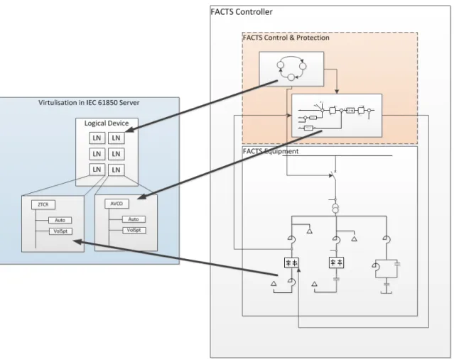
6.1 Mapping between real world FACTS and virtualization in IEC 61850. . . 29
6.2 UML representation of new Cxxx nodes. . . 30
6.3 UML representation of new CDC . . . 31
6.4 UML representation of new Axxx nodes. . . 33
6.5 UML representation of new RRIN node. . . 34
6.6 UML representation of new Pxxx nodes. . . 36
7.1 Example Holly STATCOM, Texas 80 Mvar inductive to 110 Mvar capacitive. . . 37
7.2 New LN Zxxx to represent SLD objects described in this report. . . 44
7.3 Use case for Spark gap or Fast Protective Device . . . 45
7.4 LN: XFPD to represent Fast Protective Device or Spark Gap . . . 46
8.1 Simplified network of a hydropower plant. Figure is part of IEC/TR 61850-7-510. . . 48
8.2 Conceptual organisation of DER logical devices and logical nodes. Figure is part of IEC 61850-7-510. . . 48
8.3 Model of FACTS Controller and virtualisation in IEC 61850 as described in this report. . . 49
A.1 The nordic transmission line grid system. The right to the picture belongs to SVK. . . 55
B.1 Single Line Diagram of a one segment Series Capacitor. . . 56
C.1 Single Line Diagram of a SVC with 2 TCR and 2 TSC branches. . . 57
C.2 Example Single Line Diagram of a Thyristor Switched Capacitor. . . 58
D.1 Communication structure of a shunt connected FACTS device. . . 60
F.1 Interface diagram of types defined in IEC 61850-7-2. Figure is part of IEC standard. . . 64
G.1 Overview of IEDs of the use case used in this report. . . 67
G.2 Overview of Logical Devices of one IED in the use case. . . 68
G.3 Overview Substation view of FACTS Controller. . . 69
H.1 Overview of additions to IEC 61850 presented in this report. . . 71
H.2 Overview of LN additions to IEC 61850 presented in this report. . . 71
List of Tables
2.1 Communications interfaces defined in IEC 61850 . . . 8
3.1 Thyristor controlled reactive components . . . 13
5.1 Operating mode and Operating location process data . . . 19
5.2 Voltage Control process data . . . 21
5.3 Reactive Power Control process data . . . 23
5.4 Process data for external banks . . . 23
5.5 Process data for Power Oscillation Damping. . . 24
5.6 Process data for Parallel controllers. . . 25
5.7 Protection related to voltage control. . . 25
5.8 Protection of thyristor controlled reactive components . . . 26
5.9 Overview of typical series capacitor bank protections. Based on IEC 60143-2. . . 27
6.1 Interpretation of logical node description tables . . . 28
6.2 LN: CPEM — Control of Power Electrical Machine . . . 29
6.3 LN: AVCO — Voltage Control . . . 32
6.4 LN: ARPC — Reactive Power Control . . . 33
6.5 LN: APOD — Power Oscillation Damping Control . . . 35
6.6 LN: CJCL — Control of parallel FACTS Controllers . . . 35
6.7 LN: PRCC — Current Protection of Thyristor Controlled Reactive Component . . . 35
6.8 LN: PTRV — Voltage protection of Thyristor controlled Reactive Component . . . 35
7.1 CDC: VST — Valve Status Common Data Class . . . 40
7.2 Process data for Reactive Component Branch . . . 40
7.3 Thyristor controlled Reactive Component process data . . . 41
7.4 Voltage Source Converter process data . . . 42
7.5 Abstract LN - ReactiveComponentBranchLN . . . 42
7.6 LN: ZTCR - Thyristor controlled reactive component . . . 42
7.7 LN: ZHAF — Harmonic Filter . . . 43
7.8 LN: XFPD — Fast Protective Device . . . 45
E.1 A list of published parts of the standard and the current edition w publication year . . . 61
F.1 The Basic Types as defined in IEC 61850 Part 7-2, Table 2[WG110a] . . . 63
Chapter 1
Thesis Description
The work presented in this report will be used by ABB in the work of defining the extension of the International Standard IEC 61850 with modelling of FACTS, HVDC and Power conversions1. Where needed, property of
ABB and IEC has been obscured or removed to protect from disclosure of intellectual property of these entities.
Figure 1.1: Single line diagram (SLD) of a SVC containing a thyristor controlled reactor, a thyristor switched capacitor and a double tuned filter
1.1
Background
The International Standard IEC 61850 is a standard for the design of electrical substation automation. Substa-tions are the building blocks of the electric grid and they connects the transmission and distribution networks. Substation automation is done with Intelligent Electronic Devices (IEDs), computer based systems used for control, protection, monitoring and operation of the substations. A Substation Automation System (SAS) is the combined system of IEDs. The SAS is also the interface for more advanced functions like power system management like energy management and planning. The abstract data models defined in IEC 61850 can be mapped to a number of protocols. Current mappings in the standard are to MMS (Manufacturing Message Specification), GOOSE, SMV (Sampled Measured Values), and soon to Web Services. These protocols can run over TCP/IP networks or substation LANs using high speed switched Ethernet to obtain the necessary response times below four milliseconds for protective relaying.
A flexible alternating current transmission system (FACTS) is a system composed of static equipment used for the AC transmission of electrical energy. It is meant to enhance controllability and increase power transfer
capability of the network. It is generally a power electronics-based system. FACTS is defined by the IEEE2as ”a
power electronic based system and other static equipment that provide control of one or more AC transmission system parameters to enhance controllability and increase power transfer capability”. Remote interaction with FACTS controllers have traditionally used SCADA-protocols or vendor specific solutions for communications. When the standard IEC 61850 for substation and inter-substation communication where introduced it lacked abstract data models for a lot of domains of substations like Wind and Hydro power plants. Among these domains a standard abstract data model describing FACTS controllers is missing.
1.2
Tasks
• Describe use cases for communication for the different part of a FACTS controller, and suggest solutions where IEC 61850 can be used. Example of affected parts of IEC 61850 is part 5, 8-1, 9-2 and 90-1.
This is described in Section 4.1 where the different communication interfaces of a FACTS Controller is showed and mapped on to the communication model of IEC 61850.
• Design and verify a data model. Propose Logical Nodes for describing the FACTS controller process. This might include extension of existing logical nodes, definition of new logical nodes, common data classes, etc. The additions shall be implemented in UML and conform to the standard. Example of affected parts of IEC 61850 is part 6, 7, 8 and 9.
The data modelling begins in Chapter 6.
• Comparison with other solution or data model within IEC 61850. Estimated time for this is 1 week. The comparison has resulted in influences on the modelling, but specific points are also discussed in Chapter 8.
• Presenting the result in a report and presentation. The paper should include introduction to Substation communication, IEC 61850 and FACTS Controllers as well as related work and future work.
1.3
Outline of this report
This report begins with a gentle introduction of the International Standard IEC 61850 and the power system application FACTS. Chapter 4 establish an example SVC which is used as basis through out the report for modelling of a specific case where the general case of FACTS would be to abstract.
The Chapters 5, 6 and 7 then contain the discussion and proposals on how to model a FACTS Power System Controller with IEC 61850. Additionally Chapter 8 compares with other domains of power system applications. Before the report ends with various appendices a glossary (on page 53) and the bibliography (on page 52) can be found. The appendices include more background information and further details, proposal of input to changes and additions to the IEC 61850-standard and a proposed structure of implementation.
Chapter 2
Introduction to IEC 61850
The international standard IEC 61850 is defined in a set of publications by IEC, International Electrotechnical Commission. The work with the standard started in 1995, and the first publications of the main parts of the standard were between 2002 to 2005. A list of current parts is supplied in Appendix E. The work with develop-ing IEC 61850 is done by Workdevelop-ing Group 10 (WG10) within Technical Committee 57 (TC57) of IEC1. The official
name of the standard was changed when Edition 2 started to be developed , to ”Communication networks and systems for power utility automation” from ”Communication networks and systems in substations” to reflect the extended scope of the standard.
This chapter gives a brief historical overview of substation communication and introduces the standard and its parts.
2.1
History of communication in substations
The electric utility power systems have used SCADA, Supervisory Control And Data Acquisition, communi-cations since the early electromechanical single-function protection and control relays where used[KWU+06,
Ger12]. The driving forces behind developing remote monitoring and remote control of key parameters where reliability(the customers of the power utilities demanded reliable electrical power) and that cost of labour at the manned substations where increasing. The early SCADA communication was very limited, generally monitoring of bus voltage and few aggregated alarms and control of circuit breakers. The communication was centralised and vendor specific[Nor08a, KWU+06].
The term IED, Intelligent Electronic Device, was introduced with microprocessor-based multifunction units. These IEDs could singly replace whole groups of the old electromechanical relays. The IEDs could perform all the functionality needed in a substation, e.g. protection, local and remote monitoring and control. With this development it arouse a need for efficient communication between IEDs. The first communications be-tween IEDs still used vendor specific and proprietary communications protocols. The result of this was very cumbersome and expensive protocol converters.
In North America the communication standard Utility Communication Architecture (UCA) [Nor08b] was used by power utilities. It defined protocols, data models and abstract service definitions2. European power
utilities used the IEC standard IEC 60870-53[TC590], which described a communication profile for sending
tele-control messages between two systems, based on a directly connected data line.
2.2
IEC 61850; the standard for Communication in power system
substa-tion
The objective with IEC 61850 was to develop one standard for substation communication, the drivers where to improve device data integration into the information and automation technology and reducing the costs for the whole life cycle of a substation. One can argue that the device cost for an IEC 61850 IED is higher but counting the cost for engineering, commissioning, operation, monitoring, diagnostics, asset management, and maintenance one can see that the total cost is lower[RM, Bla07] .
IEC 61850 started out to bring interoperability, i.e. communication exchange of information, between de-vices within a substation. By defining a standard communication interface the standard should make it
pos-1The scope of TC57 is Power systems management and associated information exchange.
2Based on physical, data link, and network standard and includes both TCP/IP and OSI communication architecture.
3IEC 60870 standards define systems used for tele-control, SCADA. IEC 60870-5 provides a communication profile for sending basic
sible for a substation to be engineered with devices from different vendors. IEC 61850 describes the use of a server-client interface, where the the servers (generally IEDs controlling equipment) provides information and receives commands to the clients (generally station computers or HMI). One difference between IEC 61850 and earlier SCADA protocols is that it has an object-oriented approach so that a device can describe its attributes when asked4.
Included in the standard is description of
Data modelling. The standard describes primary equipment (i.g. high voltage equipment like breakers and transducers) and the secondary equipment (protection and control IEDs) functionality associated with the primary equipment. The modelling is done using logical nodes (part 7-4[WG110c]) grouped together in logical devices. The logical nodes consists of data attributes with types defined in Common Data Classes (CDC) described in part 7-3[WG110b]. A logical device has as least one logical node (LLN0) and generally a logical node representing the physical device (LPHD). The logical nodes are associated in namespaces. The communication interface is described in part 7-2[WG110a] as Abstract Communi-cation Service Interface (ACSI). The communiCommuni-cation is mapped on MMS and Ethernet specified in part 8-1[WG111d] as Specified Communication Service mapping (SCSM). Data modelling is further discussed in Section 2.2 and is the main objective of this report.
Fast event handling. Generic Substation Events (GSE) is a peer-to-peer communication model described in IEC 61850 for fast event communication. GSE is subdivided in to Generic Object Oriented Substation Event (GOOSE) and Generic Substation State Events (GSSE). GOOSE data is directly embedded into Ethernet data packets. The data is grouped in to data set (status, value) and transmitted within a time period 4 ms on a Ethernet VLAN. The data packets are tagged using IEEE 802.Q priority tags. The combination of VLAN and priority tags gives the possibility of real-time data over a Ethernet network. GSSE is an extension of an older event communication standard5 and uses a status list (string of bits)
instead of data sets that GOOSE uses.
Reporting Schemes that describes how data is sent from server to client and conditions for sending the data. Part 7-2 defines report-control-block as an entity that
”shall control the procedures that are required for reporting values of data objects from one or more logical node to one client.”
Setting management. The standard defines how an instance of data object class can switch between sets of values. The model for this is called setting group control blocks (SGCB) and is defined in Part 7-2 [WG110c] of the standard.
Sampled value communication. The sampled value control blocks (SVCB) is also defined in part 7-2 of the standard. The sampled measured value communication is a method for transmitting measurements from transducers like CTs, VTs and digital I/O. Several transducers can be connected to a merging units that transmits the analog values using Multicast service (MSVC) over Ethernet or Unicast service (USCV) over serial links (point-to-point). The concept of merging units enables sharing of I/O signals with several IEDs. Sample value communication is described in [WG111c].
Commands. The standard defines two type of commands direct-control and select-before-operate. The latter can be seen as selecting action and then submitting (or cancelling), this type of control is common in control systems where actions needs confirmations.
System and project management. Part 4[WG111a] of the standard describes the engineering and processes of system and project management of a Utility Automation System. For instance Part 4 defines different classification, categorisation and types of parameters, engineering and system tools requirement and documentation requirements.
Configuration language for data definition and storage. Part 6 [WG109a] of the standard describes SCL, the Substation Configuration Language which purpose is to describe the exchange of data between a system configuration tool and IED configuration tool. The IED tool is usually vendor specific but the system configuration tool is generic. To provide this interoperability SCL is used to provide functional specifica-tion input to SAS engineering, describe IED capability descripspecifica-tion and the SA system descripspecifica-tion. SCL is further introduced in Section 2.5.
4Excluding UCA which also has an object-oriented architecture.
General requirements of equipment used for Utility Automation Systems are defined in Part 3 [WG113b] of the standard. Part 3 includes requirements for
”mainly regarding construction, design and environmental conditions for utility communi-cation and automation IEDs and systems in power plant and substation environments. These general requirements are in line with requirements for IEDs used in similar environments, for example measuring relays and protection equipment.”
Verification of conformance to the standard is described in Part 10 [WG112a] of the standard.
Figure 2.1: Data modelling in IEC 61850. Figure is part of IEC standard.
2.3
Data modelling
Modelling in IEC 61850 is introduced in Part 1 [WG113a] and further explained in Part 5[WG113c] and 7-1[WG111b] of the standard. Figure 2.1, published in Part 1, shows the different layers discussed when mod-elling. The breakdown starts from the physical device, often an IED, and breaking it down to Logical Devices. A logical device represents a group of logical nodes and defines the communication access points of an IED. The standard does not restrict the way on how to set up a logical device, but it can only be on one physical device. In Figure 2.1 the logical node LDx have instances of two logical nodes XCBR1(instance of logical node XCBR6)
and MMXU1(instance of logical node MMXU7). Logical devices enables modelling of multi-function IED’s.
A logical device is a rather simple construct with constrains that may complicate the modelling of complex hierarchies, the standard exemplifies with distance protection and this report will provide another example where the basic functionality is not sufficient. In the Edition 2 of Part 6 [WG109a] and Part 7 of the standard introduce the concept of an hierarchy of Logical Devices. This concept makes is possible to manage nested functions and sub-functions.
A Logical Node represent the lowest level of a virtualised function of physical equipment. The standard de-fine a logical node as[WG113c] ”object where standardised data for communication are grouped in according to their relationship to application functions” with the note ”The granularity of data or to how many logical nodes (LN) the data are distributed depends on the granularity of functions. The granularity stops at the small-est function parts which may be implemented as single- stand-alone functions acting also as atomic building blocks for complex functions. The logical nodes may be seen also as containers containing the data provided by a dedicated function for exchange (communication). The name of the logical node is than the label attached to this container telling to what function the data belong. Logical nodes related to primary equipment are not the primary equipment itself but a data image in the secondary system needed for performing the applications functions of the power utility automation system.”
A Logical Node is built up with properties called Data Objects. The type of a data object is a Common Data class. Common data classes are defined in Part 7-3[WG110b], and has been defined for:
1. Status Information 2. Measured information
3. Controllable status information
4. Controllable Analogue set point information
6XCBR is ”used for modelling switches with short circuit breaking capability”[WG110c].
5. Status settings 6. Analogue settings
The Data Attributes holds the actual data and are derived from the basic types, defined by the standard in Part 7-2. The basic types is quoted in Table F.1 and the relationship between the defined types in Part 7-2 is visualised in an UML interface diagram in figure F.1.
2.3.1
UML model
Figure 2.2: The UML model of the IEC 61850 domain, represents IEC 68150-7. Figure is part of UML-model of IEC 61850 standard [Kos14].
UML was chosen in 2010 to describe IEC 61850 content. The expected benefits of for the standard is to increase the consistency and facilitate the extension of application domains for IEC 61850. To initiate this work a specific task force within TC57 WG10 was formed. The work with the UML model is ongoing, and the model is used to describe the amendment to the standard referred to a as Edition 2.1 of Part 7.
The UML model chosen for this work was the latest available in December 2014[Kos14].
2.4
Communication and data models in IEC 61850
This section describes the different levels in an substation and the communication interfaces between them. In Section 6.1 the relation between the a substation and FACTS Controllers are discussed.
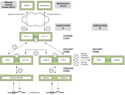
Figure 2.3: Communication interfaces of IEC 61850. Figure is part of IEC standard.
The Figure 2.3 is used in the standard to describe all the different communication interfaces to IEC 61850. The figure can be interpreted either logical or physical. The meaning of the interfaces enumerated in the figure are shown in Table 2.1. In the table one can also find where the communication is defined (if relevant). The following sections will introduce the different logical and physical properties of the layers and the modelling suggested by the standard.
2.4.1
Station Level
The physical interpretation of Station Level is the for example station Human machine interface (HMI) for the operator’s workplace and interfaces for remote communications.
The logical interpretation of station level functions are described in Part 5 of the standard as ”There are two classes of station level functions:
Process related station level functions are functions using the data of more than one bay or of the complete substation and acting on the primary equipment of more than one bay or of the complete substation. These functions communicate mainly via the logical interface 8.
Interface related station level functions are functions representing the interface of the SAS to the local station operator (Human machine interface (HMI)), to a remote control centre (Tele-control in-terface (TCI)) or to the remote engineering place for monitoring and maintenance (Tele-monitoring interface (TMI)). These functions communicate via the logical interfaces 1 and 6 with the bay and via the logical interfaces 7 and 10 to the outside world.”
2.4.2
Bay Level
At Bay Level the physical interpretation consists of devices for control, protection or monitoring units per bay. At bay level function can be local, where data is acquired by sensors, like current transformers (CT) and voltage transformers (VT), and actions are performed by actuators (switches) in the same bay. If functions uses sensors and actuators in more than one bay, they are referred to as distributed. The standard describes the logical interpretation in Part 5 as:
”Bay level functions (see bay definition above) are functions using mainly the data of one bay and acting mainly on the primary equipment of one bay. These functions communicate via the logical interface 3 within the bay level and via the logical interfaces 4 and 5 to the process level, i.e. with any kind of remote I/Os or intelligent sensors and actuators. Interfaces 4 and 5 may be hardwired also but hardwired interfaces are outside the scope of IEC 61850 series.”
2.4.3
Process Level
Process level physical devices are typically remote I/Os, intelligent sensors and actuators. The process level functions in a substation needs an interface for binary and analogue I/O, to process orders from the
function-Table 2.1: Communications interfaces defined in IEC 61850
Index Communication Defined in Part
1 protection-data exchange between bay and station level
2 protection-data exchange between bay level and remote
protection (e.g. line protection)
3 data exchange within bay level
4 analogue data exchange between process and bay level
(samples from current transformers and VT)
9-2
5 control data exchange between process and bay level
6 control data exchange between bay and station level
7 data exchange between substation (level) and a remote
engineer’s workplace
8 direct data exchange between the bays especially for fast
functions like interlocking
9 data exchange within station level
11 control-data exchange between the substation and remote
control centre(s)
90-2, Not published (Decem-ber 2014)
12 control-data exchange between substations. This interface
refers mainly to binary data e.g. for interlocking functions or other inter-substation automatics
90-1
ality, generally implemented in bay-level IEDs. The logical interpretation is described in the standard: ”Process level functions are all functions interfacing to the process. These functions communicate via the logical interfaces 4 and 5 to the bay level.”
2.5
Brief introduction to System Configuration description Language, SCL
The System Configuration Language (SCL) is defined in Part 6 of the Standard [WG109a]. SCL is the configu-ration description language used for describe a SAS and its IEDs. The language is based on XML. The purpose of SCL is described by the standard as
”It is used to describe IED configurations and communication systems according to IEC 61850-5 and IEC 61850-7-x. It allows the formal description of the relations between the utility automation system and the process (substation, switch yard). At the application level, the switch yard topology itself and the relation of the switch yard structure to the SAS functions (logical nodes) configured on the IEDs can be described.”
The languages is described both for a engineering process and for an configuration process.
2.5.1
Engineering process
The engineering process is defined in SCL in how to allow the exchange of information as configuration data between configuration tools. The exchange between the different tools is based on different file-type. The types of SCL-files and their role are listed below and also mapped in Figure 2.4.
1. IED Capability Description, ICD-file, is used for describe the capability (Logical Nodes) of an IED. 2. System Specification Description, SSD-file, describes the single line and functional requirements of
Log-ical Nodes.
3. System Configuration Description, SCD-file, is the definition of a specific SAS and includes communica-tion to the LN allocacommunica-tion (on IED-level)
4. Substation Configuration Description, CID-file, is a part of the SCD-file concerning a specific IED. It is used for IEC 61850-configuration of the IED.
5. Instantiated IED Description, IID-file, provides a subset of the specific IED configuration in relation to the configured data model
6. System Exchange Description, SED-file, to be used by the System Configuration Tool for configuration of communication between the systems.
2.5.2
The SCL object model
The SCL language can be used to describe the primary/power system structure, the communication system, application level communication, each IED, each instance of logical nodes and relationships between the log-ical nodes and IEDs on one side and the switch yard parts on the other side. Additionally SCL allows user specification/extensions of logical nodes by adding data objects.
To accomplish this an SCL-file has three main parts and a number of additional parts. The most common are:
Header -part serves to identify a SCL configuration file and its version.
Substation -part describes the switch yard equipment, including connection on single line diagram and the designation of equipment and functions
Product or IED-part includes all IEDs and logical node implementations.
Communication -part includes all communication objects as subnetworks and access points. It also includes the communication paths between IEDs to define client and servers.
DataTypeTemplates -part determines together with Part 7-3 and Part 7-4 of the standard the possible values for names of logical nodes prefixes, classes and instances.
The Substation- and IED-part may appear more than once.
2.5.3
SCL Specification
SCL is based on XML and to keep the syntax compact and extensible, SCL uses the type feature of XML. This enables the inheritance structure for elements. Almost all elements in SCL derives from tBaseElement base type. The t are part of the naming conventions used:
• schema type names start with the small letter t, as in tSubstation
• attribute group definitions starts with acronym ag, as in agAuthorization • attribute names start with a lower case letter, as in name
• element names start with a capital letter, as in Substation
The SCL file starts with the header or prolog part, then continues with the parts described above. The listing below is an simple example of an SCL-file (listed in Part 6[WG109a]:
<?xml version="1.0" encoding="UTF-8"?> <SCL xmlns="http://www.iec.ch/61850/2003/SCL" xmlns:xsi="http://www.w3.org/2001/XMLSchema-instance" xsi:schemaLocation="http://www.iec.ch/61850/2003/SCL SCL.xsd" version="2007" revision=?A?> <xs:element name="SCL"> <xs:complexType> <xs:complexContent> <xs:extension base="tBaseElement"> <xs:sequence>
<xs:element name="Header" type="tHeader"> <xs:unique name="uniqueHitem"> <xs:selector xpath="./scl:History/scl:Hitem"/> <xs:field xpath="@version"/> <xs:field xpath="@revision"/> </xs:unique> </xs:element>
<xs:element ref="Substation" minOccurs="0" maxOccurs="unbounded"/> <xs:element ref="Communication" minOccurs="0"/>
<xs:element ref="IED" minOccurs="0" maxOccurs="unbounded"/> <xs:element ref="DataTypeTemplates" minOccurs="0"/>
</xs:sequence>
<xs:attribute name="version" type="tSclVersion" use="required" fixed="2007"/> <xs:attribute name="revision" type="tSclRevision" use="required" fixed="A"/>
</xs:extension> </xs:complexContent> </xs:complexType> </SCL>
Chapter 3
Introduction to FACTS controllers
This report is in no way a complete introduction to power system controllers, but to understand the role of FACTS power controllers a basic introduction is given. The presented theories are not defined here but only given for background understanding. A source for a deeper introduction to FACTS Controllers is Thyristor-Based FACTS Controllers for Electrical Transmission Systems by Mathur and Varma [MV02].
3.1
History and introduction to controlling power transmission
Historically the Alternating Current (AC) power system consists of generators, transmission and distribution lines and loads. The generators, rotating synchronous machines, generate the power which is transmitted to the load which consume the power, both real and reactive. The load may be synchronous, non-synchronous and passive. The transmission line has an overall loop structure, where the distribution lines has a radial structure providing the power to a defined load. In an AC system the current and voltage alternates in a sinus wave, generally with a frequency of 50 or 60 Hz. As an example the nordic transmission grid system is illustrated in Figure A.1.
The current and voltage changes depend on the load on the power system. By reactive (VAR) compensation the described characteristics of the line can be changed depending on the load of the line. Traditionally shunt connected reactors can be used to minimise over-voltage under light load conditions and shunt connected capacitors can maintain voltage levels under heavy load conditions.
When transmission lines are long, series capacitive compensation can be used to shorten the ”electrical distance”. This is done by reducing the inductive line impedance.
In multi-line systems it happens that the transmission angle of a line changes to a value outside the design criteria for that line. To adjust the transmission angle of that line a phase angle regulator can be used. Phase angle regulators are not discussed further in this work.
The emphasis of this report is on shunt technologies.
3.2
Shunt technologies of today
The Static VAR compensator or SVC uses thyristor based valves to control the amount of impedance or ca-pacitance applied to the line. The SVC has no moving part as the synchronous compensators has, that’s why it’s called Static VAR compensator. The static synchronous compensator or STATCOM uses a voltage source converter to insert or reduce the reactive AC power of the power system. This gives a system with a much higher switching capability compared to a SVC as the thyristor is bound to ”zero-crossing” for switching while the voltage source converter can switch at any given moment.
SVCs and STATCOMs have different control modes as Voltage Control and Reactive Power Control. The different modes are introduced in Section 3.4 and further described and modelled in Chapter 5
3.2.1
Thyristor based FACTS Controller
The SVC history starts in the 1970s. ABB was one of the pioneers and have been a market leader since then. A SVC uses a combination of at least one thyristor valved controlled reactor or capacitor combined with harmonic filters and mechanically switched reactor or capacitor banks to regulate the voltage level of a power system. These elements of shunt connected units are usually called branches. The mechanically switched banks is used for to increase the total reactive power support outside the dynamic range. The dynamic range is specified by the size of the thyristor controlled reactors and capacitors. The rating of a SVC is given by the inductive and
Figure 3.1: SLD for the Extremoz SVC deliverd by ABB to Mexico.
Figure 3.2: A simplified single line diagram of a STATCOM
capacitive range in Mvar. For an example the rating of a SVC can be 75 Mvar inductive to 150 Mvar capacitive, continuously variable (-75/+150).
A shunt connected FACTS device can have one or more thyristor controlled reactive components, usually referred to as branches. There exist three types of Thyristor controlled reactive components listed in Table 3.1. The shunt connected FACTS device usually also have one or more harmonic filters and control shunt connected reactor or capacitors branches. Generally the passive, harmonic filters are used to improve voltage stability, filter harmonics and lowering resonance problems. A single line diagram of an ABB multi-branch SVC with harmonic filters is shown Figure 3.1.
Table 3.1: Thyristor controlled reactive components
Name Abbreviation Comment
Thyristor Controlled Reactor TCR Reactance connected in series with a bidirectional thyristor valve. The thyristor valve is phase-controlled. Equivalent reactance is varied continu-ously. The current through the reactor is controlled from full value to zero by adjusting the firing angle of the gate between 90 and 180.
Thyristor Switched Reactor TSR Same as TCR but thyristor is either in zero- or full-conduction. Equivalent reactance is varied in step-wise manner.
Thyristor Switched Capacitor TSC Capacitance connected in series with a bidirectional thyristor valve. The thyristor control is either in zero- or full-conduction. Equivalent reactance is varied in stepwise manner. Switching a capacitor leads to transient currents so to minimise this a ca-pacitor is always switched when the voltage across the switch is near zero. Therefor a thyristor switch is only used to turn on or off a capacitor.
3.2.2
Converter based FACTS Controller
A shunt connected FACTS device can have one or more Voltage-Source Converter (VSC) components or branches. A VSC can act as both as an inductive or capacitive component.Shunt connoted FACTS devices that uses VSC-technolgy are generally called a Static synchronous Compensator (STATCOM). A Single Line Diagram (SLD) example for a VSC can be seen in Figure 3.2.
Figure 3.3: Single line diagram of a Series Capaci-tor, showing Disconnector on the line, and By-pass
breaker in parallel with the capacitor. Figure 3.4: Conceptual single line diagram of aThyristor Controlled Series Compensator.
3.3
Modern series technologies
The figures 3.3 and 3.4 shows simplified single line diagrams of the two common series compensating tech-nologies, Fixed Series Capacitor (FSC) and Thyristor Controlled Series Compensation (TCSC). It exists a few other technologies but they are very rare and is not covered in detail in this report.
A detailed single line diagram of a Fixed Series Capacitor is shown in the Appedix B.1.
3.3.1
Fixed SC
The application FSC uses a fixed amount of capacitors to reduce the impedance while the TCSC uses capacitors together with a thyristor controlled reactor component so that the amount of impedance can be dynamically changed.
Fixed series compensators, pioneered by General Electric in the 1930:ies, are by far the most used series compensation, used on long power lines to reduce the electrical distance. The amount of capacitance can be varied by dividing the capacitors to segments of the same or different size of capacitance. The logic behind switching can be based on for instance the power flow of the line and the switching of this segments is done by by-pass breakers controlled by a controller. This is a rather slow control where changes can be measured in seconds. The switching is done by by-pass breakers, which by closing, by-passes the segments of the series compensator to decrease the capacitance and by opening, of the same by-pass breaker, includes the segment and by that increases the capacitance.
Capacitors are sensible to over current and over voltage so the capacitors are protected by an advanced scheme of protection. The protection schemes may include varistors that is dimensioned so that they conduct on a specific current level, triggered spark gaps that conduct on when the voltage between the gaps two conductors exceeds the gap’s breakdown voltage or triggered by the control, and a controlled by-pass breaker. The protection schemes are implemented in a control system where measuring points keeps track of currents, energy level in the varistor and frequencies of the system, etc.
3.3.2
Thyristor Controlled Series Compensator
With the TCSC it is possible to change the impedance of the line much faster as the thyristor based controlled component can switch in different impedance every cycle of the current.
The control modes of an TCSC are more advanced than for a FSC, an TCSC can be used not only for compensating of long transmission lines but also for power flow control and Sub-synchronous Resonance (SSR) mitigation.
3.4
Operating modes of a FACTS Controller
A FACTS controller can act in different control modes. The over all control is some way of control the voltage of the power grid, this can be done either using the voltage or the current as reference. As the resulting impact is on the grid voltage, both methods can be grouped in to ”voltage control”. More advanced features of a FACTS controller can be reactive power control and power oscillation damping. Voltage control and the more advanced features are described later in Chapter 5.
Chapter 4
Use case: SVC
For the use case I have chosen a SVC of generic size, with two thyristor controlled branches and two external reactive components. Figure 4.1 shows the SLD of the SVC and the item designations of relevant components. In this chapter I use SVC instead of FACTS Controller but from a modelling perspective it is equal, this use case is relevant for other types of FACTS Controllers too.
Equipment that needs to be modelled but is not present in the SLD is the control and protection system of the SVC. This chapter will go through communication and interaction interfaces and show needed modelling. The coming chapters will analyse the process items for this use case.
Figure 4.1: Single line diagram of use case SVC.
4.1
Communication interfaces in a SVC
In Section 2.4 the different communication interfaces of IEC 61850 was introduced. The Figures 4.2 and D.1 has been drawn to show the communication interfaces of the SVC use case. In Figure 4.2 I divided the interfaces into three different categories:
Vendor specific. I have identified three interfaces of the SVC device: Control Signals, Indication and Sen-sors. In this part the communication is either part of the intellectual property of the vendor or the time requirements are to high for IEC 61850 of today[WG113c].
One exception exist, the communication interface of sampled values and control data for substation relay protection. The communication in this layer is described in IEC 61850-9-2.
The counterpart of the FACTS device interfaces is the three logical subparts of the control system: Moni-toring, Control and Protection.
IEC 61850 Station Integration. The three logical subsystems of the control system has an interface towards the substation, external devices in the same or other substations and other FACTS controllers. The commu-nication methods introduced in IEC 61850-8-1 is used here, additionally the interface defined in IEC/TR 61850-90-1: Use of IEC 61850 for the communication between substations [WG110d] apply here.
Substation to Control Center. Includes the interfaces to and from the remote operators and EMS1of the
elec-trical network. When published, the interfaces defined in IEC/TR 61850-90-2: Using IEC 61850 for commu-nication between substation and control centres might be applied.
The FACTS device and the three logical subsystems described above forms the FACTS Controller and its control system.
The interface defined in the standard (Figure 2.3 and Table 2.1) is noted on the relations between the parts in the Figure 4.2. From this mapping the interfaces for 1 – protection-data exchange between bay and station level, 6 – control data exchange between bay and station level, 8 – direct data exchange between the bays especially for fast functions like interlocking, and 8 – control-data exchange between substations will be more explored in this report.
Figure 4.2: Communication interfaces for use case.
4.2
Analysis of use case
An operator, either from remote or local, interacts with the SVC by giving different commands and the operator also receives events and indications from the FACTS controller. In Figure 4.3 the different use cases is shown.
At interaction level the user controls what Operating Mode the SVC is currently in. The Operating modes are further described and defined in Section 5.1.1. Further the Operator configures the control mode of the SVC. The difference between operating modes and control modes are discussed in Chapter 5, and the different con-trol modes, Voltage Concon-trol, Reactive Power Concon-trol and POD Concon-trol is thoroughly described in Sections 5.2, 5.3 and 5.4. The same sections describes the different process data needed by the different control modes, and other process data related to equipment is described in Chapter 7. Together with the different control modes of the SVC, there are also Protection of the SVC. They are described and the process data for protections are listed in Section 5.6.
Chapter 5
Operating and control modes of FACTS
Controllers
This chapter describes the different states of a FACTS Controller, three common control modes on how the FACTS Controller interacts with the power grid and last interaction between parallel FACTS Controllers. While describing the different control modes, different important parameters are listed to be used later in modelling.
5.1
Operating modes of FACTS Controllers
The operating modes of a FACST Controller is described in this section by showing how the FACTS Controller operates and defining a state machine showing the different modes and the transitions between them.
5.1.1
Definition of a state machine for operating modes
Figure 5.1: The state machine describe the operating modes of a FACTS Controllers. Steady states are marked with thicker frames and transient states with thiner frames.
A FACTS Controller has different states or modes of operation. A general view of states can be seen in Figure 5.1. The figure does describe the state machine of a FACTS Controller, it does not describe the status of the IED or control system used for controlling the FACTS Controller, nor does it describe the control modes of the FACTS Controller.
Off | Trip The FACTS Controller is not active and in the current state, and conditions is preventing the device to be put in to service. The transition to the state ReadyToStart is triggered by conditions based on status for the equipment.
ReadyToStart The conditions needed to put the FACTS Controller in to operation are fulfilled. This conditions include that no alarm is active, all target and lock-out relays are reset, grounding switches at FACTS Controller bus are open, FACTS Controller disconnector switch is closed, grounding switches in each available branch are open, disconnector switches in each available branch are closed and valve cooling system is ready for start.
InOperation The FACTS Controller is started and running with given parameters for voltage control and connected to grid.
The state machine also includes transition states or sequences of actions. They can be described as follows: StartSequence By order from operator, the FACTS Controller is taking predefined actions to start the FACTS Controller and connect to the grid. If the sequence finishes successfully the FACTS Controller will be in state InOperation, on any failure a transition to the TripSequence state will occur. A predefined action in this transition state is that the operator can issue a Cancel command. If this is done a transition to the StopSequence-state will occur.
StopSequence By order from operator, the FACTS Controller is taking predefined actions to make a controlled stop of the FACTS Controller and disconnect from the grid. When the sequence is finished the FACTS Controller will be in state Off | Trip, and in under normal conditions a transition to the state ReadyToStart will begin.
TripSequence In case of a non-recoverable fault the FACTS Controller is taking predefined actions to make an immediate disconnection from the grid and a stop of the FACTS Controller. When the sequence is finished the FACTS Controller will be in state Off | Trip.
Table 5.1: Operating mode and Operating location process data Process
informa-tion
Type Unit Comment
Operation mode enumeration - The current operating state/mode.
0: OffTrip; 1: ReadyToStart; 2: StartSequence; 3: InOperation; 4: StopSequence; 5: TripSequence
Control Order enumeration - Command selected by operator.
0: Cancel; 1: ForcedStop; 2: Start; 3: Stop;
Sequence Status enumeration Sequence status :
0: NoSequenceRunnig; 1: SequenceRunning; 2: SequenceAborted;
Local control Binary indication Control Authority Local
Station control Controllable Binary indi-cation
Control Authority Station level Control locked to
local by key
Binary indication Control is switched to local, by
physi-cal key or logic switch Degraded
opera-tion
Binary indication The control is running with reduced
5.1.2
Control locations
The FACTS controller, as any substation equipment, can be operated from different control locations. The locations are usually identified as local, where the operation is done in front of the equipment, remotely from a substation control room and finally remotely from a control center. For safety reasons substation equipment can be locked, by key or logic, to only allow local operation. Indication of location is important process data for the operators regardless if they work local or remotely. The needed process data is given in Table 5.1
5.1.3
Degraded mode
Some FACTS controllers can be configured in such way that operation can be supported with reduced capacity. The reduction can be caused by faulty conditions, for instance that dynamic range of the controllable reactance is reduced due to thyristor failure. This can be marked using a substate called Degraded operation. The fault as such is registered by the faulty component and is tracked by the control algorithm as such. Table 5.1 includes the data needed for this.
5.1.4
Relationship between different control modes and open loop control
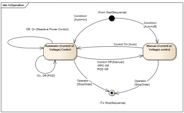
The control modes described above are all in closed loop control mode, where Voltage control is the main mode and Reactive Power control and POD is an additional controls. The control can also be set up in open loop, so that the control of the FACST device is set to a fixed output. This mode is referred to as manual mode.
In the operational state InOperation described in Section 5 an operator can change between different config-urations of control. In the Figure 5.2 the relationship between the control is drawn.
Figure 5.2: State machine describing the relationship between control modes of a FACTS controller.
5.2
Voltage control
The voltage control system is a closed loop system with control of the positive-sequence voltage or the mea-sured transmission system voltage (Vmeas) at the SVC/STATCOM bus. The voltage reference (VRef) is the
desired voltage level of the power system. The range of voltage reference is set by VRef M inand VRef M ax
re-spectively. The Slope or Droop, ideally the curve describing upper limit of the output of the SVC/STATCOM, shown as the dashed line in Figure 5.4. In practice the slope is set as percentage of deviation from the Vref.
The Gain setting corresponds to the short circuit power of the network in MVA, the unit is 1/s2. The voltage
∑ VRef Voltage Regulator VE Slope Susceptance Regulator VSR ∑ Thyristor Susceptance Control Measuring Circuit Measuring Circuit ISVC Mech. Equip. Control Logic BSET Transmission Voltage Imeas Vmeas + -+ +
-Figure 5.3: Typical block diagram of the Voltage Control for an SVC. Example from [MV02]
Table 5.2: Voltage Control process data Process
information
Type Unit Comment
Auto Control - Control for switching between
auto-matic or manual mode of the control VRef,
VRef M in,
VRef M ax
Control (analog value) Volt The desired voltage reference, with min an max-limits
Isec, IvscM in,
IvscM ax
Control (analog value) Ampere The current reference, with min and max-limits
QRef,
QRef M in,
QRef M ax
Control (analog value) VAr The desired reactive power reference, with min an max-limits
BRef,
BRef M in,
BRef M ax
Control (analog value) VAr The desired susceptance reference,
with min an max-limits. If min = max the output from the FACTS controller is fixed. This setting is used to set the control to a fixed output in manual mode.
Slope, SlopeM in,
SlopeM ax
Setting group (analog value)
Ratio The ratio of the voltage change over the SVC/STATCOM range and rated voltage
Gain, GainM in,
GainM ax
Setting group (integer value)
Ratio The regulator gain
5.3
Reactive Power Control
The reactive power control or regulator consists of two separate functions; slow reactive power or susceptance regulator and external bank controllers.
5.3.1
Slow susceptance or VAr regulator
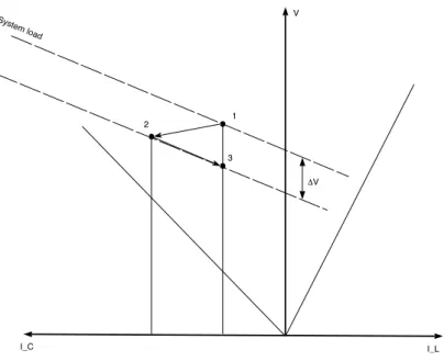
Syst em load 1 2 3 ΔV I_C I_L V
Figure 5.4: A VI-diagram showing the operating characteristic of a shunt connected FACTS device with slow susceptance regulator. Figure is inspired by [MV02]
When the automatic voltage regulator controls the FACTS Controller, a superimposed reactive power con-trol can also be activated. The FACTS Concon-trollers reactive power output returns slowly to a pre-set steady-state value, so that its var (usually in Mvar) capacity is held in reserve. The VI-diagram in Figure 5.4 shows in point 1 the output from the FACTS controller at a given system load. In point 2 the system load has decreased. The response output from the FACTS controller is now closer to the edge of its capitative capability. If the state is stable, the algorithm lowers the voltage reference, and by that increasing the response capability of the FACST controller. When stabilised, point 3 represent the new steady state.
The slow susceptance or reactive power regulator is slow, compared to the voltage control, and its output signal (∆VRP C) is added to the voltage reference signal in such a way that in steady state the SVC/STATCOM
will remain within a susceptance / reactive power window defined by two limits, one at the capacitive range and one at the inductive range. The needed process information is listed in Table 5.3, for an thyristor controlled device, one can use the susceptance,B as set point, for a voltage converter device one can use the reactive power,Q.
5.3.2
External banks
There might be other compensating components, such as reactor- or capacitor banks, in the same or nearby substations which is used to increase the reactive ability of the FACTS controller. The modelling example used in this report (see Figure 4.1) controls one Mechanically switched capacitor (MSC) and one Mechanically switched reactor (MSR), and in the real life example shown in Figure 7.1 the STATCOM1 controls three
ex-ternal capacitor banks. MSR- and MSC-banks are used together with the slow susceptance or reactive power regulator to achieve a situation where the steady-state reactive-power loading allows the SVC or STACOM to have effective response to disturbances. The needed process information is listed in Table 5.4
5.4
Power Oscillation Damping mode
The Power Oscillation Damping (POD) control is provided by modulation of the voltage reference in depen-dence of a measured quantity in the transmission system, P (t). The selected input signal is typically active
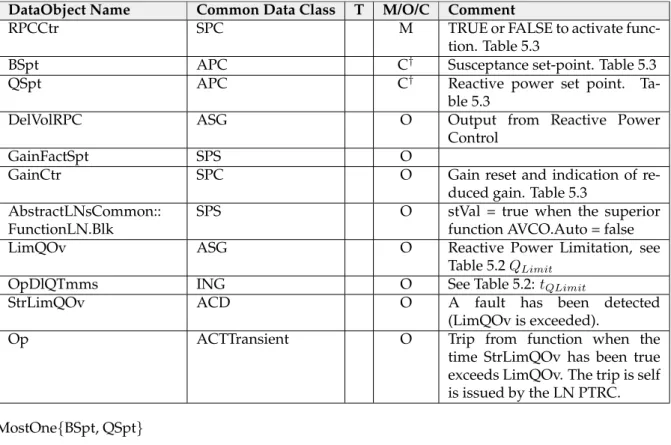
Table 5.3: Reactive Power Control process data Process
infor-mation
Type Unit Comment
Reactive Power Control
Control - Switch on or of the Reactive Power
Control, dependent on if the supe-rior voltage control function is in auto-matic, if not this functions is not avail-able and should be blocked.
RPC Blocked Control - Function is blocked by other function,
due to external requirements. Gain reset and
indication of gain reduced.
Control (Binary value) Ratio Indication that the gain is reduced by the predefined setting. The control, Re-set control, reRe-sets the gain to the prede-fined value.
Gain Setting Group (Float) 1/s2 The predefined reduction of gain
set-ting
Gain factor Float Percentage Percentage of full Gain
BSET Analogue Setting VAr Susceptance set-point for Reactive
Power Control function, can not be set if QSET is used.
QSET Analogue Setting VAr Reactive power set point for Reactive
Power Control function, can not be set if BSET is used.
∆VRP C Float Volt Output from Reactive Power Control
Table 5.4: Process data for external banks Process
information
Type Unit Comment
Unit start Control - Control of unit. Switch in or out
Unit active Binary value Boolean Shows if units are active.
Unit blocked Binary value Boolean Shows if unit is blocked due to
decharging. Increase/decrease
VAr
Control - Control amount of reactive power.
Reactive power
∑ Vref Voltage Regulator VE Slope Susceptance Regulator VSR ∑ Thyristor Susceptance Control Measuring Circuit Measuring Circuit ISVC Mech. Equip. Control Logic BSET Transmission Voltage Imeas Vmeas + -+ + -POD Control P(t) From Power System
V POD
Figure 5.5: Outline of SVC voltage control system with additional reference signal for POD
power flow or frequency deviation. The interface to the Voltage control is an additional Voltage reference, ∆VP OD. See Figure 5.5 for a schematic outline of the functionality. The needed process information is listed in
Table 5.5
Table 5.5: Process data for Power Oscillation Damping. Process
information
Type Unit Comment
POD-control Control Boolean On/Off of POD mode.
POD
func-tion Blocked
Control Boolean Function is blocked by other function,
due to external requirements.
∆VP OD Analogue Value Volt Additional Voltage reference from
POD-control P (t) active
power flow
Analogue Value P Input signal to POD control from
transmission system P (t)
fre-quency deviation
Analogue Value Hz Input signal to POD control from
transmission system
5.5
Parallel controllers
There might also be two or more co-located FACTS Controllers in the substation or nearby in the power grid. In such cases, some kind of overall joint control is required to prevent the devices to counteract each other. The needed process information is listed in Table 5.6
5.6
Protective control modes
Besides the described control modes described in this chapter, there is special protective control to protect the power system equipment and power electronics.
5.6.1
Protection of FACTS controllers with power electronics
The substation protection used together with shunt connected FACTS controllers are common substation (re-lay) protections. Relay protection has been the main focus for the development of IEC 61850, and is well
Table 5.6: Process data for Parallel controllers. Process
information
Type Unit Comment
Vref Analogue set point p.u. The voltage reference, normalised to
per unit
Gain Analogue set point - Current gain of the voltage control
Slope Analogue set point % Current Slope set point of the voltage
control Request to
optimise
Binary control - Normal operation or Request to start
optimisation Optimisation
prohibited
Binary control - OK or prohibit optimisation
described in many reports among other the Cigr´e2publication ”Applications of IEC 61850 Standards to
Pro-tection Schemes”[CIG13] so this report will not discuss relay proPro-tection of FACTS Shunt devices. The standard defines the LN PTHF for thyristor protection but it is a logical node related to protection of generators. In Table 5.7 and Table 5.8 the different protections are needed.
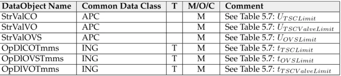
In the report I only cover the protection of thyristor based applications. The protection of converter based FACTS applications is similar, and is more or less repetition of the thyristor protections, I have decided to leave them for future work as they too is not covered by the standard in all details.
Table 5.7: Protection related to voltage control. Protection Name Service or information provided
Primary Current Limitation Part of voltage control. The primary current from the SVC is lim-ited by the SVC control system. Limiter in voltage control. Value, and above value trigger an event. Process data:
IP rimLimit Limit value
tP rimLimit Time before event trigger
Reactive Power Limitation Part of reactive power control. The capacitive/reactive power from the SVC is limited by the SVC control system. The setting level is determined by guaranteed capacitive/reactive power output. Limiter in reactive power control. Value, and above value trigger an event. Process data:
QLimit Limit value
tQLimit Time before event trigger
Secondary Voltage Limitation Part of voltage control. In order to prevent the TSC valve and ca-pacitors from overload at over-voltage conditions, the SVC con-trol will limit the SVC bus phase-to-phase voltage. Value, and above value trigger an event. Process data:
U2ndLimit Limit value
tU 2ndLimit Time before event trigger
5.6.2
Protection of Series compensation
The protection of Series Capacitors (SC) is well-defined in the International Standard IEC 60143-2 [TC312]. Table 5.9 lists the protection and actions related to each protection. By the same reason why the protection control functions of VSC is left for future work, the modelling of SC-protections is also left for future work.
2Cigr´e, the Council on Large Electric Systems, is an international non-profit Association for promoting collaboration with experts from
Table 5.8: Protection of thyristor controlled reactive components Protection Name Service or information provided
TCR current limitation In order to protect the reactors and the thyristor valves from over-current, the TCR is equipped with a current limiting control loop. Value, and above value trigger an event. Process data:
IT CRLimit Limit value
tT CRLimit Time delay before operate
TSC Valve over-current protec-tion
The over-current protection will prevent the thyristors from blocking after a very high surge current, e.g., due to misfiring of the thyristors. Process data:
IT SCLimit Limit value
tT SCLimit Time delay before operate
TSC Capacitor Over-voltage Protection
Usually called COVP, the protection will prevent the TSC from switching out, reducing thus voltage stresses on the capacitor bank and valve. Process data:
UT SCLimit Limit value
tT SCLimit Time delay before operate
TSC Valve Over-voltage Protec-tion
Usually called VOVP, prevents the valve from firing at high over-voltages leading to valve over-current. Process data:
UT SCV alveLimit Limit value
tT SCV alveLimit Time delay before operate
Over-voltage Strategy To protect valve and other components. Process data: UOV SLimit Over voltage limit
tOV SLimit Time delay before operate
Synchronising Voltage Supervi-sion
The synchronising unit is basically a Phase-Locked-Loop (PLL) that is used for synchronising the firing pulse generators of the thyristor valves with the SVC busbar voltage.
Usync Over voltage limit
tU sync Time delay before operate
Under-voltage strategy on the auxiliary power
Monitors the auxiliary power supply for the cooling system. If the voltage drops the valves can get overheated. The valve or converter can run for a limited time, but if the condition contin-ues the protection trips the FACTS controller.
U2:ndLimit Under voltage limit
Table 5.9: Overview of typical series capacitor bank protections. Based on IEC 60143-2.
Function Alarm
level
Bypass Lockout Temporary block insertion Reinsertion
Capacitor overload X X X X
Varistor overload X X X
Sub-harmonic protection X X X X
SSR protection X X
Line current supervision X
Capacitor unbalance X X X
Flashover to platform protection X X
Varistor failure X X
Bypass gap failure X X
Bypass switch failure protection: close failure X X Bypass switch failure protection: open failure X X
Bypass switch pole disagreement protection X X
Disconnector pole disagreement protection X X
Protection and control system failure X X
![Figure 2.2: The UML model of the IEC 61850 domain, represents IEC 68150-7. Figure is part of UML-model of IEC 61850 standard [Kos14].](https://thumb-eu.123doks.com/thumbv2/5dokorg/4820945.129851/13.892.192.704.246.892/figure-uml-model-domain-represents-figure-model-standard.webp)

![Figure 5.3: Typical block diagram of the Voltage Control for an SVC. Example from [MV02]](https://thumb-eu.123doks.com/thumbv2/5dokorg/4820945.129851/28.892.201.689.174.396/figure-typical-block-diagram-voltage-control-svc-example.webp)