SKI Report 2005:19
Research
DECOVALEX III PROJECT
Mathematical Models of Coupled
Thermal-Hydro-Mechanical Processes for
Nuclear Waste Repositories
Executive Summary
Edited by:
L. Jing
C-F. Tsang
J-C. Mayor
O. Stephansson
F. Kautzky
February 2005
ISSN 1104–1374 ISRN SKI-R-05/19-SESKI Report 2005:19
Research
DECOVALEX III PROJECT
Mathematical Models of Coupled
Thermal-Hydro-Mechanical Processes for
Nuclear Waste Repositories
Executive Summary
Edited by:
L. Jing¹
C-F. Tsang²
J-C. Mayor³
O. Stephansson¹
F. Kautzky
4¹ Royal Institute of Technology, Engineering Geology, Stockholm, Sweden ² Lawrence Berkely National Laboratory, Earth Science Div., Berkeley, USA ³ ENRESA, Madrid, Spain
4 Swedish Nuclear Inspectorate, Stockholm, Sweden
This report concerns a study which has been conducted for the DECOVALEX III Project. The conclusions and viewpoints presented in the report are those of the author/authors and do not necessarily coincide with those of the SKI.
Foreword
DECOVALEX is an international consortium of governmental agencies associated with the disposal of high-level nuclear waste in a number of countries. The
consortium’s mission is the DEvelopment of COupled models and their VALidation against EXperiments. Hence theacronym/name DECOVALEX. Currently, agencies from Canada, Finland, France, Germany, Japan, Spain, Switzerland, Sweden, United Kingdom, and the United States are in DECOVALEX. Emplacement of nuclear waste in a repository in geologic media causes a number of physical processes to be
intensified in the surrounding rock mass due to the decay heat from the waste. The four main processes of concern are thermal, hydrological, mechanical and chemical.
Interactions or coupling between these heat-driven processes must be taken into account in modeling the performance of the repository for such modeling to be meaningful and reliable.
The first DECOVALEX project, begun in 1992 and completed in 1996 was aimed at modeling benchmark problems and validation by laboratory experiments.
DECOVALEX II, started in 1996, built on the experience gained in DECOVALEX I by modeling larger tests conducted in the field. DECOVALEX III, started in 1999
following the completion of DECOVALEX II, is organized around four tasks. The FEBEX (Full-scale Engineered Barriers EXperiment) in situ experiment being
conducted at the Grimsel site in Switzerland is to be simulated and analyzed in Task 1. Task 2, centered around the Drift Scale Test (DST) at Yucca Mountain in Nevada, USA, has several sub-tasks (Task 2A, Task 2B, Task 2C and Task 2D) to investigate a number of the coupled processes in the DST. Task 3 studies three benchmark problems: a) the effects of thermal-hydrologic-mechanical (THM) coupling on the performance of the near-field of a nuclear waste repository (BMT1); b) the effect of upscaling THM processes on the results of performance assessment (BMT2); and c) the effect of glaciation on rock mass behavior (BMT3). Task 4 is on the direct application of THM coupled process modeling in the performance assessment of nuclear waste repositories in geologic media.
This executive summary presents the motivation, structure, objectives, approaches, and the highlights of the main achievements and outstanding issues of the tasks studied in the DECOVALEX III project. The main sources of the materials came from
summaries of the individual tasks prepared by the respective task force group leaders. They are:
Task 1 (Chapter 2): E. Alonso and J. Alcoverro Task 2 (Chapter 3): R. Data and D. Barr
Task 3-BMT1 (Chapter 4): T. S. Nguyen and L. Jing Task 3-BMT2 (Chapter 5): J. Andersson and J. L. Knight Task 3-BMT3 (Chapter 6): T. Chan and R. Christiansson Task 4 (Chapter 7): J. Andersson
The editors of this summary, together with the Steering Committee of the
DECOVALEX III project, feel very encouraged by the progresses which have been made during the project time and very positive about the usefulness of the achievements reached by the project to the larger international community of scientific research and management of radioactive wastes in different countries. A new phase of the
DECOVALEX project, DECOVALEX-THMC, is under preparation and we sincerely hope that the continued efforts will advance the science and improve the numerical tools
so that the disposal of radioactive waste could be managed on a more reliable scientific basis.
L. Jing, F. Kautsky, J.-C. Mayor, O. Stephansson and C.-F. Tsang Stockholm
Summary
This report is an executive summary of the works performed for the international co-operative research project DECOVALEX III (1999-2002). The report is divided into seven chapters. Chapter 1 provides a brief introduction to the project’s goals,
organizations, task definitions, implementation steps, overall achievements and lessons learned. The rest of the chapters are devoted to executive summaries of individual tasks covering mainly the case definitions, objectives, participating organizations and
research teams, the tools and approaches applied, main achievements and the lessons learned with outstanding issues for future studies.
Content
Page
1 Introduction 1
2 Executive summary-Task 1 5
2.1. Case definition and objectives 5
2.2. Participating organizations and research teams 8
2.3. Summary of results 8
2.4. Summary of scientific achievements of the task 11
2.5. Lessons learned and outstanding issues 12
3 Executive summary-Task 2 14
3.1. Introduction 14
3.2. Problem definition and work organization 15
3.3. Modelling approaches 15
3.4. Scientific achievements 16
3.5. Lessons learned and outstanding issues 17
4 Executive summary-BMT1, Task3 18
4.1. General definition of the problem 18
4.2. Implementation steps 18
4.3. Work organization and the physical processes concerned 20
4.4. Summary on scientific achievements 21
4.5. Lessons learned and outstanding issues 23
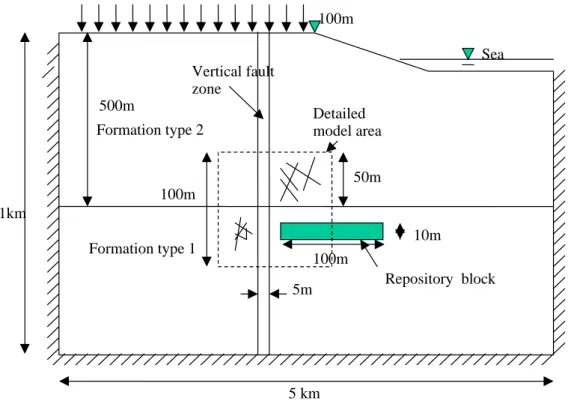
5 Executive summary-BMT2, Task 3 26
5.1. Background and objectives 26
5.2. Task organization 26
5.3. Problem definition 27
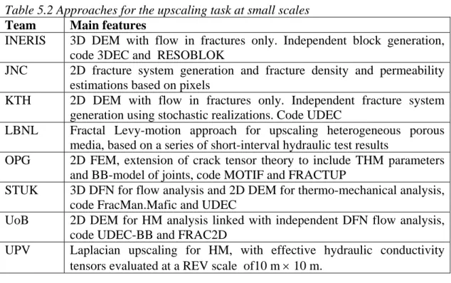
5.4. Modelling approaches 28
5.5. Scientific achievements 29
5.6. Lessons learned and outstanding issues 32
6 Executive summary – BMT3, Task 3 35
6.1. Background and objectives 35
6.2. Work organization 35
6.3. Problem definition 36
6.4 Modelling approaches 38
6.5 Summary of results 39
6.6 Scientific achievements 41
6.7 Lessons learned and outstanding issues 42
7 Executive summary – Task 4 44
7.1 Background 44
7.2 Objectives and scope 44
7.3 Works performed 44
7.4 Major findings through the questionnaire-answer forum 44
7.5 Presentation cases at the Task 4 themes of the 46
DECOVALEX III workshops 7.6 Issues discussed at DECOVALEX III workshops 46
7.7 Findings and implication of the different DECOVALEX III tasks 46
7.8 Lessons learned and outstanding issues 52
7.9 Conclusions 55
1. Introduction
The DECOVALEX III project is the third stage of an ongoing international co-operative project to support the development of mathematical models of coupled Thermal (T), Hydrological (H) and Mechanical (M) processes in fractured geological media for potential nuclear fuel waste repositories. During the first stage (May 1992 to March 1995), called DECOVALEX I, the main objective was to develop computer codes for coupled T-H-M processes and their verification against small-scale laboratory or field experiments. In the second stage, called DECOVALEX II, the main objective was to further develop and verify the computer codes developed in DECOVALEX I against two large-scale field tests with multiple prediction-calibration cycles, the pump test at the Sellafiled, UK, with a hypothetical shaft excavation and the in-situ THM experiment at the Kamaishi Mine, Japan. The DECOVALEX III project is the third phase of the DECOVALEX project series and was run through the period of 1999-2003. The DECOVALEX III project is initiated with two main objectives. The first is the further verification of computer codes by simulating two additional large scale in-situ experiments: the FEBEX T-H-M experiment performed in Grimsel, Switzerland, designated as Task 1, and the drift scale heater test at Yucca Mountain, Nevada, USA, designated as Task 2. The second objective is to determine the relevance of THM processes on the safety of a repository.
To achieve the second objective of DECOVALEX III project, three benchmark tests (BMT) are proposed to examine the relevance of THM processes to performance and safety assessments: 1) BMT1: the impact of THM processes in the near-field of a hypothetical repository in fractured hard rocks; 2) BMT2: homogenisation and upscaling of hydro-mechanical properties of fractured rocks and their impact on far-field performance and safety assessments; and 3) BMT3: Impact of glaciation process on far-field performance and safety assessments. These three BMTs are designated as Task 3.
An additional Task 4 was also organized to present the states of the current understandings on the impacts and treatments of the THM issues on PA and SA of nuclear waste repositories, from the views of the Funding organizations of the project, through compilation of answers to a questionnaire prepared for this purpose.
On September 25, 2000 the European Commission (EC) signed a contract of FIKW-CT2000-00066 "BENCHPAR" project with a group of European members of the DECOVALEX III project. The BENCHPAR project stands for ´Benchmark Tests and Guidance on Coupled Processes for Performance Assessment of Nuclear Waste Repositories´ and is aimed at improving the understanding to the impact of the thermo-hydro-mechanical (THM) coupled processes on the radioactive waste repository performance and safety assessment. The project has eight principal contractors, all members of the DECOVALEX III project, and four assistant contractors from
universities and research organisations.The project is designed to advance the state-of-the-art via five Work Packages (WP). In WP 1 is establishing a technical auditing methodology for overseeing the modeling work. WP´s 2-4 are identical with the three bench mark tests (BMT1 - BMT3) in DECOVALEX III project. A guidance document outlining how to include the THM processes in performance assessment (PA) studies will be developed in WP 5 which explains the issues and the technical methodology, presents the three demonstration PA modeling studies, and provides guidance for inclusion of the THM components in PA modeling.
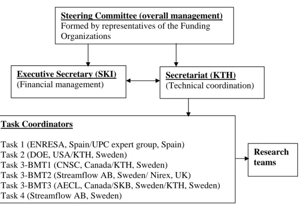
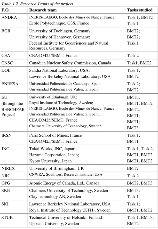
Tables 1.1 and1.2 list the Funding Organizations and their research teams of the Project. Figure 1.1 shows the organization of the project.
Figure 1.1: Organization of the DECOVALEX III Project. See Tables 1.1 and 1.2 for the acronyms of the organizations.
Table 1.1. Funding organizations of the project
Funding Organizations (Acronyms) Acronym
National Agency for Radioactive Waste Management, France ANDRA Federal Institute for Geosciences and Natural Resources, Germany BGR Commisariat a l’Energi Atomique de Cadarache, France CEA Canadian Nuclear Safety Commission, Canada CNSC
US Department of Energy, USA DOE
Empresa Nacional de Residoos Radioactivds, S. A., Spain ENRESA European Commission (through BENCHPAR project) EU Institute for Protection and Nuclear Safety, France IRSN Japan Nuclear Cycle Development Institute, Japan JNC
United Kingdom Nirex Ltd., UK NIREX
Nuclear Regulatory Commission, USA NRC
Ontario Power Generation, Canada OPG
Swedish Nuclear Fuel and Waste Management Co., Sweden SKB Swedish Nuclear Power Inspectorate, Sweden SKI Radiation and Nuclear Safety Authority, Finland STU
Steering Committee (overall management)
Formed by representatives of the Funding Organizations
Executive Secretary (SKI)
(Financial management)
Secretariat (KTH)
(Technical coordination)
Task Coordinators
Task 1 (ENRESA, Spain/UPC expert group, Spain) Task 2 (DOE, USA/KTH, Sweden)
Task 3-BMT1 (CNSC, Canada/KTH, Sweden) Task 3-BMT2 (Streamflow AB, Sweden/ Nirex, UK)
Task 3-BMT3 (AECL, Canada/SKB, Sweden/KTH, Sweden) Task 4 (Streamflow AB, Sweden)
Research teams
Table 1.2. Research Teams of the project
F.O. Research team Tasks studied
ANDRA INERIS-LAEGO, Ecole des Mines de Nancy, France;
Ecole Polytechnique, G3S, France
Task 1; BMT2 Task 1
BGR University of Tuebingen, Germany; University of Hannover, Germany;
Federal Institute for Geosciences and Natural Resources, Germany
BMT2; BMT2; Task 1
CEA CEA/DM25/SEMT, France Task 2
CNSC Canadian Nuclear Safety Commission, Canada Task1, BMT2 DOE Sandia National Laboratory, USA;
Lawrence Berkeley National Laboratory, USA
Task 1; BMT2 ENRESA Universidad Politecnica de Catalunya, Spain
Universidad Politecnica de Valencia, Spain
Task 2; BMT2 EU (through the BENCHPAR Project)
University of Edinburgh, UK;
Royal Institute of Technology, Sweden;
INERIS-LAEGO, Ecole des Mines de Nancy, France; Universidad Politecnica de Valencia, Spain;
CEA/DM25/SEMT, France
Chalmers University of Technology, Swedeb
BMT3; BMT1; BMT2 BMT2; BMT1; BMT1; BMT3 IRSN Paris School of Mines, France
CEA/DM25/SEMT, France
Task 1; BMT1 JNC Tokai Works, JNC, Japan;
Hazama Corporation, Japan; Kyoto University, Japan
Task 1, Task 2, BMT1, BMT2 BMT1, BMT2 NIREX University of Birmingham, UK BMT2
NRC CNWRA, Southwest Research Institute, USA Task 2
OPG Atomic Energy of Canada, Ltd., Canada BMT2, BMT3 SKB Chalmers University of Technology, Sweden
Clay technology AB, Sweden
BMT3; Task 1 SKI Lawrence Berkeley National Laboratory, USA
Royal Institute of Technology (KTH), Sweden
Task 1;
BMT1, BMT2 STUK Technical University of Helsinki, Finland
Uppsala University, Sweden
Task 1, BMT3; BMT2
During the project time six workshops and many task force meetings were held and numerous reports were generated reporting progresses in research. Near the end of the project an international conference on coupled THMC processes in geological systems, GeoProc 2003, at Royal Institute of Technology (KTH), Stockholm, Sweden, on Oct.
13-15, 2003 (Stephansson et al., 2003). Besides the presentations of research results from the teams of the DECOVALEX III and BENCHPAR projects, a large number of high quality papers in the fields of numerical modelling of nuclear waste disposal, oil/gas reservoirs, geothermal energy extraction, geological systems, coal mining, geotechnical engineering, environmental engineering and, fundamental researches about coupled THMC processes in different geo-materials and geo-systems. The conference is the first of such academic gatherings in the specific field of coupled THMC processes in geo-systems that would be continued in 2005 in China.
This executive summary is a presentation of the overall activities of the project, the scientific achievements and the outstanding issues as needs for further scientific investigations, one chapter for each task or BMT.
2 Executive summary-Task 1
This summary presents a general view of the contents, objectives, scientific achievements and outstanding issues of the Task 1 of the DECOVALEX III Project, based on the reports and papers listed in the references at the end of this chapter. The technical details of the modelling approaches, governing equations, material models and main features in results can be found in the progress reports (Alonso and Alcoverro, 2003a, b & c), and papers published on the international Conference of GeoProc 2003 (Alonso & Alcoverro, 2003d; Jussila, 2003; Merrien-Soukatchoff et al., 2003; Nguyen et al., 2003; Nowak et al., 2003; Rutqvist et al., 2003; Rutqvist & Tsang, 2003; Sobolik et al., 2003 and Sugita et al., 2003).
2.1. Case definition and objectives
The international FEBEX (Full-scale Engineered Barriers Experiment in Crystalline Host Rock) project, co-financed by ENRESA and the European Commission has been in operation from 1994 to 2003. The purpose of the project is the study of the various processes occurring in the near field of a high activity radioactive waste storage.
The experiment is installed at the Grimsel Test Site, an underground laboratory in Switzerland operated by NAGRA. The experiment is based on the Spanish reference concept of deep geological storage in crystalline host rock. In this concept, steel canisters containing the conditioned waste are placed along the axis of horizontal galleries drilled in a rock formation and an engineered barrier is placed in the annular space left between them. The engineered barrier is made of high density compacted bentonite blocks that will swell due to water input from the host rock, providing thus a very impervious sealing. In the FEBEX "in situ" test, the waste canisters were replaced with two cylindrical heaters.
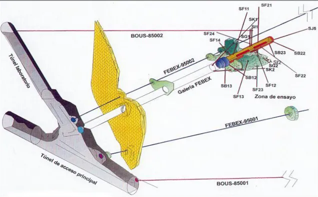
Due to the detailed geological and hydrogeological characterization of the Grimsel Test Site, the comprehensive characterization of the bentonite used to fabricate the engineered barrier and the monitoring performed during the drilling of the FEBEX tunnel as well as during the test, the FEBEX "in situ" test was selected as a modelling exercise for DECOVALEX III. Figure 2.1 shows a perspective of the FEBEX drift and associated boreholes.
The modelling exercise was divided into three parts: Part A – hydro-mechanical modelling of the rock; Part B – thermo-hydro-mechanical modelling of the bentonite; and Part C – thermo-hydro-mechanical modelling of the rock, as described bellow.
2.1.1. Part A: Hydro-Mechanical modelling of the rock
Based on the available geological, hydraulic and mechanical characterization of the Grimsel Test Site as well as on results of hydraulic tests performed on boreholes, a hydro-mechanical model for the zone around the FEBEX tunnel will be prepared. Using this model, changes in water pressure induced by the boring of the FEBEX tunnel as well as the total water flow rate to the excavated tunnel will be required.
Two types of measurements have been selected to develop the modelling exercise: the actual water inflow rates into the FEBEX tunnel and the water pressure response in the vicinity of the tunnel outer perimeter against the tunnel excavation by a Tunnel Boring Machine
Figure 2.1: Layout of FEBEX test and associated boreholes.
Flow measurements into the tunnel provide an integrated variable, controlled by the problem geometry, rock mass fracture pattern, fracture anisotropy, rock matrix permeability and boundary conditions.
The second part asked for a prediction of the transient changes in water pressure recorded at two borehole intervals in the close proximity of the advancing tunnel. The pore water pressure record exhibited a marked transient behaviour when the tunnel face was close to the measuring section of the borehole. This transient behaviour was characterized (in one of the measuring segments) by a rather sharp increase in pressure followed by a slow decay as the tunnel moved away from the measuring section.
This behavior is related to the interaction between rock deformation and water pressure and provides an interesting record of hydro-mechanical interaction in the saturated granitic rock mass. Total water inflow in the test zone (which extends along 17.40 m along tunnel axis) was measured by two techniques (absorbing pads on selected points of the tunnel wall and small gauge measuring of overall leaked water) at different dates in the period January-May 1996, once the tunnel was fully excavated. With this information, it was possible to know the distribution of water input flow on the wall of the FEBEX tunnel.
2.1.2. Part B: Thermo-Hydro-Mechanical Analysis of the Bentonite
Behaviour
Based on the characterization of the bentonite and on the process of test installation, a T-H-M model for the bentonite barrier and the heaters will be prepared. Using this model, the thermo-hydro-mechanical response of the bentonite barrier as a result of the heat released by the heaters will be required. Besides local field variables such as temperature, relative humidity, pore water pressure, stresses and displacements and global variables such as total input power to the heaters will also be required.
The performance of the test and the comparison with modeler’s predictions was based on the following variables:
− The evolution of the total heating power of one of the heaters. The starting time will be the “day 53” which corresponds to the beginning of the automatic control, once the hottest point at the contact between the heater and the bentonite has reached 100ºC. The heating power is a global performance variable which integrates the changing thermal conduction coefficient of the bentonite as the barrier experiences water content changes
− The distribution and evolution of relative humidity of the bentonite barrier. This is a key variable of the experiment since it shows the effects of inner heating and outer hydration from a host rock in a direct manner. Relative humidity variations are the result of water transport processes in liquid and vapour form. Two locations have been selected to show the radial distribution of RH: Section E1 which affects the heater directly, and section H that is a centered section located between the two heaters. The evolution in time of RH is examined in three points at increasing radial distance (in both sections E1 and H): a point close to the heater, “H”, a mid point, “C” and a point close to the granite wall, “G”.
− Temperature. Field information on temperature is vast but it offers limited information on other relevant physical processes and it is essentially controlled by conduction phenomena. Couplings do not affect temperature in a significant way and experience indicates that predictions with most models lead to accurate results. Therefore, the comparison between measurements and temperature predictions will be made in one section (D1) in radial direction.
− Radial stress evolution at some points located at different radial distances in section E2. Measurement errors are often likely in the case of (normal) stresses. In addition, heterogeneous stress distributions and large variations over short distances are possible. Nevertheless the cells installed offered also an interesting field information to the development of swelling-induced stresses inside the barrier
2.1.3. Part C: Thermo-Hydro-Mechanical Analysis of the Rock.
Based on the characterization of the rock massif and on the details of the process of test installation and performance, the rock response in the immediate vicinity of the buffer will be required. The rock is now subjected to the heat released by heaters and by swelling pressures resulting from bentonite hydration. The initial hydrological regime (Part A) is also modified by the presence of the impervious barrier. Temperature, stresses, water pressures and displacements in selected points of the rock will be required.
Several instruments were located, at increasing depth, in the auxiliary boreholes. The length of these radial boreholes does not exceed 15m. Typically, readings are available in three or four positions: close to the tunnel wall (say at 1-3m distance from the origin of the boring, one or two intermediate distances and a distant position (13-14m deep))
Data is available on the following variables: temperature, water pressure in rock, water pressure in packers, stress state and radial displacements.
Water pressure was measured in some boring intervals (a few meters long) separated by packers. The rubber packers were also filled with water and their pressure was maintained and measured externally. Water pressure gauges are located in the measuring area of the FEBEX tunnel. They are connected with the measuring intervals by means of steel tubing.
Three normal components of stress are measured by means of total pressure cells. Four sets of 3 cells were prepared and grouted “in situ” in boreholes SG1 and SG2. Each cell had five sensors oriented in different directions and fixed on a common support 2 m long. Each one of the sensors was a circular steel flat cell. An interpretation of the five readings provides the normal stress components in three directions: radial (with respect to the tunnel axis) (σr), axial (along the direction of tunnel axis) (σx) and circumferential (normal to the radial direction (σθ). Once the sets were in position the borehole was filled with a slightly expansive mortar. Once the mortar was cured, cells were pressurized against the mass of surrounding mortar to guarantee a good initial contact. Note that this procedure provides increments of stress over the moment of cell installation. It will record therefore stress increments due to the performance of the test (temperature effects, modification of pore water pressures, swelling of the bentonite)
Radial displacements were measured by means of borehole extensometers installed in borings SI1 and SI2. They were located close to the position of the stress cells. Each extensometer consists of graphite rods with independent anchoring points located at a depth of 1.0, 3.0 and 7.0 m into the borehole.
2.2. Participating organizations and research teams
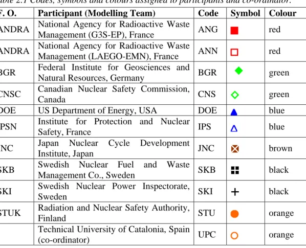
Ten modelling teams, as detailed in Table 2.1, have participated in Task 1 of DECOVALEX III. The acronym of the Founding Organization (F.O.) is also indicated.
In order to organize presentations and comparison reports, a unique 3-character code and a unique symbol was assigned to each participant (Modelling Team). Moreover, a 3-character code and a unique symbol is also assigned to the co-ordinator. The symbol and code of the co-ordinator will be used to identify the experimental data in comparison plots. When possible, a colour (shared by 2 participants) will be used to enhance contrast among curves plotted together. Both the co-ordinator and the participants will use their own code to construct the name of the files to be sent by them. The list with the codes, symbols and colours is given Table 2.1.
Some minor changes in participation took place during the development of the Project. In Part A all the teams included in Table 2.1, except BGR and STUK, participated. In Part B all the working teams, except ANN were active. In Part C, ANN and STUK did not participate.
2.3. Summary of results
2.3.1 Conclusions for Part A
Widely different models for water inflow were used. Some teams (ANN, CNS, and SKB) used uncoupled hydraulic transient models to solve the first part of the exercise, whereas others (ANG, DOE, SKI) used a coupled HM modelling. It does not seem that the mechanical coupling introduces any advantage in this case. In fact, the reason for some of the better predictions (such as SKB calculation) may be associated with previous calibration of the model using other hydraulic data in the same area. Some models describe water circulation in the rock by means of discrete features (tubes, channels such as ANN) equivalent porous medium for different zones (such as DOE,
Table 2.1 Codes, symbols and colours assigned to participants and co-ordinator.
F. O. Participant (Modelling Team) Code Symbol Colour
ANDRA National Agency for Radioactive Waste
Management (G3S-EP), France ANG red ANDRA National Agency for Radioactive Waste
Management (LAEGO-EMN), France ANN red BGR Federal Institute for Geosciences and
Natural Resources, Germany BGR green CNSC Canadian Nuclear Safety Commission,
Canada CNS green
DOE US Department of Energy, USA DOE blue IPSN Institute for Protection and Nuclear
Safety, France IPS blue
JNC Japan Nuclear Cycle Development
Institute, Japan JNC brown
SKB Swedish Nuclear Fuel and Waste
Management Co., Sweden SKB black
SKI Swedish Nuclear Power Inspectorate,
Sweden SKI black
STUK Radiation and Nuclear Safety Authority,
Finland STU orange
Technical University of Catalonia, Spain
(co-ordinator) UPC orange
SKI) and others combine porous medium and discrete fractures (ANG, CNS, SKB). The overall results do not show a particular advantage of a given conceptualisation. Some of the calculations (such as SKI) provide the proportion of flow rates attributed to different origins (matrix, fracture zones). The distribution of measured water inflow rates along the tunnel axis provides a first approximation to the relative proportions of flow through discrete fractures/shear zones and the matrix or distributed flow.
Pore water pressure changes in the vicinity of the tunnel excavation are a direct consequence of changes in the volumetric strain of the rock. Later, pore water pressure dissipations are a consequence of the transition flow towards a new equilibrium, which now has a modified boundary condition (the tunnel surface) in the vicinity. Therefore, fully coupled hydro-mechanical analyses are required to try to capture actual
measurements. In fact, one-way coupling (hydraulic parameters updated as the rock mass deforms) is not capable of reproducing the observed behaviour.
However, the case has demonstrated that even if a fully HM coupled model is used, the difficulties to capture the actual pore pressure of the granitic mass are very high. It was well established that the volumetric behaviour of the rock in the vicinity of the tunnel depends critically on two aspects: the orientation and the intensity of the initial stress field. “In situ” stresses show often a large variability. Field determinations at Grimsel suggest that the major principal stress at the location of the FEBEX tunnel is horizontal (around 30 MPa), whereas the minor principal stress may be considered vertical and defined by geostatic conditions (around 10 MPa). The intermediate principal stress, also horizontal, may reach intermediate (around 15 MPa) values, but remains substantially higher than the vertical stress. It was shown that this particular distribution of initial stress leads to results which are opposite in trend to the actual measurements (dilation of the rock, instead of compression is computed at the P4
locations). In order to match the actual measurements, changes in the intensity of the vertical stress and on the direction of principal horizontal stresses had to be introduced. Moreover, the same initial stress field does not seem to be valid to reproduce results at P3 and P4. It should be added that local conditions at P3 and P4 do not seem to be the same since a more previous zone (which reduces the trend for a rapid initial increase in pore pressure) is present in P3. The finite length of the measuring intervals allows also an easy connectivity between pervious and impervious zones.
2.3.2 Conclusions for Part B
Only a reduced number of modeling teams participated in the blind prediction of Part B. As shown in the comparisons of RH and stress variables only three teams (CNS, SKB and SKI) were able to provide predictions for the full exercise. Modeling teams who used a 1D coupled model (IPS) provided approximate results for cases, which could be approximated by a radial symmetry. This is the case of sections normal to the test axis at the center of each one of the heaters. Models prepared to solve only the Thermo-hydraulic part of the problem (BGR) could not provide predictions for stress development. In some of the models, (BGR, IPS) phase change and vapor transfer was not considered and this limitation hampered the correct reproduction of measured variables. In fact, vapor transfer plays a dominant role in the early stages of the test.
The three fully coupled models (CNS, SKI, and SKB) behaved in general terms in a quite satisfactory manner. They predicted quite accurately the evolution of relative humidities inside the barrier. Stress prediction, however, has proved to be a more difficult task. There is always some concern about the actual reliability of measuring procedures. It appears that the measured radial stresses, which are essentially induced by the progressive hydration of the bentonite, are higher and develop faster than predictions, especially at the end of the considered period.
2.3.3 Conclusions for Part C
As in Part B, only a reduced number of modelling teams provided blind predictions for the rock behavior, once the expansive bentonite barrier was in place. Coupled THM models are also required for this part of the Benchmark although the temperature increase plays a dominant effect on the rock behavior. As it is frequently the case, temperature changes are well reproduced in general terms. Rock water pressures development integrates two separate phenomena: the modification of the hydrogeological regime in the vicinity of the tunnel due to the presence of the barrier and the temperature effects. Temperature effects, in turn, depend on a number of rock properties: rock dilation coefficient, porosity, stiffnes and permeability. The actual development of excess pore pressures are additionally controlled by the rate of temperature change and by the general drainage conditions in the area. It has been suggested that the limited transient reaction of the pore water pressure in the Grimsel host rock is a natural consequence of the high permeability of the rock and, to a lesser extent, of the averaging effect of the measuring interval (a few meters of borehole). The records of packer water pressures have provided interesting complementary evidence of the transient pore water pressure development. Also, the evolution of total stresses, 3 m away from the tunnel wall, shows a transient initial peak which has also been attributed to excess pore water pressure behavior.
Long-term water pressures increase slowly with time in the tunnel immediate vicinity (a few meters). Measured water pressures after 1000 days of test operation are, however, relatively small (1MPa).
Very small incremental displacements were recorded in the 1000-day period (a tenth of a millimetre in 4 and 8m long intervals).
Rock water pressures were reasonably well predicted by three of the research teams (IPS, DOE, and SKI). More limited success was achieved in the prediction of stresses and displacements, with the exception of SKI.
2.4. Summary of scientific achievements of the task
The FEBEX test is one of the few large-scale tests available to gain an integrated perspective of the behaviour of current concepts for nuclear waste disposal in crystalline rock. The comprehensive instrumentation installed in the rock and in the compacted bentonite buffer has yielded vast amounts of data over the past six years. Part of this data, the data corresponding to the first three years of heating, has been used to conduct Task 1 of Decovalex III. The capabilities of a number of finite element codes developed to handle coupled problems in geological and porous media have been evaluated.
For the purposes of the organization of the exercise into specific tasks the Benchmark was divided into three main parts: A: Rock behaviour during the excavation of the FEBEX tunnel, B: Buffer behaviour and C: Rock behaviour during the heating and (partial) hydration of the buffer. This distribution has been maintained in this Report.
Specific conclusions for each of the mentioned parts have been given before. Only a few concluding remarks will be added here:
− The best predictions of the water inflow into the excavated tunnel are found when the hydrogeological model is properly calibrated on the basis of other known flow measurements in the same area. The particular idealization of the rock mass (equivalent porous media, discrete fractures) plays a secondary role
− The development and dissipation of excess pore water pressures in the vicinity of the advancing tunnel (at the time of the FEBEX tunnel excavation) was a clear example of hydro-mechanical interaction. It was concluded that the development of pore pressures was controlled by the initial stress field state, by the rate of excavation and by the permeability and drainage properties of the granite. However, the available information on the intensity and direction of principal stresses in the area was found inconsistent with the actual measurements. The problem posed by this discrepancy was essentially unsettled since a precise determination of the initial stress state in the vicinity of the FEBEX tunnel was not available.
− Predicting the behaviour of the buffer under the combined heating and wetting actions requires a fully coupled THM formulation, which incorporates all the necessary physical processes controlling the bentonite behaviour. Only a partial set of codes could offer the required features. Particularly relevant to predict the early stages of heating was the inclusion of phase changes of water and the vapour transport. Codes incorporating these features were capable of making good predictions. It should be added that the FEBEX in situ test benefits from a comprehensive experimental information on compacted bentonite properties derived from a large variety of laboratory tests on samples and on small-scale hydration and heating cells.
− It has been shown that the hydration of the bentonite buffer was essentially independent of the heterogeneous nature of the rock hydraulic conductivity features. This is explained by the fact that the rock matrix permeability is higher than the saturated bentonite permeability. Some 3D analyses performed, where the heterogeneous permeability features of the rock have been included, tend to support also this conclusion.
− The heating of the rock resulted in a significant increase in rock stresses in the vicinity of the FEBEX tunnel. Water pressures remained however essentially unchanged. The relatively high rock permeability explains the absence of significant pore water pressure transients. Only one of the participating modelling teams was capable of achieving a consistent prediction of all the measured variables in the rock: temperature, water pressures, rock stresses and radial displacements
2.5. Lessons learned and outstanding issues
The previous section summarizes some of the most relevant findings of the project. They have a specific character. It is possible also to adopt a more general perspective to evaluate the project. As a general introductory statement, the entire project was a learning process experience for all the involved participants. Some of the physical explanations found for specific measurements (i.e. the development of pore water pressures in the granite when the Febex tunnel was excavated) or the progressive improvement of THM codes are aspects of this process.
A second general comment concerns the character of “blind prediction”, which was a pre-requisite for the organization of the work. It turned out that a true prediction (which is, by nature, blind) is difficult to make even if a highly controlled and documented case record (such as Febex) is chosen for benchmark exercises. It is a fact that “predictions” become more and more accurate as the answer to the problem, i.e. the real field measurements, are made available to modellers.
Concerning the modelling philosophy adopted by different groups, it is interesting to realize that a good “a priori” understanding of the relevant physical phenomena at play becomes perhaps the most important item to achieve good results. In particular, decisions concerning the relevant couplings in a particular problem, are a key issue in the modelling exercise. These decisions are not always clear or obvious, and they require the appropriate technical and scientific background. As an illustration of these comments, the following couplings, or main physical phenomena, have been identified as the most relevant ones for the three cases solved under Task 1. Failure to consider them precludes the correct simulation of some features of the observed behaviour. Part A (Specially the prediction of pore water pressure development)
− Full hydro-mechanical coupling
− Due consideration to a general three-dimensional initial stress field
− Modelling in detail the rate of geometry changes (progress of tunnelling in time) Part B
− Phase changes between liquid water and water vapour − Concentration-driven vapour flux
− Saturation dependent water permeability and thermal conductivity − Suction-induced deformations
Part C
− Thermal dilation of water and skeleton. (The second provides the main reason for stress development and the difference between water and skeleton dilation is the origin of heat induced pore water pressures).
− Full hydro-mechanical coupling
In a reverse sense, a good understanding of the physical processes may lead to the selection of appropriate simplifications. In parallel to the previous list, the following set of aspects was found of minor relevance in the Febex case:
− The structure of the granite rock played a negligible influence on the hydration of the bentonite buffer. This was explained as a consequence of the difference in saturated permeability of the bentonite and the rock matrix
− The gas pressure may be safely assumed to be constant, due to the high gas permeability
− Plastification of the bentonite does not seem to be an issue because of the high − confinement provided by the rigid granite. Simple elastic models, provided that suction effects are incorporated may suffice.
− The heat-driven water flow in the rock is not affected by the heterogeneous nature of the rock because the characteristic heating time is larger than the characteristic time for dissipations of pore water pressures.
A number of unresolved, or insufficiently known aspects, remained at the end of the work performed. The following may be mentioned:
− The behaviour of the system at long times. This comment refers to issues such as saturation times, chemical effects and corrosion effects. These problems were not specifically discussed in Decovalex III, although they are part of the general design problem addressed by Febex.
− The effect of the change of scale implied by a real repository where many tunnels carrying waste are closely located in a large disposal area. Same comment as above.
− The difficulty to match with calculations the mechanical response of the buffer (stresses, displacements). The blocky nature of the buffer was not considered by any of the modelling teams.
Concerning the methodological and numerical approaches followed by different groups two additional general comments may be made:
− Numerical analysis performed could be divided into two types: single program fully coupled or a combination, via a staggered approach, of codes solving partial problems. Groups falling in the second category found more difficulties to reproduce adequately the observed phenomena.
− Very few participants took advantage of the small and medium-scale laboratory tests performed on the bentonite in order to derive model parameters. These tests are considered as especially relevant to derive, using backanalysis techniques, accurate material parameters, even if different constitutive models are employed.
3 Executive summary – Task 2
3.1 Introduction
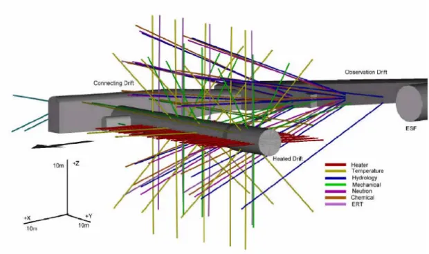
The Drift Scale Test (DST) in Yucca Mountain in Nevada, USA is a large scale, long term field thermal test being conducted for the United States Department of Energy (DOE). The heating phase of the DST, an integral part of DOE’s program of site characterization at Yucca Mountain to assess whether the mountain is suitable site for a repository for the disposal of high level nuclear waste (HLW) and spent nuclear fuel (SNF), was initiated in December 1997. Heating was terminated in January 2002 ushering in the cooling phase of the test that is expected to continue for four years. The overarching objective of the DST is to study coupled thermal, hydrological, mechanical, and chemical processes caused by the decay heat from HLW and SNF emplaced in an underground geologic repository. The layout of the DST est is shown in Fig. 3.1.
Figure 3.1: Perspective of DST Block Showing Multiple Boreholes to House Heaters and Sensors
The DST consists of a 5 m diameter, 47.5 m long drift heated by nine cylindrical electric heaters placed on the floor. Each heater, 1.7 m diameter and 4.6 m long, is capable of generating a maximum of 15 kW. Additional heating is applied by 50 rod heaters, referred to as “wing heaters”, emplaced in horizontal boreholes drilled into either side wall of the drift (Figure 1). The drift cross-section and the cylindrical heaters are approximately the sizes of emplacement drifts and waste packages, respectively, being considered for the proposed repository. The wing heaters are employed to simulate the heat that would come from adjoining drifts in the repository, and thus to provide better test boundary conditions. Each wing heater, 10m long, has two distinct segments capable of generating 1145 W and 1719 W. An Access/Observation drift
(AOD) parallel to the Heated Drift (HD) and an orthogonal Connecting Drift (CD) delineate the periphery of the test block (Figure 1). As shown in Figure 1, a large number of boreholes drilled from the drifts into the test block house the heaters, instruments, and sensors for the test.
3.2. Problem definition and work organization
In 1998 the DST was included as a test case in the then ensuing DECOVALEX III project, the Task 2. Task 2 of DECOVALEX III organized around the DST had four sub-tasks: Task 2A, Task 2B, Task 2C and Task 2D. Task 2A was to mathematically simulate and study the thermal-hydrological (TH) responses of the rock mass in the DST. Tasks 2B and 2C were to model and analyze the thermal-hydrologic-mechanical (THM) and thermal-mechanical (TM) processes of the rock mass in the test. Task 2C differed from 2B in that measured temperatures were the input in simulating the TM response while predicted or calculated temperatures were the input in 2B. Task 2D was to study the thermal-hydrologic-chemical (THC) response.
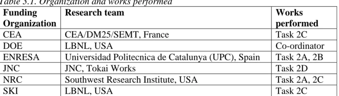
Table 3.1. Organization and works performed
Funding Organization
Research team Works performed
CEA CEA/DM25/SEMT, France Task 2C
DOE LBNL, USA Co-ordinator
ENRESA Universidad Politecnica de Catalunya (UPC), Spain Task 2A, 2B
JNC JNC, Tokai Works Task 2D
NRC Southwest Research Institute, USA Task 2A, 2C
SKI LBNL, USA Task 2C
3.3. Modeling approaches
To simulate the thermal-hydrological (TH) response of the DST for Task 2A the ENRESA/UPC research team employed the finite element code CODE_BRIGHT which solves mass conservation equation (air and water), energy conservation equation in non-isothermal state, and momentum balance equation for mechanical equilibrium to predict the TH conditions. Initially, their model used a single equivalent porosity and permeability structure to represent the fractured tuff in the DST block (Datta, 2002). Later the ENRESA/UPC team used double porosity and double permeability structure to represent the co-located fracture medium and the matrix medium (Datta et al, 2003). The NRC/SWRI researchers used the multiphase simulator MULTIFLO to perform Task 2A TH modeling. Their model involved the dual continuum model (DCM) formulation that is similar to the dual permeability model (DKM) used by the DOE researchers. Both the DOE and NRC researchers invoked the active fracture model for unsaturated flow through fractured rock proposed by Liu et al (1998) to ensure realistic fracture-matrix interaction. The DOE research team used the TOUGH2 code to perform the TH modeling of the DST (Pruess et al., 1999).
For Task 2B, SKI researcher and later DOE researcher performed coupled thermal-hydrological-mechanical (THM) analysis of the DST with the TOUGH-FLAC code which is a simulator based on coupling of two established computer codes: TOUGH2
(Pruess et al. 1999) and FLAC3D (Itasca Consulting Group, 1997). TOUGH-FLAC simulation captures the effect of stress changes on hydraulic properties based on a conceptual model of highly fractured rock mass containing three orthogonal fracture sets. Porosity correction factors and permeability correction factors are calculated from the initial and current apertures assuming equally spaced fractures and adopting the parallel plate fracture flow model. The ENRESA/UPC researchers performed their 2B analysis by CODE_BRIGHT that allows permeability changes to be calculated based on changes in porosity due to stress changes.
For Task 2C, both the CEA and NRC researchers used measured temperature profiles as the thermal input to model the thermal-mechanical process to predict displacements in rock. The NRC team performed a continuum analysis using the FLAC code. The CEA team also performed continuum analysis using the code Castem2000 (Verpeaux et al., 1989).
The works performed for Task 2B and 2C was reported in ( Datta et al., 2004a). For Task 2D, the JNC team performed coupled THC simulation of the DST employing the THM code THAMES (Ito et al., 2003; Ohinishi et al. 1985; Chijimatsu et al. 2000), mass transport code Dtransu (Nishigaki et al. 2001) and the geochemical code PHREEQE (Parkhurst et al. 1980). These three codes are controlled by the coupling system COUPLYS which can exchange common data between the three codes and can synchronize each code in order. The DOE researchers used the TOUGHREACT code (Xu et al., 2003) to model the THC processes in the DST adopting the dual permeability method to capture separate yet interacting processes in fractures and matrix.
Simulations of THC processes included coupling between heat, water, and vapor flow; aqueous and gaseous species transport; kinetic and equilibrium mineral-water reactions; and feedback of mineral precipitation and dissolution on porosity, permeability, and capillary pressure.
The work performed for Task 2D was reported in (Datta et al, 2004b).
3.4. Scientific achievements
The DST confirmed that the heat transfer process in the Yucca Mountain fractured tuff is conduction dominated, although pore water plays an important role, especially in the sub-boiling regime. Vaporized water travels away from the heat via fractures and condenses in cooler regions, thereby filling fractures and lowering the permeability. Various conceptual models were evaluated by comparing simulated and measured temperatures. The dual continuum model (fracture and matrix) and active fracture concept reflecting actual heat load yielded the best agreement.
The effect of dimensionality (i.e., 2D versus 3D) on temperature was evaluated. A maximum reduction of temperature of about 100C near the wing heaters was calculated after four years of heating when a 3D model was used compared to a 2D model. The TH calculations indicate that it is possible to choose appropriate hydrological parameters to obtain a distribution of saturation similar to the ones measured in the field.
The good agreement between simulated and measured air permeability indicates that the adopted conceptual model is sound, and that the model coupling stress with permeability is appropriate for predicting TM-induced permeability changes at Yucca Mountain.
Task 2 researchers presented seven papers based on their DECOVALEX III project work at the GeoProc 2003 conference held at the Royal Institute of Technology in
Stockholm, Sweden in October 2003 (Datta et al., 2003; Rutqvist et al., 2003; Hsiung et al., 2003; Green and Painter, 2003; Olivella et al., 2003; Millard & Rutqvist, 2003). More papers will be submitted for a forthcoming Special Issue of the International Journal of Rock Mechanics and Mining Sciences devoted to achievements in DECOVALEX III/BENCHPAR projects.
3.5. Lessons learned and outstanding issues
The DST is a large and complex field test in which a multitude of measurements were made, and its realistic simulation needs multidiscipline approaches with multiple research teams with different concepts and approaches so as to achieve more in-depth understanding to the coupled THMC processes involved. DECOVALEX III researchers studying the DST for Task 2 performed well in their individual works, but more concentrated efforts with more teams involved is needed for further studies, helped with more active coordinating.
Although the effects of the chemical processes have been investigated in-depth by DOE over the years, the works performed in the Task2 for this effect is not adequate for furthering the scientific understanding due simply the two few numbers of teams involved.
The presence of fractures in the DST site and the long periods of heating-cooling phases of the test may cause residual and long-term variations in physio-chemical properties of the fractured tuff, due to the irreversibility of the coupled THMC processes, for example the residual fracture deformation and its impact on permanent change sin permeability of the near-field. Such residual and permanent changes will be important factors affecting design and performances of post-closure monitoring works and final safety assessment. Study on these effects are not considered in Task 2 of the DECOVALEX III project, but is an important outstanding issue for further research.
4 Executive summary - BMT1, Task 3
4.1. General definition of the problem
In the definition of BMT1, it was proposed that scoping calculations be performed in order to estimate how T-H-M processes can influence the flow pattern as well as the structural integrity of the geological and engineered barriers in the near-field of a typical repository.
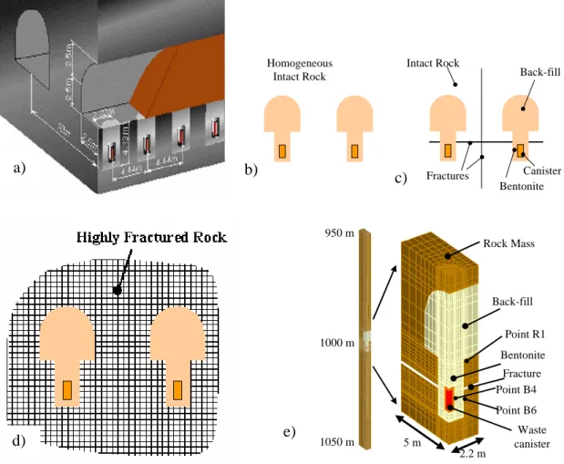
The definition of BMT1 is based on a hypothetical nuclear waste repository in a granitic rock formation at a depth of 1000 m. The typical repository being assessed has rather composite features: it is based on a Japanese conceptual design, the buffer is the same pure bentonite used in the Kamaishi THM experiment in Japan (Fig. 4.1), but the rock mass properties in term of strength and permeability are based on typical Canadian Shield’s data. The conceptual design of the repository is illustrated in Figure 4.2a (JNC, 2000). The centreline distance between adjacent tunnels is 10 m and the centreline distance between adjacent depository holes for the wastes is 4.44 m. The depth of each depository hole is 4.13 m and the diameter is 2.22 m. The overpack (canister) for radioactive wastes would be emplaced into the depository hole, and a bentonite buffer material would be compacted around the overpack. The tunnels would also be backfilled with a mixture of gravel and clay. The Performance Assessment analyst in order to assess nuclide transport through the engineered and geological barriers may require feedback on the following key points:
1. What is the temperature evolution in the near-field? 2. How long would it take for the buffer to re-saturate?
3. What are the stresses on the overpack and in the buffer? Will they be structurally stable?
4. How will the permeability and the flow field of the rock mass in the near-field evolve?
5. Is there a potential for rock mass failure in the near-field?
6. What are the uncertainties related to the answers to the above questions, taking into account the variability in the properties of the rock mass?
The BMT1 objective is to answer the above questions through THM simulations of the hypothetical repository. This summary provides an overall presentation of the problem based on three progress reports (Jing and Nguyen, 2001, 2003a and 2003b).
4.2. Implementation steps
In order to address the above points, the research teams will perform T-H-M analyses and adopt the following three-step strategy, which will constitute separate subtasks of BMT1:
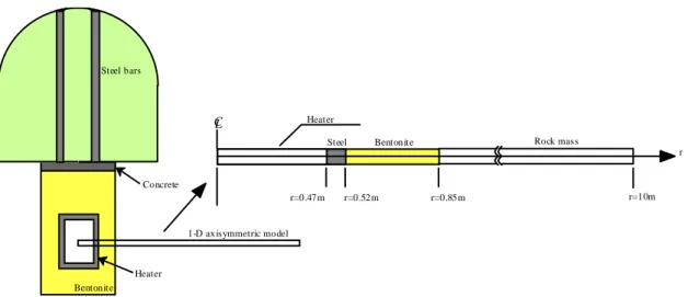
Step 1 (subtask BMT1A). Calibration of the computer codes with a reference T-H-M experiment with realistic rock mass conditions and measured outputs of thermal, hydraulic and mechanical variables: The reference experiment chosen for BMT1 is the Kamaishi in-situ experiment at Kamaishi Mine, Japan, performed at the 550 m-Level
1-D axisymmetric model Steel bars Concrete Heater Bentonite Heater
Bentonite Rock mass
r=0.52m r=0.85m r=10m
CL
r r=0.47m
Steel
Figure 4.1: Near-field T-H-M experiment with one single heater- the simplified model geometry for BMT1A.
gallery of the experimental site, as illustrated in Fig.4.1. The objective of the BMT1A subtask is to validate the numerical approaches, computer codes and material models, so that the teams simulating tools are at a comparable level of maturity and sophistication. Step 2 (Subtask BMT1B). Use of the calibrated codes to perform scoping calculations, considering varying degrees of THM coupling, for the generic repository design shown in Fig. 4.2. To simplify the calculation process and focus on the physics of the problems instead of computational efforts, the geometry of the problem, especially regarding the geometry of the fractures, is greatly simplified to regular fracture geometries. In subtaskBMT1B, the rock is considered to be homogeneous without any explicitly represented fractures. However, different permeability values are considered. The aim is to identify the coupling mechanisms of importance for construction, performance and safety of the repository.
Step3 (Subtask BMT1-C). Perform scoping calculations with different coupling combinations for the case where a horizontal fracture intersects the deposition hole and a vertical fracture zone divides two adjacent deposition tunnel/hole system (Fig. 4.2c). A hydrostatic condition is applied along the vertical fracture as a hydraulic boundary condition. In addition to this definition, the SKI/KTH team performed an additional calculation of highly fractured rock mass with two orthogonal sets of fractures with a spacing of 0.5 m )Fig. 4.2d). Figure 4.2e shows a typical FEM model for BMT1C. The aim is the same as that of BMT1B but with the additional influence of explicit fractures. It was identified from the start that the focus of the analyses in B and BMT1-C should be on the following output results, deemed to have a strong influence on the long term safety and performance of the repository:
1. The maximal temperature created by the thermal loading from the emplaced wastes
2. The time for re-saturation of the buffer
3. The maximal swelling stress developed in the buffer 4. The structural integrity of the rock mass
5. The permeability evolution in the rock mass
The combinations of coupling mechanisms and their effects on the above output could be summarized in an interaction matrix shown in Table 4.1. The research teams were asked to perform their calculations considering the coupling combinations shown in the matrix, and compare the output results between the coupling combinations.
Fractures Intact Rock Homogeneous
Intact Rock Back-fill
Canister Bentonite 1050 m 950 m 1000 m Rock Mass Back-fill Bentonite Fracture Waste canister 5 m 2.2 m Point B4 Point R1 Point B6
Figure 4.2: Generic design of a hypothetical repository (a), concept of BMt1B (b), concept of BMt1C (c), Additional case studied by the KTH/SKI team (d) and a typical FEM model for BMT1C (e).
Table 4.1. Comparison matrix of for different degree of THM coupling (T-temperature,
σ-stress, k-permeability, p-pressure, θ-water content)
Output
T M H H-M T-H T-M T-H-M
T-evolution Y N/A N/A N/A Y Y Y
σ-evolution N/A Y N/A Y N/A Y Y
k-evolution N/A N/A N/A Y Y N/A Y
p-evolution N/A N/A Y Y Y N/A Y
θ-evolution N/A Y Y Y Y N/A Y
(Y: Output to be calculated N/A: Not applicable.)
4.3. Work organization and physical processes
concerned
Six research teams participated in BMT1, using either finite element (FEM) or finite difference(FDM) methods , as shown in Table 4.2.
The physical processes considered in the BMT1 include mainly:
a) b)
c)
Table 4.2. The research teams and their approaches for BMT1
Team FO Method Code(s) Tasks
CEA IPSN FEM (3D) Castem 2000 BMT1A, 1B & 1C CNSC CNSC FEM (3D) FRACON BMT1A, 1B & 1C INERIS ANDRA FDM (3D) FLAC BMT1A
JNC JNC FEM (3D) THAMES BMT1A, 1B & 1C ISEB-ZAG BGR FEM (3D) RF/RM BMT1B
KTH SKI FEM (3D) ROCMAS BMT1A, 1B & 1C
Water flow in partially and/or fully saturated buffer and rock, in both liquid and gas states, especially the thermally driven water moisture diffusion process;
Heat conduction and convection in buffer and rock;
Stress, deformation and failure of rock using the Hoek-Brown failure criterion;
Variation of swelling pressure, water content and relative permeability fields in buffer due to coupled THM processes as listed above;
4.4. Summary on scientific achievements
4.4.1. Achievement from BMT1A
A number of improvements to the modelling of the Kamaishi Mine heater test were suggested and tested in this study, using a simplified axisymmetric model of the heater test as shown in Fig. 4.1. Although the model geometry is much simplified compared to the field test conditions, improved simulation of the general THM responses were obtained, as compared with the Task 2C results of DECOVALEX II. The measures taken for improvement were:
Parameter changes (reduced rock mass permeability and rock mass thermal expansion by the KTH/SKI team, and increased thermal expansion coefficient and reduced swelling pressure constant of the buffer by JNC team)
Inclusion of the sealing of rock fractures by penetrating bentonite by the KTH/SKI team, which can explain the uniform (axisymmetric) wetting of the bentonite.
An improved swelling/shrinking strain function combined with an increased thermal expansion of the bentonite giving a good match of the mechanical (stress, strain) behavior of the buffer by the KTH/SKI team.
Uses of higher Young’s modulus and Poisson’s ratio of the bentonite near the heater, and a “sealed” layer of rock around the bentonite by the CNSC team. As a results of the above measures, the results from the simplified axisymmetric model used in the re-evaluation of the Kamaishi mine experiment showed general improvement over the original models used in the prediction phase during the DECOVALEX II project, especially in the following aspects:
Calculated values of temperature agree very well with the experimental values, for all teams.
Generally improved stress and strain behaviour in the bentonite, at least qualitatively though, with the measured results.
The water content near the heater (at point 1) is relatively well predicted by all teams, although the saturation front at the bentonite/rock interface are still
predicted to advance much faster than in reality.
In general, the mechanical behaviour of the buffer is complex with forces contributing from shrinking/swelling in all part of the bentonite, external stress from the thermal expansion of the heater and rock, and internal thermal expansion of the bentonite itself. However, a reasonable prediction of the mechanical behaviour can be done if all relevant bentonite properties are known from laboratory tests.
4.4.2. Achievements from BMT1B
The teams successfully performed required scoping calculations and important conclusions were drawn regarding the importance of THM coupling processes for design, construction, performance and safety of the repository. In order to assess the importance of different coupling mechanisms and their combined effects, the research teams have considered different degree of complexity of the coupling mechanisms as shown in Table 4.1. From the modelling results, it was identified that the initial rock mass permeability is a key parameter.
For the typical repository considered in BMT1-B, only the fully THM analysis predicted some localized rock mass failure around the deposition holes, which might in turn result in a zone of higher permeability. Other important effects of THM and HM coupling would be on the stresses developed in the buffer, which would be transferred to the canister and influence its mechanical integrity. From a safety point of view, engineering measures could be easily carried out to minimize these effects. From the results of the BMT1B, it appears that from a technical point of view the effect of coupling will be either short lived (several decades to 100 years) and would not impact on long term (thousands to hundred of thousand years) safety issues, or could be rectified by adequate design and operation methodology (e.g. avoid over-cooling the galleries in the Japanese context). The influence of the host rock properties (e.g. permeability) on the long-term safety seems to be much more important than coupling effects, since one has much less control over these properties. However, a fully coupled approach is necessary to help design and construction strategies and to interpret monitoring data that would be collected in the first few decades after the repository closure. Coupled processes would prevail during that monitoring period and an adequate interpretation of the monitoring data is essential in building confidence and demonstrating to the stakeholders that the repository is behaving in a predictable manner.
4.4.3. Achievements from BMT1C
This analysis aimed to evaluate the impact of THM couplings on the performance of a repository located in sparsely fractured rocks. The results of this analysis can be summarised as follows:
•
Temperature evolution (T process): no significant effect of HM coupling on heat transfer processes and heat conduction dominates.•
Resaturation of the buffer (H process): affected by heat transfer process but not significantly by the mechanical process.•
Pressure evolution in the buffer (M process): strongly affected by the hydraulic process and slightly affected by the heat transfer.•
Mechanical integrity of the near-field rock (M process): strongly affected by the coupled TH coupling.It is clear that the temperature can be predicted accurately without consideration of
coupling to hydraulic and mechanical processes since heat convection plays a minor role in temperature evolution and the conversion of the mechanical work (dissipated energy) is not significant at all. On the other hand, it is also clear that the mechanical behaviour (mainly the evolution of stress in the buffer-rock system) cannot be appropriately predicted without consideration of the effects of fluid pressure and temperature. However, it is not clear from the BMT1 analyses whether the hydraulic behaviour (for example re-saturation of the buffer and radioactive nuclide transport) can be significantly impacted by T and M processes. For the parameter set adopted in this analysis, the re-saturation time is slightly impacted by the effect of temperature whereas the mechanically induced changes in permeability (of the rock or the buffer????) do not significantly impact the re-saturation process.
The general results of the impact of various THM couplings for sparsely fractured rocks are in line with those of a homogeneous rock. The main difference is that the hydraulic conducting fractures provide an additional water supply path that prevents desaturation of the rock and accelerates the buffer re-saturation process.
4.4.4. Generated Publications
Besides the progress reports in the reference list at the end of this summary, additional international publications have been generated by the research teams involved with BMT1 (Chijimatsu et al.,2003; Kohlmeier et al., 2003; de Jonge et al., 2003; Millard et al., 2003; Rutqvist et al., 2003 and Nguyen et al., 2003). They are papers published in the proceedings of the international Conference of GeoProc 2003 (Stephansson et al., 2003).
4.5. Lessons learned and outstanding issues
The BMT1 is a comprehensive numerical Bench-Mark Test problem considering coupled THM processes in the near-field buffer and rocks of a hypothetical repository. The special features of buffer re-saturation and mechanical integrity of the repository are considered for the first time in the DECOVALEX I, II and III project series. Through iterative verification against the results from the in-situ THM experiments at the Kamaishi Mine, significant progress have been achieved in the development of robust mathematical and numerical models. The computer codes applied to the BMT1 tasks have achieved significant upgrading for the modelling of complex coupled THM processes in buffer materials and rock masses. Thus, the codes become more reliable tools to aid in the design, construction, performance and safety assessments of nuclear waste repositories.
On the other hand, further improvement in both the models and the hypothetical case definition is always desirable. The main lessons learned and the outstanding issues from the BMT1 problem series may be summarized as follows: