www.afm-journal.de
π-Conjugation Enables Ultra-High Rate Capabilities
and Cycling Stabilities in Phenothiazine Copolymers
as Cathode-Active Battery Materials
Pascal Acker, Luisa Rzesny, Cleber F. N. Marchiori, C. Moyses Araujo, and Birgit Esser*
In recent years, organic battery cathode materials have emerged as an attractive alternative to metal oxide–based cathodes. Organic redox polymers that can be reversibly oxidized are particularly promising. A drawback, however, often is their limited cycling stability and rate performance in a high voltage range of more than 3.4 V versus Li/Li+. Herein, a conjugated copolymer design with phenothiazine as a redox-active group and a bithiophene co-monomer is presented, enabling ultra-high rate capability and cycling stability. After 30 000 cycles at a 100C rate, >97% of the initial capacity is retained. The composite electrodes feature defined discharge potentials at 3.6 V versus Li/Li+ due to the presence of separated phenothiazine redox centers. The semiconducting nature of the polymer allows for fast charge transport in the composite electrode at a high mass loading of 60 wt%. A comparison with three structurally related polymers demonstrates that changing the size, amount, or nature of the side groups leads to a reduced cell performance. This conjugated copolymer design can be used in the development of advanced redox polymers for batteries.
DOI: 10.1002/adfm.201906436 P. Acker, L. Rzesny, Prof. B. Esser Institute for Organic Chemistry University of Freiburg
Albertstraße 21, 79104 Freiburg, Germany E-mail: besser@oc.uni-freiburg.de Prof. B. Esser
Freiburg Materials Research Center University of Freiburg
Stefan-Meier-Str. 21, 79104 Freiburg, Germany
cathode materials[15–18] with reported
cell voltages of up to 4.1 V versus lithium as anode.[19] Mainly, two classes
of polymers have been considered, as shown in Figure 1: aliphatic redox poly-mers and conducting polypoly-mers. In the former, redox-active groups are covalently attached to an aliphatic polymer back-bone, which serves to ensure their insolu-bility in battery electrolytes.[4,17,18] Typical
examples are polymers containing stable nitroxyl radicals in the side group.[20–22]
These polymers are usually electronically insulating, and charge transport between redox-active side groups can only occur through hopping processes or self-exchange between redox centers, which limits their rate capability. An advantage of these polymers is that they feature a stable redox potential, regardless of the charging state of the battery.
Conducting polymers, on the other hand, possess intrinsic conductivity in the doped state, but sloping charge/discharge potentials due to the extensive delocalization of charges. Furthermore, often times only low doping levels are accessible in a reversible fashion.[4,15,23,24] We herein present a combination of the
ben-efits of both designs by using π-conjugated redox polymers P1 and P2 as cathode-active materials in a lithium organic bat-tery (Figure 1). The resulting polymer-based composite elec-trodes of P1a and P2 possessed both stable charge/discharge
Organic Batteries
© 2019 The Authors. Published by WILEY-VCH Verlag GmbH & Co. KGaA, Weinheim. This is an open access article under the terms of the Creative Commons Attribution License, which permits use, distribution and re-production in any medium, provided the original work is properly cited.
Prof. B. Esser
Cluster of Excellence livMatS @ FIT—Freiburg Center for Interactive Materials and Bioinspired Technologies University of Freiburg
Georges-Köhler-Allee 105, 79110 Freiburg, Germany Dr. C. F. N. Marchiori, Prof. C. M. Araujo
Materials Theory Division
Department of Physics and Astronomy Uppsala University
Box 516, 75120 Uppsala, Sweden Dr. C. F. N. Marchiori
Department of Chemistry—Ångström Laboratory Uppsala University
Box 538, 75121 Uppsala, Sweden The ORCID identification number(s) for the author(s) of this article
can be found under https://doi.org/10.1002/adfm.201906436.
1. Introduction
Organic cathode materials have been identified as promising
candidates for next-generation battery systems.[1–12] Their
advantages include a high structural diversity and design flexibility as well as a low toxicity. In addition, they are acces-sible from less-limited resources compared to their inorganic counterparts.[13,14] Redox polymers are among the best organic
potentials due to the well-defined phenothiazine redox centers as well as ultra-high rate capability, and long-term cycling sta-bility at 100C rate in the case of P1a, because of the
semicon-ducting nature of the polymers. With 3.6 V versus Li/Li+, the
discharge potentials in composite electrodes lay close to the
operation potential of commercial Li-ion battery cathodes.[25]
In addition, they contained a high mass-loading of 60 wt% active material. P1b–d served to elucidate the influence of side chains on the battery performance of the polymers, and P3 was used to assess the influence of π-conjugation (Figure 1).
The concept of a π-conjugated redox polymer as battery electrode material has been demonstrated before using the well-known n-type NDI-bithiophene copolymer P(NDI2OD-T2) with a discharge potential of about 2.4 V versus Li/ Li+,[26] as well as the corresponding fluorene copolymer.[27]
In this work, a p-type conjugated polymer with phenothia-zine was chosen based on its reversible oxidation chemistry, high oxidation potential of 3.6 V versus Li/Li+, and excellent
performance in battery cathode materials.[28–33] We recently
demonstrated high cycling stabilities at 10C rate using poly(3-vinyl-N-methyl-phenothiazine) due to supramolecular hole-transport.[28,29,34] In order to separate the redox-active
phenothiazine moieties and to allow for good hole conduc-tivity, we used bithiophene and fluorene as comonomers in
P1 and P2, respectively. An aryl ether group was chosen as
substituent R to obtain highly reversible oxidation processes
of the phenothiazine group upon oxidation,[35] and alkyl
groups were attached in P1a, P2, and P3 to ensure solubility of the polymers for purification and preparation of composite electrodes. Conjugated copolymers of phenothiazine with flu-orene and bithiophene have been reported before for use in organic light-emitting diodes or photovoltaic cells,[36–41] but
not for battery applications.
2. Results and Discussion
2.1. Comparison of Bithiophene and Fluorene Copolymers and Influence of Conjugation
2.1.1. Synthesis of Polymers P1a, P2, and P3
The required phenothiazine monomer 1 was synthesized in three steps starting from phenothiazine (2, Scheme 1). Buchwald–Hartwig reaction allowed introducing the aryl ether moiety on the nitrogen atom, followed by twofold bromina-tion to yield 3. The bromo substituents were then replaced by boronic ester moieties to obtain 1. Suzuki–Miyaura poly-condensations of phenothiazine monomer 1 with the cor-responding dibromides 4–6 yielded polymers P1a, P2, and
P3, respectively (Scheme 1). 4[42] and 5[43] were synthesized
according to the literature, and the synthesis of 6 can be found in Supporting Information. In order to obtain P1–P3 with high molecular weights and in high yields, we performed an extensive optimization of reaction conditions, in particular concerning the catalyst and reaction mode (see Supporting Information for details). High molecular weights are impor-tant to ensure insolubility of the polymers in the battery electrolyte. Tris(dibenzylideneacetone)dipalladium with the ligand SPhos and sodium hydroxide as base in toluene/ water (3/1) with Aliquat 336 as phase-transfer catalyst was the method of choice. We furthermore found that polymerization in a microwave synthesizer using SPS mode provided supe-rior results and shorter reaction times compared to oil bath heating.
We assessed the thermal stability of P1a, P2, and P3 using thermal gravimetric analyses. All three polymers possessed high decomposition temperatures above 405 °C (P1a), 402 °C (P2), and 402 °C (P3) (onset of decomposition in air, see Figures S59 and S60, Supporting Information).
2.1.2. Electrochemical and Optical Properties of Polymers P1a, P2, and P3
Cyclic voltammetry (CV) measurements and UV–vis absorp-tion and emission spectroscopy provided informaabsorp-tion about the electrochemical and optical properties of P1a, P2, and P3, as summarized in Table 1. In solution, P1a, P2, and P3 fea-tured reversible oxidations at half-wave potentials of 0.20, 0.23, and 0.13 V versus Fc/Fc+, respectively (see Figure 2a–c). The
second oxidations of the phenothiazine units in P1a, P2, and
P3 occurred at 0.77, 0.90, and 0.69 V versus Fc/Fc+, respectively
(see Figure S45, Supporting Information). P1a showed two fur-ther oxidation waves at potentials of 0.69 and 0.92 V versus Fc/ Fc+, likely because of the bithiophene units.
Figure 1. Combining defined redox centers, as present in aliphatic redox polymers, with a conjugated polymer backbone leads to π-conjugated redox polymers P1a–d and P2 with well-defined oxidation potentials and hole transport along the polymer backbone. P3 with broken conjugation served for comparison.
The absorption spectra of P1a, P2, and P3 (see Sup-porting Information) displayed two main bands with maxima between 307 and 410 nm (Table 1). The optical band gaps lay between 2.44 and 2.66 eV. All three polymers were fluorescent with emission maxima of 519, 483, and 474 nm for P1a, P2, and P3, respectively (see Table 1 and Figure S56, Supporting Information).
2.1.3. Electrochemical Testing of Polymers P1a, P2, and P3 as Cathode-Active Battery Materials
For the investigation of P1a, P2, and P3 as cathode-active mate-rials in batteries, we fabricated composite electrodes containing a high ratio of 60 wt% polymer, 35 wt% Super C65 as conductive additive, and 5 wt% PVdF binder. Metallic lithium was used as
the counter and reference electrode and 1 m LiPF6 in EC:DMC
1:1 as electrolyte. Scanning electron microscopic (SEM) meas-urements showed that the porous, percolated network structure of the carbon black Super C65 was maintained in the composite electrodes. The surface of the carbon network was evenly coated with the polymers, as confirmed by energy-dispersive X-ray spec-troscopy (EDS) measurements (see Figures S62–S70, Supporting
Information, for SEM and EDS images). As seen from the CVs (Figure 2d,e), the oxidations of P1a, P2, and P3 in com-posite electrodes occurred at potentials of 3.68, 3.70, and 3.59 V versus Li/Li+, respectively, around 0.2 V higher than would be
expected from the values in solution (assuming 3.25 V[45] for
Fc/Fc+ versus Li/Li+). For P1a and P2, the oxidation peaks were
narrow, indicating well-defined, faradaic redox processes, while
P3 showed broader peaks. This stands in contrast to polymers
solely containing phenothiazine units with broad oxidation peaks.[31,46,47] At 3.9/4.0 V versus Li/Li+, the second oxidations
started setting in, visible in the cathodic scans (see Figure S45, Supporting Information).
Constant current cycling measurements at 1C rate
(Figure 3a–d) in the range of 3.2–3.9 V versus Li/Li+ showed
stable cycling behavior. All three polymers reached a value close to their theoretical capacity for one oxidation of each subunit,
which amount to 36.4 mAh g−1 for P1a and P2 and 35.1 mAh g−1
for P3 (see also Scheme 1).[48] After 100 cycles, capacities of
34.7, 33.4, and 31.0 mAh g−1 were obtained for P1a, P2, and P3, respectively. For P1a, no loss in capacity was measured, while for P2 the capacity had dropped by only 2%, demonstrating the high cycling stability of both polymers. The coulombic effi-ciencies lay between 97.6% and 99.6% (after cycle ten). The
Scheme 1. Synthesis of polymers P1a, P2, and P3 and theoretical specific capacities.
Table 1. Electrochemical and optical data for P1a, P2, and P3 in solution and in composite electrodes.
E1/2 [V]a) E1/2 [V]b) EHOMO [eV]c) ƛmax,abs [nm]d) ƛmax,em [nm]d) Eg,opt [eV]e)
P1a 0.20 3.68 −4.88 354/410 519 2.44
P2 0.23 3.70 −4.94 329/398 483 2.59
P3 0.13 3.59 −4.81 307/398 474 2.66
a)In CH
2Cl2, internally referenced to the Fc/Fc+ redox couple; b)In composite electrodes versus Li/Li+; c)From the onsets of the oxidation peaks in solution, assuming an
ionization energy of 4.8 eV for ferrocene[44]; d)In CH
charge/discharge curves (Figure 3a–c) possessed flat plateau potentials for all three polymers at discharge potentials of 3.6 V
for P1a and P2 and 3.4 V for P3 (all vs Li/Li+). This shows
that the phenothiazine units in all three polymers, even in conjugated P1a and P2, acted electrochemically separated, and that the oxidation potentials of the polymers were not affected by the charging state of the battery. This is a clear advantage in comparison to π-conjugated polymers, where usually sloping potential curves are obtained.[4,23] The self-discharge, measured
for P1a-based cells, was low with only 11% capacity loss within 3 days (see Figure S51, Supporting Information). This is compa-rable to or even better than published values for organic cathode materials.[18,49] Extending the potential range to 4.1 V versus
Li/Li+ in the upper region allowed accessing a higher capacity
for P1a (see Figure S54a, Supporting Information). However, a lower cycling stability resulted.
The conjugated polymer backbone in P1a and P2 allowed for an ultra-high rate capability, as can be seen in the C-rate test in Figure 3e. Even at 100C, corresponding to a current den-sity of 3.6 A g−1 (1.5 mA cm−2), a specific capacity of 32.7 and
30.9 mAh g−1 was accessible for P1a and P2, corresponding to
90% and 85% of the theoretical value, respectively. In P3, on the other hand, where conjugation is interrupted, rates higher than 10C provided no capacity of the active material, and even at 10C rate, the capacity significantly declined within six cycles. Long-term cycling at 10C rate (for charge and discharge) showed that bithiophene copolymer P1a was superior to fluorene-based copolymer P2 and non-conjugated polymer P3 (Figure 3f). Over 2200 cycles, the capacity remained constant at a value of
Figure 2. Reversible oxidation of phenothiazine to a radical cation and cyclic voltammograms of P1a, P2, and P3 in solution (a–c) (100 mV s−1,
1 mm in CH2Cl2, 0.1 m n-Bu4NPF6, glassy carbon working electrode) and
in composite electrodes (d–f) (0.2 mV s−1, polymer/carbon black/PVdF
[60:35:5 wt%], 1 m LiPF6 in EC/DMC [1:1], counter/reference electrode: Li
foil), four cycles each.
Figure 3. Cycling performance of P1a-, P2-, and P3-based composite electrodes: a–c) Selected charge/discharge curves of constant current cycling measurements at 1C rate; d) cycling stability at 1C rate; e) C-rate test; f) constant current cycling measurements at 10C.
33.1 mAh g−1. For P2, the capacity dropped to 72% of the initial
value after 2200 cycles (23.0 mAh g−1), while P3 did not show
any capacity of the active material at 10C rate. The same result was obtained from measurements of different cells. The higher cycling stability of bithiophene copolymer P1a compared to flu-orene copolymer P2 at 10C rate was likely due to the electron-donating and stabilizing effect of the bithiophene units on the oxidized phenothiazine groups in P1a compared to the fluorene units in P2.
As visible from electrochemical impedance spectroscopy (Figure 4 and Figure S55, Supporting Information), P3-based composite electrodes showed a significantly higher charge-transport resistance in the discharged state (0% SOC) of 259 Ω compared to P1a (24 Ω). With increasing state-of-charge, this resistance further increased in P3 as did the double-layer capac-itance due to the poor hole conduction of the material (965 Ω at 100% charge). In P1a-based composite electrodes, on the other hand, the charge-transport resistance decreased with increasing state-of-charge (14 Ω at 100% charge), demonstrating good hole conduction of the material.
Encouraged by these results, a long-term cyclization at the ultra-fast rate of 100C was performed with P1a-based composite electrodes. An excellent cycling stability was observed (Figure 5 and Figure S52, Supporting Information, for an average of three
different cells). A maximum capacity of 30.1 mAh g−1 (83% of
the theoretical value) was reached after 15 000 cycles, which only dropped by 2.5% up to cycle 30 000. The charge/discharge curves showed that even at this high rate, plateau potentials were obtained with a value of 3.6 V versus Li/Li+ for the
dis-charge (Figure 5b). The differential capacity plots (see Figure S49, Supporting Information) showed well-defined peaks for charge and discharge. The specific energy of the final discharge cycle
30 000 amounted to 108.4 Wh kg−1, corresponding to a specific
power of 10 836 W kg−1 of the active material. This is remark-able in comparison to established inorganic cathodes for lithium batteries[50] with specific energies of 80–250 Wh kg−1
and specific power values of 200–4500 W kg−1, which often
times have a cycle life of only up to 2000 full charge/discharge
cycles.[50,51] To the best of our knowledge, such a fast and
long-term cycling stability at a potential of 3.6 V versus Li/Li+
is unprecedented for organic cathode materials. A literature survey (see Supporting Information for details) showed that organic electrodes with the highest reported rate capabilities employing at least 25 wt% active material and with discharge potentials ≥3.4 V were based on TEMPO (2,2,6,6-tetramethylpi-peridinyl-N-oxyl),[52,53] phenothiazine[28,29] or triarylamines[54–56]
as redox-active groups. However, a long-term cyclization at 100C has been reported only once with 5000 cycles and a mate-rial loading of 40 wt%.[54] We ascribe these results to the
conju-gated copolymer structure, where defined redox processes take place, but at the same time hole conduction along the polymer backbone is possible. As we will show later through substituent modification, the aryl ether group on the phenothiazine and the alkyl groups on the bithiophene units provided an ideal com-promise between well-defined phenothiazine redox centers and a sufficient degree of conjugation along the polymer backbone.
2.1.4. Mechanistic Investigation of Charge/Discharge Processes in P1a and P2
We next investigated whether the observed redox processes in
P1a- and P2-based cells were faradaic or capacitive in nature
because their ultra-high rate capability was reminiscent of capacitors. The CVs, featuring distinct oxidative and reduc-tive peaks (Figure 2), and the charge/discharge curves with well-defined plateaus (Figures 3 and 5) provided evidence for a battery-type behavior.[57] The differential capacity plots
(see Figure S49, Supporting Information) showed narrow and well-defined peaks for P1a and P2, even at the fast rate of 100C for P1a, which further underlines the faradaic nature of the redox processes. Furthermore, the change of the current i with the scan rate ν at a fixed potential, as extracted from the CVs at different scan rates, was investigated. The relationship between the peak current i and ν can be expressed as
i=kνb (1)
where k and b are adjustable parameters.[58] It has been
sug-gested that if b has a value of 0.5, the process can be considered
(a) 0 10 20 30 40 50 60 0 5 10 15 20 25 30 -Zim / Ω Zre / Ω 0% SOC 25% SOC 50% SOC 75% SOC 100% SOC 75% SOC 50% SOC 25% SOC 0% SOC 0 200 400 600 800 1000 1200 1400 0 100 200 300 400 500 600 700 800 -Zim / Ω Zre / Ω 0% SOC 25% SOC 50% SOC 75% SOC 100% SOC 75% SOC 50% SOC 50% SOC 25% SOC (b) P1a P3
Figure 4. Nyquist plots from electrochemical impedance spectroscopy measurements of composite electrodes of polymers P1a (a) and P3 (b) meas-ured in different states of charge (SOC).
faradaic, while if b equals 1, the process is capacitive.[58]
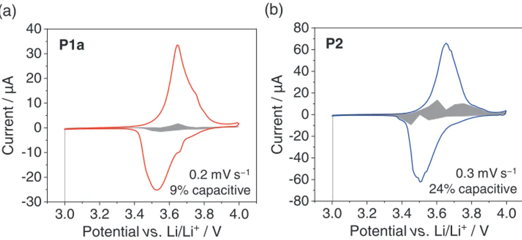
Evalu-ating the peak current for oxidation and reduction (plotting log(i) vs log(ν)) resulted in b-values of 0.55 for P1a and 0.51 for
P2, demonstrating the faradaic nature of the redox processes
(Figure S48, Supporting Information).
With the calculated k-values in hand, the capacitive contri-bution to the total current at a fixed potential V was evaluated using the equation[59]
i V
( )
=k1ν+k1ν0.5 (2)As can be seen in Figure 6, the capacitive contribution was very low for the redox process of both P1a and P2. In particular in P1a-based cells, 91% of the capacity stemmed from faradaic processes.
Calculations served to rationalize the different cycling behavior of polymers P1a and P2. In benchmark calculations, we chose oligomer model systems O1a and O2 for polymers
P1a and P2, respectively, containing two repeating units of the
respective polymer with symmetric endings (see Figure 7 and Supporting Information for details). Calculations were per-formed at the wB97XD[60]/6-31G(d)[61,62] theory level for
struc-ture optimizations followed by single-point energy calculations at the wB97XD/6-311G(d,p)[63–65] theory level for the density of
states (DOS, obtained using the AOMix package[66,67]) and
spin-density (for further detail see Supporting Information).
The DOS (Figure 7a) shows that for O1a, both bithiophene and phenothiazine moieties contributed to the HOMO composi-tion (DOS between −6 and −8 eV). For O2, on the other hand, the major contribution stemmed from the phenothiazine units, while the fluorene moieties played a negligible role. This indicated a higher conjugation degree for O1a than for O2, which could explain the higher rate capability of P1a compared to P2. The spin densities obtained for the first oxidized state are shown in Figure 7b. Both are mostly localized on the phenothiazine units.
In all three oligomer model structures O1a, O2, and O3, the phenothiazine unit planarized upon oxidation from a “but-terfly” angle of about 149° to close to 180° (see Supporting Information for details). In addition, in O1a, the torsional angle between the phenothiazine groups and the adjacent thiophenyl groups became smaller (54° to 35°). This is in line with the enhanced conjugation in polymer P1a.
2.2. Influence of Side Chains on the Cell Performance of P1
Based on the excellent rate performance and cycling stability of bithiophene-based polymer P1a, we next aimed to increase its
0 10,000 20,000 30,000 0 5 10 15 20 25 30 35 40 Discharge capacity Charge capacity Coulombic efficiency g h A m / yti ca pa c cifi ce p S 1-0 20 40 60 80 100
(a)
P1a 100C rate(b)
Cycle number Co ul om bi c effi ci en cy / % 0 5 10 15 20 25 30 35 0 5 10 15 20 25 30 35 3.2 3.4 3.6 3.8 Cycle number 1st 2000th 10000th 30000thSpecific capacity / mAh g−1
Po te nt ia l vs . Li/L i +/ V charge discharge P1a 100C rate
Figure 5. Constant current cycling measurement at 100C rate for P1a (a) with selected charge/discharge curves (b).
3.0 3.2 3.4 3.6 3.8 4.0 -30 -20 -10 0 10 20 30 40
Aµ
/ t
ne
rr
u
C
Potential vs. Li/Li
+/ V
3.0 3.2 3.4 3.6 3.8 4.0 -80 -60 -40 -20 0 20 40 60 80Aµ
/ t
ne
rr
u
C
Potential vs. Li/Li
+/ V
(b)
(a)
0.2 mV s−1 9% capacitive 0.3 mV s−1 24% capacitive P1a P2specific capacity by decreasing the lengths or amount of alkyl side chains and synthesized polymers P1b–d (Scheme 2). In polymer
P1b, all alkyl chains were removed apart from a methyl group
at the nitrogen atom. In P1c and P1d, the aryl ether unit on the nitrogen was maintained, but the branched alkyl chain was replaced with a methyl group. In P1c, the bithiophene groups remained unsubstituted, while in P1d, methyl substituents were
attached. This furthermore allowed us to assess the influence of substituents on the cycling behavior of the polymers, resulting from elec-tronic and conformational differences.
2.2.1. Synthesis of Polymers P1b–d
The syntheses of P1b–d employed pheno-thiazine monomers 7 and 8 together with bithiopene monomers 9 and 10, as shown in Scheme 2. Polycondensations were performed using the optimized Suzuki– Miyaura conditions, as discussed above for
P1a, P2, and P3. The resulting polymers P1b–d were insoluble in common organic
solvents due to the lack of alkyl side chains and precipitated from the reaction mixture. Hence, molecular weights could not be determined. Consecutive Soxhlet extraction with methanol, acetone, ethyl acetate, and dichloromethane allowed obtaining the polymers in sufficient purity for battery cell measurements.
2.2.2. Investigation of Polymers P1b–d as Cathode-Active Battery Materials
To investigate P1b–d as cathode-active materials in batteries, we fabricated composite electrodes as described for P1a, P2, and
P3 above in the ratio of 60 wt% polymer, 35 wt% Super C65
as conductive additive, and 5 wt% PVdF binder. With values of
Figure 7. Computational results for oligomer model systems O1a and O2 (wB97XD/6-311G(d,p)): a) total and partial densities of states (DOS) and b) spin densities for the first oxidized state (isovalue = 0.001).
71.4 mAh g−1 for P1b, 57.3 mAh g−1 for P1c, and 54.1 mAh g−1 for P1d, the theoretical specific capacities are significantly higher than for P1a.
In cyclic voltammograms in composite electrodes, P1b showed a somewhat narrow oxidation peak but a broad re-reduction peak on the cathodic scan and a large peak separa-tion (Figure 8). This likely resulted from the stronger conjuga-tion between the phenothiazine and bithiophene units due to the absence of alkyl chains. Similar electrochemical behavior
has been observed in phenothiazine homopolymers.[31] A
calculation on the radical cation of the corresponding model compound O1b revealed that the spin density was mostly local-ized on a bithiophene unit and only half of the adjacent phe-nothiazine groups (Figure 9b). As a result, the phephe-nothiazine units did not planarize upon oxidation (Figure 9a). This stands in contrast to aryl ether–substituted O1a, O1c, and O1d, where the radical cation was centrally localized on the phenothiazine units, which, as a consequence, planarized upon oxidation (see Figure 9 and Figure S80, Supporting Information). Hence, in polymer P1b, the bithiophene groups significantly partook in the oxidation reaction.[68]
In P1c and P1d, containing an aryl ether substituent on the phenothiazine group, the oxidations were more defined (Figure 8). This had also been the case for P1a (see Figure 2) and is in line with the calculated planarization of the phenothi-azine units upon oxidation in all three model compounds O1a,
O1c, and O1d (see Figure 9). Introducing alkyl substituents
on the bithiophene units led to a further narrowing of the redox peaks in P1d (see also P1a in Figure 2). This localization of charges due to the presence of alkyl substituents in thio-phene copolymers has been demonstrated in other contexts before.[69,70]
In constant current cycling measurements, P1b, featuring the highest theoretical capacity, provided the highest specific capacity at 1C rate, while P1d showed the best rate capability (Figure 10). At 1C rate, all three polymers demonstrated stable cycling behavior. For P1b, a reversible capacity of 56.9 mAh g−1
was accessible, which amounted to 80% of the theoretical value for a one-electron oxidation (the theoretical capacities
can be found in Scheme 2). For P1c, 41.0 mAh g−1 were
acces-sible (72% of the theoretical value), and for P1d, 38.9 mAh g−1
(72% of the theoretical value). The incomplete capacity use in these polymers was likely either due to the presence of polymer agglomerates in the composite electrode caused by their insolu-bility during processing (for SEM images, see Figures S71–S76, Supporting Information) or to the fact that the polymer chains were short and electrochemically inactive end groups reduced the specific capacities. Extending the potential range to 4.1 V
versus Li/Li+ in the upper region allowed accessing higher
capacities for all three polymers P1b–d with stable cycling at 1C rate for P1b and P1c (see Figure S54b–d, Supporting Information).
The charge/discharge curves (Figure 10d–f) demonstrated a behavior similar to the CVs shown in Figure 8; for P1b and P1c,
3.0 3.2 3.4 3.6 3.8 4.0 -0.08 -0.04 0.00 0.04 0.08 0.12 A m / tn err u C Potential vs. Li/Li+ / V 0.05 mV s-1 0.1 mV s-1 0.2 mV s-1 0.3 mV s-1 0.4 mV s-1 0.5 mV s-1 3.0 3.2 3.4 3.6 3.8 4.0 -0.20 -0.15 -0.10 -0.05 0.00 0.05 0.10 0.15 0.20 0.25 A m / tn err u C Potential vs. Li/Li+ / V 0.05 mV s-1 0.1 mV s-1 0.2 mV s-1 0.3 mV s-1 0.4 mV s-1 0.5 mV s-1 3.0 3.2 3.4 3.6 3.8 4.0 -0.08 -0.04 0.00 0.04 0.08 A m / tn err u C Potential vs. Li/Li+ / V 0.05 mV s-1 0.1 mV s-1 0.2 mV s-1 0.3 mV s-1 0.4 mV s-1 0.5 mV s-1 P1c P1d P1b
Figure 8. Cyclic voltammograms of P1b–d in composite electrodes at different scan rates (polymer/carbon black/PVdF (60:35:5 wt%), 1 m LiPF6 in EC/
sloping potential curves were obtained, while P1d showed more defined plateaus. This again can be explained by the presence of the methyl groups on the bithiophene units in P1d, which had a pronounced influence on the localization of charges on the phenothiazine units.
P1d featured the best rate performance followed by P1c and P1b (Figure 10). For P1d, a capacity of 31.5 mAh g−1 was
acces-sible at 100C rate (Figure 10c). The rate capability of P1c was also good, which again can be traced back to the presence of the aryl ether groups on the phenothiazine units. The poorer rate performance of P1b, on the other hand, might be due to 1) the missing planarization of the phenothiazine groups upon oxidation and 2) the larger torsional angle between the thiophene units in the oxidized form compared to P1c and P1d (see Figure 9).
In summary, in spite of the larger amount of inactive mass in P1a compared to P1b–d, this polymer showed the best per-formance regarding accessible capacity, rate capability, and cycling stability. This was due to the electronic effects of the aryl ether group, the steric influence of the bithiophene alkyl groups on the polymer conformation, as well as its high sol-ubility, which allowed for good processing of the composite electrodes. The long alkyl groups in P1a likely favor forma-tion of an amorphous phase in the composite electrode, which accelerates counter ion diffusion, a phenomenon, which has been observed in other redox-active polymers before.[71]
3. Conclusions
In conclusion, we have shown that using a π-conjugated copol-ymer structure enabled ultra-high rate capability and cycling stability at 100C rate in phenothiazine-based polymers as cathode-active battery materials. Best results were achieved with
P1a, possessing alternating phenothiazine and bithiophene
units. We ascribe this to the semiconducting nature of P1a, which allowed for fast charge transport in the composite elec-trode. Yet, due to the copolymer structure, localized phenothia-zine redox centers were maintained along the polymer chain, which resulted in well-defined plateau potentials on charge and discharge at 3.6 V versus Li/Li+, close to the operating poten-tial of commercial Li-ion battery cathodes. The redox processes were mostly faradaic in nature (>90%). Calculations showed that a slightly higher degree of conjugation in P1a compared to fluorene-based copolymer P2 was likely responsible for its superior rate performance. A comparison with polymers P1c–d carrying fewer and smaller substituents demonstrated that both the aryl ether as well as the alkyl substituents in P1a were nec-essary to obtain this outstanding behavior. We believe that this concept of using a π-conjugated copolymer structure is attrac-tive for applications, where a high rate performance of the elec-trode is required.
4. Experimental Section
Synthetic Procedures: Further details on materials and methods as well as synthetic procedures for compounds 1–10 and computational details can be found in Supporting Information.
Microwave reactions were conducted in a Discover S-class microwave oven from CEm. NMR spectra were recorded at room temperature on a Bruker Avance III HD 500, Bruker Avance Neo 400, Bruker Avance II 400, or Bruker Avance III HD 300 spectrometer. Chemical shifts were reported in parts per million (ppm, δ scale). The 1H and 13C spectra
were calibrated against the residual proton and natural abundance 13C
resonances of CDCl3 (1H: 7.26 ppm, 13C: 77.16 ppm) or against TMS
(1H, 13C: 0 ppm). The following abbreviations were used: s = singlet,
d = doublet, t = triplet, m = multiplet, and br = broad. The coupling constants (J) were indicated in Hertz (Hz). Analytical gel permeation chromatography was performed on a SECcurity GPC System from PSS Polymer Standard Service using components of the 1260 Infinity series from Agilent Technologies (IsoPump: G1310B, auto sampler: ALS G1329B, UV-detector: MWD VL G1365D, RI-detector: RID G1362A). Three columns were used (PSS SDV, 8 mm × 300 mm with a porosity of 102, 103, and 105 with integrated pre-column). As eluent, degassed
THF was used with a flow rate of 1 mL min−1. A polystyrene standard
by PSS was used for calibration. For TGA, a STA 409 or a STA 449 F5 by Netzsch and for DSC a Netzsch DSC 204 F1 Phoenix were used. UV–vis absorption and emission spectra were recorded on a Tidas I or Tidas II diode array spectrometer from J&m Analytik AG, and on a Perkin Elmer LS55 in a 10 mm fused quartz cuvette. Cyclic voltammetry in solution was performed inside of a glovebox using a Metrohm Autolab PGSTAT 128N. As working electrode, a glassy carbon disc electrode (2 mm diameters) was used. A platinum rod served as counter electrode, and as reference electrode, a Ag/AgNO3 electrode containing a silver wire
immersed in an inner chamber filled with 0.1 m AgNO3 containing 0.1 m
n-Bu4NPF6 in the outer chamber was used. For the internal reference,
the ferrocene/ferrocenium (Fc/Fc+) redox couple was used.
General Method for the Suzuki Polycondensation (Microwave Assisted): The following optimized method was used for polymers P1a, P2, P3, and P1b (the amounts of reagents and solvents are detailed for each polymer below). Phenothiazine diboronic ester 1 or 7, the respective Figure 9. a) Selected calculated torsional angles (wB97XD/6-31G(d)) for
oligomer model systems O1a–d in the neutral and radical cation state. b) Calculated spin densities (wB97XD/6-311G(d,p)) for the first oxidized state of O1b and O1c (isovalue = 0.001).
dibromo-compound 4, 5, 6, or 9, Aliquat 336, NaOH, Pd2dba3, and
SPhos were dissolved in degassed toluene. Argon-saturated H2O was
added. The vessel was placed in the microwave reactor with the following settings: SPS-mode, 60 W, 90 °C, 30–90 min (depending on solvent volume) with air cooling on. After completion of the reaction time, 4,4,5,5-tetramethyl-2-phenyl-1,3,2-dioxaborolane was added and left to react for 4 min and bromobenzene was added, and the reaction was stirred for another 4 min (same microwave conditions as before). Then the mixture was precipitated from cold acetone. The filtered polymer was redissolved and precipitated from methanol and dried in vacuum.
Synthesis of P1a: The general procedure for the Suzuki polycondensation (microwave assisted) was followed using phenothiazine monomer 1 (0.53 g, 0.81 mmol), bithiophene monomer 4 (0.40 g, 0.81 mmol), Pd2dba3 (29.2 mg, 32.0 µmol, 4 mol%),
SPhos (25.3 mg, 62.0 µmol, 7.7 mol%), NaOH (0.35 g, 8.80 mmol, 11.0 eq.), toluene (6 mL), H2O (2 mL), and Aliquat 336 (2–3 drops).
Polymer P1a (0.59 g, 99%) was obtained as a yellow solid. 1H NMR
(400 MHz, CDCl3): δ 7.34–7.31 (m, 2H), 7.15–7.13 (m, 2H), 7.07 (d, J = 2.1 Hz, 2H), 6.96 (s, 2H), 6.89 (dd, J = 8.8, 2.0 Hz, 2H), 6.21 (d, J = 8.6 Hz, 2H), 3.94–3.93 (m, 2H), 2.58–2.54 (m, 4H), 1.84–1.74 (m, 1H), 1.60–1.43 (m, 8H), 1.39–1.35 (m, 4H), 1.33–1.22 (m, 12H), 1.00–0.96 (m, 3H), 0.95–0.92 (m, 3H), 0.89–0.86 (m, 6H); 13C NMR (101 MHz, CDCl 3): δ 159.4, 143.6, 139.3, 135.6, 135.1, 132.7, 132.1, 128.8, 127.8, 127.1, 125.9, 119.5, 116.7, 115.7, 71.0, 39.6, 31.8, 31.0, 30.7, 29.3, 29.3, 29.0, 24.1, 23.2, 22.8, 14.3 (2C), 11.3; anal. GPC (eluent THF, polystyrene standard): Mn = 3.29 · 104 g mol−1, PDI 2.65;
TGAonset (10 °C min−1, O2): 405 °C.
Synthesis of P2: The general procedure for the Suzuki polycondensation (microwave-assisted) was followed using phenothiazine monomer 1 (68.6 mg, 0.11 mmol), fluorene monomer 5 (51.5 mg, 0.11 mmol), Pd2dba3 (3.80 mg, 4.2 µmol, 4 mol%), SPhos (3.40 mg, 8.40 µmol,
8 mol%), NaOH (46.0 mg, 1.15 mmol, 11.0 eq.), toluene (3 mL), H2O
(1 mL), and Aliquat 336 (2–3 drops). Polymer P2 (49.8 mg, 65%) was obtained as a green solid. 1H NMR (400 MHz, CDCl
3): δ 7.70–7.68 (m, 2H), 7.47–7.44 (m, 4H), 7.37–7.32 (m, 4H), 7.17–7.14 (m, 4H), 6.31–6.29 (m, 2H), 3.97–3.92 (m, 2H), 2.04–1.97 (m, 4H), 1.85–1.77 (m, 1H), 1.64–1.45 (m, 4H), 1.43–1.37 (m, 4H), 1.16–0.94 (m, 18H), 0.78–0.75 (m, 6H), 0.71–0.62 (m, 4H); 13C NMR (101 MHz, CDCl 3): δ 159.4, 151.8, 143.7, 140.0, 138.8, 136.0, 133.2, 132.2, 125.7, 125.3, 125.1, 120.8, 120.0, 119.8, 116.8, 116.1, 71.1, 55.4, 40.6, 39.7, 31.6, 30.8, 29.9, 29.3, 24.1, 24.0, 23.2, 22.7, 14.3, 14.1, 11.4; anal. GPC (eluent THF, polystyrene standard): Mn = 9.40 · 104 g mol−1, PDI 2.00; TGAonset (10 °C min−1, O2): 402 °C.
Synthesis of P3: The general procedure for the Suzuki polycondensation (microwave-assisted) was followed using phenothiazine monomer 1 (70.6 mg, 0.11 mmol), thiophene monomer 6 (56.0 mg, 0.11 mmol), Pd2dba3 (3.90 mg, 4.26 µmol, 3.9 mol%), SPhos (3.60 mg, 8.77 µmol,
8 mol%), NaOH (42.0 mg, 1.05 mmol, 13.6 eq.), toluene (1.5 mL), H2O
(0.5 mL), and Aliquat 336 (2–3 drops). Polymer P3 (53.8 mg, 99%) was obtained as a yellow solid. 1H NMR (400 MHz, CDCl
3): δ 7.28–7.26 (m, 2H), 7.16 (d, J = 2.2 Hz, 2H), 7.12–7.10 (m, 2H), 6.97 (dd, J = 8.6, 2.2 Hz, 2H), 6.86 (s, 2H), 6.12 (d, J = 8.6 Hz, 2H), 3.93–3.92 (m, 2H), 3.00 (s, 4H), 2.44–2.41 (m, 4H), 1.83–1.74 (m, 1H), 1.62–1.42 (m, 8H), 1.40–1.34 (m, 4H), 1.32–1.21 (m, 12H), 0.99–0.96 (m, 3H), 0.95–0.92 (m, 3H), 0.88–0.85 (m, 6H); 13C NMR (101 MHz, CDCl 3): δ 159.3, 143.2, 139.8, 139.2, 136.0, 132.9, 132.1, 129.2, 124.1, 123.9, 123.4, 119.6, 116.6, 115.8, 71.0, 39.6, 31.9, 31.0, 30.7, 30.6, 29.5, 29.3, 28.6, 24.1, 23.2, 22.8, 14.3 (2C), 11.3; anal. GPC (eluent THF, polystyrene standard): Mn = 1.89 · 104 g mol−1, PDI 2.47; TGAonset (10 °C min−1, O2): 402 °C.
Synthesis of P1b: The general procedure for the Suzuki polycondensation (microwave-assisted) was followed using phenothiazine monomer 7 (0.20 g, 0.43 mmol), thiophene monomer 9 (0.14 g, 0.43 mmol), Pd2dba3 (0.02 g, 0.02 mmol, 4 mol%), SPhos
(0.01 g, 0.03 mmol, 8 mol%), NaOH (0.19 g, 4.73 mmol, 11.0 eq.), toluene (4 mL), H2O (1 mL), and Aliquat 336 (2–3 drops). For further
purification the polymer was Soxhlet-extracted with MeOH, acetone, EtOAc, and CH2Cl2. Polymer P1b (0.12 g, 74%) was obtained as a red
solid. TGAonset (10 °C min−1, O2): 410 °C.
Synthesis of P1c: The general procedure for the Suzuki polycondensation (instead of microwave heating an oil bath was used (20 h, 90 °C)) was followed using phenothiazine monomer 8 (1.00 g, 1.79 mmol), thiophene monomer 9 (0.58 g, 1.79 mmol), Pd2dba3
(0.07 g, 0.07 mmol, 4 mol%), SPhos (0.06 g, 0.14 mmol, 8 mol%), Figure 10. Cycling performance of P1b–d-based composite electrodes: a–c) C-rate tests; d–f) selected charge/discharge curves of constant current cycling measurements at 1C rate (polymer/carbon black/PVdF (60:35:5 wt%), 1 m LiPF6 in EC/DMC (1:1), counter/reference electrode: Li foil).
NaOH (0.79 g, 19.7 mmol, 11 eq.), toluene (20 mL), H2O (5 mL), and
Aliquat 336 (5 drops). For further purification the polymer was Soxhlet-extracted with MeOH, acetone, EtOAc, and CH2Cl2. Polymer P1c (0.75 g,
89%) was obtained as a red solid. TGAonset (10 °C min−1, O2): 337 °C.
Synthesis of P1d: The general procedure for the Suzuki polycondensation (instead of microwave heating an oil bath was used (20 h, 90 °C)) was followed using phenothiazine monomer 8 (1.00 g, 1.79 mmol), thiophene monomer 10 (0.63 g, 1.79 mmol), Pd2dba3
(0.07 g, 0.07 mmol, 4 mol%), SPhos (0.06 g, 0.14 mmol, 8 mol%), NaOH (0.79 g, 19.7 mmol, 11 eq.), toluene (20 mL), H2O (5 mL), and
Aliquat 336 (5 drops). For further purification the polymer was Soxhlet-extracted with MeOH, acetone, EtOAc, and CH2Cl2. Polymer P1d (0.79 g,
89%) was obtained as a green solid. TGAonset (10 °C min−1, O2): 378 °C.
Fabrication of Composite Electrodes: Composite electrodes were prepared using 60 wt% polymer, 35 wt% carbon black (Super C65, Timical), and 5 wt% binder (PVdF, Solef 5130) immersed in 1-methyl-2-pyrrolidone (NMP, 99.5%, ACROS Organics, stored over molecular sieves). The mixtures were stirred for 12 h at room temperature. Because of inhomogeneous particle sizes, the mixture for P1d was additionally homogenized using a ball mill (Pulverisette 7 from Fritsch). The resulting paste was blade-coated onto KOH-etched aluminum foil (1235 aluminum foil, H18 hard state, 20 µm from Gelon LIB), resulting in a wet-film thickness of 100 µm. The coated aluminum foil was dried at 80 °C in a vacuum oven at 10−2 mbar, and electrodes with a diameter
of 12 mm were punched out with an electrode-punching device (coin cell punching machine GN-T06 from Gelon LIB). The dried electrodes showed film thicknesses for P1a of 10–18 µm, for P2 of 16–26 µm, for P3 of 23–26 µm, for P1b of 10–20 µm, for P1c of 26–35 µm, and for P1d of 20–30 µm (measured with a Mitutoyo MT547-400S thickness gage), and the mass loadings lay between 0.10 mg and 1.10 mg per electrode (1.13 cm2).
Electrochemical Characterization and Analysis: Three-electrode Swagelok T-cells were assembled in an Ar-filled glovebox (UNILAB 230V from MBraun) containing less than 0.1 ppm of water and oxygen. Lithium (Alfa Aesar, 99.9%) foil was used as counter (Ø = 12 mm) and reference electrode (Ø = 5 mm). Six layers of Freudenberg 2190 nonwoven PP separators were placed between the electrodes (1 m
LiPF6 in EC/DMC: 1/1, BASF Selectilyte, 120 µL). Cyclic voltammetry
and galvanostatic cycling measurements on these cells were conducted on a MPG-2 potentiostat from BioLogic Science Instruments.
Supporting Information
Supporting Information is available from the Wiley Online Library or from the author.
Acknowledgements
P.A. thanks J. Haxhija and F. Hilfinger for preparative assistance, S. Küspert und A. Becherer for SEM measurements, and Prof. B. Breit for use of the microwave synthesizer. Financial support through the German Federal Environmental Foundation (DBU, graduate fellowship for P.A.), the German Research Foundation (DFG, Emmy Noether grant ES 361/2-1 for B.E.), the Swedish Energy Agency (C.M.A. and C.F.N.M., grant number 45420–1), STandUP for Energy, and Carl Tryggers Stiftelse is gratefully acknowledged. The theoretical calculations were done using the infrastructure provided by the Swedish National Infrastructure for Computing (SNIC) at the National Supercomputer Centre at Linköping University (NSC).
Conflict of Interest
The authors declare no conflict of interest.
Keywords
conjugated polymers, microwave chemistry, organic batteries, phenothiazine, redox chemistry
Received: August 6, 2019 Published online: September 1, 2019
[1] H. Nishide, K. Oyaizu, Science 2008, 319, 737.
[2] H. Nishide, K. Koshika, K. Oyaizu, Pure Appl. Chem. 2009, 81, 1961. [3] Y. Liang, Z. Tao, J. Chen, Adv. Energy Mater. 2012, 2, 742.
[4] T. Janoschka, M. D. Hager, U. S. Schubert, Adv. Mater. 2012, 24, 6397.
[5] Z. Song, H. Zhou, Energy Environ. Sci. 2013, 6, 2280. [6] Z. Zhu, J. Chen, J. Electrochem. Soc. 2015, 162, A2393.
[7] Y. Zhang, J. Wang, S. N. Riduan, J. Mater. Chem. A 2016, 4, 14902. [8] J. Xie, Q. Zhang, J. Mater. Chem. A 2016, 4, 7091.
[9] T. B. Schon, B. T. McAllister, P.-F. Li, D. S. Seferos, Chem. Soc. Rev. 2016, 45, 6345.
[10] Q. Zhao, Y. Lu, J. Chen, Adv. Energy Mater. 2017, 7, 1601792. [11] S. Lee, G. Kwon, K. Ku, K. Yoon, S.-K. Jung, H.-D. Lim, K. Kang,
Adv. Mater. 2018, 1704682. [12] Y. Liang, Y. Yao, Joule 2018, 2, 1690.
[13] M. Armand, J.-M. Tarascon, Nature 2008, 451, 652. [14] P. Poizot, F. Dolhem, Energy Environ. Sci. 2011, 4, 2003.
[15] P. Novák, K. Müller, K. S. V. Santhanam, O. Haas, Chem. Rev. 1997, 97, 207.
[16] J. F. Mike, J. L. Lutkenhaus, ACS Macro Lett. 2013, 2, 839. [17] R. Gracia, D. Mecerreyes, Polym. Chem. 2013, 4, 2206.
[18] S. Muench, A. Wild, C. Friebe, B. Häupler, T. Janoschka, U. S. Schubert, Chem. Rev. 2016, 116, 9438.
[19] M. E. Speer, M. Kolek, J. J. Jassoy, J. Heine, M. Winter, P. M. Bieker, B. Esser, Chem. Commun. 2015, 51, 15261.
[20] E. P. Tomlinson, M. E. Hay, B. W. Boudouris, Macromolecules 2014, 47, 6145.
[21] K. Oyaizu, H. Nishide, Adv. Mater. 2009, 21, 2339.
[22] K. Nakahara, K. Oyaizu, H. Nishide, Chem. Lett. 2011, 40, 222. [23] H. E. Katz, P. C. Searson, T. O. Poehler, J. Mater. Res. 2010, 25,
1561.
[24] J. Xie, P. Gu, Q. Zhang, ACS Energy Lett. 2017, 2, 1985.
[25] V. Etacheri, R. Marom, R. Elazari, G. Salitra, D. Aurbach, Energy Environ. Sci. 2011, 4, 3243.
[26] Y. Liang, Z. Chen, Y. Jing, Y. Rong, A. Facchetti, Y. Yao, J. Am. Chem. Soc. 2015, 137, 4956.
[27] K. T. Sarang, A. Miranda, H. An, E.-S. Oh, R. Verduzco, J. L. Lutkenhaus, ACS Appl. Polym. Mater. 2019, 1, 1155.
[28] M. Kolek, F. Otteny, P. Schmidt, C. Mück-Lichtenfeld, C. Einholz, J. Becking, E. Schleicher, M. Winter, P. Bieker, B. Esser, Energy Environ. Sci. 2017, 10, 2334.
[29] F. Otteny, M. Kolek, J. Becking, M. Winter, P. Bieker, B. Esser, Adv. Energy Mater. 2018, 1802151.
[30] A. A. Golriz, T. Suga, H. Nishide, R. Berger, J. S. Gutmann, RSC Adv. 2015, 5, 22947.
[31] T. Godet-Bar, J.-C. Leprêtre, O. Le Bacq, J.-Y. Sanchez, A. Deronzier, A. Pasturel, Phys. Chem. Chem. Phys. 2015, 17, 25283.
[32] B. M. Peterson, D. Ren, L. Shen, Y.-C. M. Wu, B. Ulgut, G. W. Coates, H. D. Abruña, B. P. Fors, ACS Appl. Energy Mater. 2018, 1, 3560. [33] T. Shimizu, K. Yamamoto, P. Pandit, H. Yoshikawa,
S. Higashibayashi, Sci. Rep. 2018, 8, 579.
[34] M. Kolek, F. Otteny, J. Becking, M. Winter, B. Esser, P. Bieker, Chem. Mater. 2018, 30, 6307.
[35] K. A. Narayana, M. D. Casselman, C. F. Elliott, S. Ergun, S. R. Parkin, C. Risko, S. A. Odom, ChemPhysChem 2015, 16, 1179.
[36] D.-H. Hwang, S.-K. Kim, M.-J. Park, J.-H. Lee, B.-W. Koo, I.-N. Kang, S.-H. Kim, T. Zyung, Chem. Mater. 2004, 16, 1298.
[37] X. Kong, A. P. Kulkarni, S. A. Jenekhe, Macromolecules 2003, 36, 8992.
[38] M. Łapkowski, S. Plewa, A. Stolarczyk, J. Doskocz, J. Sołoducho, J. Cabaj, M. Bartoszek, W. W. Sułkowski, Electrochim. Acta 2008, 53, 2545.
[39] S. Yamada, S. Park, S. Song, M. Heo, J. Y. Shim, Y. Jin, I. Kim, H. Lee, K. Lee, K. Yoshinaga, J. Y. Kim, H. Suh, Polymer 2010, 51, 6174.
[40] W. Tang, T. Kietzke, P. Vemulamada, Z.-K. Chen, J. Polym. Sci. Part A Polym. Chem. 2007, 45, 5266.
[41] H. S. Yoo, D. H. Yun, T. W. Ko, Y. S. Park, J. W. Woo, Adv. Mater. Res. 2013, 634–638, 2621.
[42] M. Takahashi, K. Masui, H. Sekiguchi, N. Kobayashi, A. Mori, M. Funahashi, N. Tamaoki, J. Am. Chem. Soc. 2006, 128, 10930.
[43] R. Bernard, C. Barsu, P. L. Baldeck, C. Andraud, D. Cornu, J.-P. Scharff, P. Miele, Chem. Commun. 2008, 3765.
[44] B. W. D’Andrade, S. Datta, S. R. Forrest, P. Djurovich, E. Polikarpov, M. E. Thompson, Org. Electron. 2005, 6, 11.
[45] C. O. Laoire, E. Plichta, M. Hendrickson, S. Mukerjee, K. M. Abraham, Electrochim. Acta 2009, 54, 6560.
[46] T. J. J. Müller, A. W. Franz, C. S. Barkschat (née Krämer), M. Sailer, K. Meerholz, D. Müller, A. Colsmann, U. Lemmer, Macromol. Symp. 2010, 287, 1.
[47] M. Sailer, A. W. Franz, T. J. J. Müller, Chem. Eur. J. 2008, 14, 2602. [48] All Capacities Herein Are Reported per Mass of Active Material. [49] K. Nakahara, J. Iriyama, S. Iwasa, M. Suguro, M. Satoh, E. J. Cairns,
J. Power Sources 2007, 165, 398.
[50] P. Meister, H. Jia, J. Li, R. Kloepsch, M. Winter, T. Placke, Chem. Mater. 2016, 28, 7203.
[51] S. F. Tie, C. W. Tan, Renew. Sustain. Energy Rev. 2013, 20, 82. [52] S. Komaba, T. Tanaka, T. Ozeki, T. Taki, H. Watanabe, H. Tachikawa,
J. Power Sources 2010, 195, 6212.
[53] J.-K. Kim, J.-H. Ahn, G. Cheruvally, G. S. Chauhan, J.-W. Choi, D.-S. Kim, H.-J. Ahn, S. H. Lee, C. E. Song, Met. Mater. Int. 2009, 15, 77.
[54] K. Yamamoto, D. Suemasa, K. Masuda, K. Aita, T. Endo, ACS Appl. Mater. Interfaces 2018, 10, 6346.
[55] C. Zhang, X. Yang, W. Ren, Y. Wang, F. Su, J.-X. Jiang, J. Power Sources 2016, 317, 49.
[56] J. K. Feng, Y. L. Cao, X. P. Ai, H. X. Yang, J. Power Sources 2008, 177, 199.
[57] Y. Gogotsi, R. M. Penner, ACS Nano 2018, 12, 2081.
[58] H. Lindström, S. Södergren, A. Solbrand, H. Rensmo, J. Hjelm, A. Hagfeldt, S.-E. Lindquist, J. Phys. Chem. B 1997, 101, 7717. [59] V. Augustyn, E. R. White, J. Ko, G. Grüner, B. C. Regan, B. Dunn,
Mater. Horiz. 2014, 1, 219.
[60] J.-D. Chai, M. Head-Gordon, J. Chem. Phys. 2008, 128, 084106. [61] W. J. Hehre, R. Ditchfield, J. A. Pople, J. Chem. Phys. 1972, 56, 2257. [62] M. M. Francl, W. J. Pietro, W. J. Hehre, J. S. Binkley, M. S. Gordon,
D. J. DeFrees, J. A. Pople, J. Chem. Phys. 1982, 77, 3654. [63] A. D. McLean, G. S. Chandler, J. Chem. Phys. 1980, 72, 5639. [64] R. Krishnan, J. S. Binkley, R. Seeger, J. A. Pople, J. Chem. Phys. 1980,
72, 650.
[65] M. J. Frisch, J. A. Pople, J. S. Binkley, J. Chem. Phys. 1984, 80, 3265. [66] S. I. Gorelsky, AOMix: Program for Molecular Orbital Analysis 2012,
http://www.sg-chem.net/.
[67] S. I. Gorelsky, A. B. P. Lever, J. Organomet. Chem. 2001, 635, 187. [68] T. Tao, H.-F. Qian, K. Zhang, J. Geng, W. Huang, Tetrahedron 2013,
69, 7290.
[69] F. Lombeck, D. Di, L. Yang, L. Meraldi, S. Athanasopoulos, D. Credgington, M. Sommer, R. H. Friend, Macromolecules 2016, 49, 9382.
[70] R. Steyrleuthner, Y. Zhang, L. Zhang, F. Kraffert, B. P. Cherniawski, R. Bittl, A. L. Briseno, J.-L. Bredas, J. Behrends, Phys. Chem. Chem. Phys. 2017, 19, 3627.
[71] Z. Niu, H. Wu, L. Liu, G. Dai, S. Xiong, Y. Zhao, X. Zhang, J. Mater. Chem. A 2019, 7, 10581.