WEDA POOL CLEANER CONCEPT P100
HARED ABUKAR
FIRAS AL SAATI
Master of Science Thesis Stockholm, Sweden 2016
Weda Pool Cleaner Concept P100
Hared Abukar
Firas Al Saati
Master of Science Thesis MMK 2016:175 MKN 180 KTH Industrial Engineering and Management
Machine design SE-100 44 STOCKHOLM
Examensarbete MMK 2016:175 MKN 180
Weda pool cleaner Concept P100
Hared Abukar Firas Al Saati Godkänt 2016-11-29 Examinator Claes Tisell Handledare Conrad Luttropp Uppdragsgivare Weda AB Kontaktperson Klas Lange
Sammanfattning
Syftet med detta examensarbete var att ta fram en ny drivlina för Wedas nuvarande robot poolrengörare W50. I nuläget är pumpen integrerad i drivlinan som består endast av en motor som driver både hjul och pump. Detta orsakar ett kritiskt problem som påverkar städning vid lutningar i poolen då roboten glider ner för lutningen.
För att få en bättre insikt i hur produkten fungerar gjordes studiebesök till Weda. Projektgruppen dokumenterade och observerade hur den nuvarande modellen och dess komponenter är monterade. Intervjuer utfördes med vaktmästare och fastighetsskötare inom olika kommunala bad och hotellpooler för att få en djupare förståelse för hur dessa robot poolrengörare används och vilka förbättringsområden som finns. Faktainsamlingen användes som grund för att ta fram förslag för nya och alternativa komponenter till det nya konceptet. De olika lösningarna blev sedan utvärderade med hjälp en beslutsmatris för att kunna bestämma vilka komponenter som skulle ingå i det slutgiltiga konceptet.
Arbetet har utförts i nära samarbete med Adigo Drives, som bistått med sin expertis gällande motorer och drivlinor.
Resultatet utmynnade i ett slutgiltigt koncept med en ny drivlina och en lägre vikt än den befintliga roboten.
Master of Science Thesis MMK 2016:175 MKN 180
Weda pool cleaner Concept P100
Hared Abukar Firas Al Saati Approved 2016-11-29 Examiner Claes Tisell Supervisor Conrad Luttropp Commissioner Weda AB Contact person Klas Lange
Abstract
The purpose of this study was to develop a new drivetrain for Wedas current robot pool cleaner W50. Currently, the pump is integrated in the drivetrain which contains only one motor running both wheels and pump. This causes a critical problem affecting cleaning when encountering inclinations in the pool, the robot slides down the slope.
To get a better understanding of how the product works, the project group made study visits to Weda. The group documented and observed how the current model and its components are mounted. Interviews were conducted with caretakers and janitors at various municipal swimming pools and hotel pools to get a deeper understanding of how these robot pool cleaners are used and what areas for improvement that exists. The research was used as a foundation for suggestions of new and alternative components for the new concept. The different solutions were then evaluated using a decision matrix to determine which components should be included in the final concept.
The work has been carried out in close cooperation with Adigo Drives, which assisted the group with their expertise regarding motors and powertrains.
The results culminated in a final concept with a new powertrain and a lower weight than the existing robot.
PREFACE
The project presented in this Master thesis was assigned by Weda AB and was conducted within the masters programme of Industrial Design engineering at KTH, The Royal Institute of Technology.
We would like to thank Adigo Drives AB for their assistance and expertise with electronic systems during this project. We would also like to thank the staff and engineers of Weda AB for providing us with knowledge within the field of pool cleaning. But also for making us feel welcome and appreciated at the company.
Thanks to all the participants that gave us valuable insights for the development of the new concept. And finally, Conrad Luttropp, our supervisor at KTH for his guidance and encouragement to achieve our goals.
Hared Abukar and Firas Al Saati November 2016
TABLE OF CONTENT
1 INTRODUCTION ... 1 2 POOL CLEANING ... 3 3 THE CURRENT ROBOT W50 ... 5 3.1 WEDA W50 ... 5 3.2 CURRENT CONFIGURATION ... 6 3.3 REQUIREMENT SPECIFICATION ... 9 3.4 COMPETITOR ANALYSIS ... 10 3.5 QUALITATIVE RESEARCH ... 11 3.6 USER ANALYSIS ... 12 3.7 SWOT ... 14 3.8 FUNCTIONAL ANALYSIS ... 15 3.9 MARKET CHART ... 16 4 SUGGESTIONS FOR NEW COMPONENTS ... 17 4.1 PUMP AND IMPELLER ... 17 4.2 DRIVETRAIN ... 19 5 CONCEPT DEVELOPMENT AND SELECTION ... 21 5.1 COMBINATIONS ... 21 5.2 PUGH’S DECISION MATRIX ... 23 5.3 FINAL COMPONENT SELECTION ... 23 5.4 BRAINSTORMING ... 24 5.5 VISUALSTORMING ... 24 5.6 DESIGN SELECTION ... 25 5.7 COMPUTER AIDED DESIGN - CAD ... 25 6 THE NEW ROBOT P100 ... 27 6.1 DESIGN AND FUNCTION ... 27 6.2 SENSORS AND INLET ... 286.3 PUMP, IMPELLER AND FILTER ... 29 6.4 DRIVETRAIN AND SETUP ... 30 7 DISCUSSION AND CONCLUSION ... 33 7.1 DISCUSSION ... 33 7.2 CONCLUSION ... 34 8 FURTHER WORK ... 35 8.1 RECOMMENDATIONS ... 35 8.2 FUTURE DEVELOPMENT ... 35 9 REFERENCES ... 37 10 TABLE OF FIGURES ... 40 APPENDIX ... 42
1 INTRODUCTION
Background
Weda is a Swedish company located in Stockholm that specializes in underwater cleaning solutions with automatic and semi-automatic robots. The robots are built for different purposes and are used within different industries such as; the pool industry, water and sewage industry. The robot cleaners are based on more than 50 years of experience within pumps for underwater usage. Weda markets the cleaners’ worldwide with the major platform being the European Union and especially Germany where there are 8000 public pools and Weda has its own subsidiary. Other important markets today for the pool cleaners from Weda are the Middle East and North America.
Problem definition
One of the main issues with the current model Weda W50 resides within the drivetrain. Mainly the pump that cannot achieve effective suction when encountering steep slopes which causes it to slide down an inclination. This is due to the pump being connected to the wheels thus performing to two tasks (pumping and driving the wheels) at the same time.
Aim
The main goal was to develop an underwater pool cleaner concept with a new drivetrain. The new concept should be based on the existing model Weda W50 with under the hood changes that allows the robot to continue cleaning when encountering inclinations in a pool.
Other objectives were:
• Evaluate alternate drivetrain solutions
• Deliver a complete concept based on research findings • Supply a CAD model of the solution for future prototyping • Deliver a report and a presentation
The intended target group for this new concept was swimming pools in spa’s, schools, municipal baths and hotels. Those that are responsible for cleaning the pools and using the robot pool cleaner are janitors and/or cleaning companies. Henceforth, they are going to be called users in this thesis.
Methods
To reach the goals in this thesis, various data-gathering, tools for idea generation and decision making methods were used. The product design and development process applied in this thesis is based on (Johannesson, et al., 2004). See APPENDIX 2 for further review of the product development process.
The process for the project was divided into different phases. The project commenced with a background research and data gathering phase which allowed the group to delve deeper into understanding the product and the scope of the concerned areas. Literature studies and study visits were also carried out to gain an understanding about assembly and the different components that are used within a robot pool cleaner. Qualitative data was also gathered from 18 interviews with pool caretakers to gain useful insights about the usage of robot cleaners and where improvements could be made. Furthermore, a SWOT-analysis and a functional analysis were done to analyse the strengths and drawbacks of the company as well as the product. Thereafter, a requirement specification was compiled based on the research done by the project group and requirements demanded by Weda.
The research provided a qualitative foundation for developing a concept and moving further on with the project by starting the concept generation phase. As part of this phase, new components were suggested and evaluated using Pugh’s decision matrix. Subsequently, the project group used brainstorming and visualstorming as a catalyst for new ideas, function and design.
In the last phase of this thesis, the concept development phase, the group continued working on the selected components and design by using CAD (Computer Aided Design). The final concept was dimensioned and optimized to meet the requirement specification.
Limitations
No mechanical calculations or calculations on flows were made, however, mechanical principles were considered when designing the final concept. No physical concept will be built. Another area which was not considered was wall cleaning because it was not required by Weda.
2 POOL CLEANING
This chapter focuses on pool cleaning in general and what methods are available today.
Why are robot cleaners used?
Skimming the surface of a pool to remove floating debris is a common and a fast way to keep the pool clean (Lynn, 2010). However, at some point the dirt will sink and will become harder to clean and for this reason, a robot pool cleaner is the best option as its sole purpose is to clean the pool floor (Weda, 2010). The robot pool cleaner has a self-contained filtration system that uses rotating brushes to scrub the pool floor and a pump to obtain suction for collecting the debris within the filter bag. The system cleans the pool faster than any other type of cleaning options as there are programs that allows it to run automatically in an efficient cleaning pattern along the pool floor (Lynn, 2010).
According to Darko Mucic (Senior engineer at Weda), the main difference between industrial robot cleaners and commercial cleaners for regular consumers is that the professional cleaners are more durable and are designed to run for an extended period of time. The industrial pool cleaner usually requires low maintenance compared to the commercial models.
Pool cleaning options
Keeping the pool clean requires time and attention as the pool gets contaminated with debris. The type of cleaning technology required for the pool to stay clean depends on the shape and the size of the pool. Swimming pools usually have a main pump that circulates the water around the pool and runs the water through a filter before circulating it back. It is not always that you get the desired effect. Therefore, the pool needs a complimentary cleaning option (Swimmingpool, 2016). There are a wide variety of complementary pool cleaning options that can be divided into three categories: manual, semi-automatic and automatic cleaning.
Manual cleaning of the pool can be achieved by using a pool brush to scrub the walls of the pool or by using a pool skimmer to collect the debris on the surface of the pool water, see figure 2. This type of cleaning is time consuming and needs to be thorough to achieve sufficient results. A semi-automatic option can be a pool vacuum that uses a sand filter and a hose in conjunction with a telescopic pole to manoeuvre the hose around the pool (Lynn, 2010), see figure 3. This method provides reasonable cleaning but it's not perfect and still time consuming.
Automatic cleaning involves using a fully automated system such as the Weda W50 to scrub and clean pool floors, some models also scrub the pool walls (Weda, 2010). The automatic robot uses rotating brushes and a self-contained filter to collect the debris. There are programs that allows it to moves in patterns with the help of laser sensors to detect walls and obstacles. This system is fully autonomous and more effective but more expensive compared to the other two cleaning options.
Figure 4. Clubliner, a competitor to the W50
3 THE CURRENT ROBOT W50
This chapter focuses on information gathering as this was crucial to the development of the Weda pool cleaner concept. The chapter also details what kind of components are used in the current robot. Tools such as SWOT and Functional analysis were also used. Furthermore, competitors were analyzed and interviews were done.
3.1 Weda W50
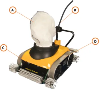
Weda W50 is the current model sold by Weda. It is a professional compact cleaner with rotating brushes that ensures high cleaning capacity. Weda W50 is supplied with a single-phase 230 V AC motor. This motor makes up the whole drivetrain which includes wheels and pump. The drivetrain is the group of components that connects the motor and transmission to the wheel axles (mistertransmission, u.d.). The drivetrain weighs about 17,5 kg and accounts for 62,5 percent of the total weight of the robot (Weda, 2010). The current model is based on an electrical submersible pump with a pump capacity of 600 l/min. Its design has a dual colour scheme like the rest of the company’s products, but the overall design has not been updated in 20 years. Weda W50 is also equipped with either laser sensors or mechanical sensors for detecting corners and walls but also allows for fully automatic cleaning. The total weight on land (outside pool) is approximately 28 kg and when submerged in water, it weighs approximately 12 kg. The dimensions for W50 are (LxWxH): 65 x 50 x 30 cm.
Other standard equipment that is shipped with the W50 is an electrical control box on land, a floating cable (contains all electrical wiring) that is 30 meters long and a radio remote control for manual steering. The life span is approximately 25 years with service and maintenance provided by Weda. The estimated run time for cleaning is 3-5 hours depending on the size of the pool.
Components:
[A] Filter
[B] Floating cable
[C] Mechanical/laser sensors [D] Track band
3.2 Current configuration
Drivetrain and pump
The current Weda W50 drivetrain consists of a single electric motor (same motor as the pump) and a worm gear connected to two separate wheels in the back. The two wheels are both
connected to the front wheels through rubber band tracks that transmits the torque and make the front wheels rotate. The drivetrain and pump consists of the following components, as seen in figure 6:
Components:
[1] Inlet [2] Outlet
[3] Pump chamber [4] Worm gear housing [5] Motor
[6] Rubber strip
Figure 6. Top view (left), bottom view (right)
Since the wheels are in a fixed position, the manoeuvring of the robot is handled by the clutches connected to each wheel in the back. The robot automatically chooses which wheel that will receive the torque. When for example turning left, the clutch detaches in the left wheel and only transmits the torque to the right wheel, thus turning the robot left. However, by using complex parts such as a worm gear and clutches (seen in figure 7), more weight is added to the robot and there is always power loss along the drivetrain which adds to more power consumption (Pratte, 2010).
Figure 7. CAD model displaying the principal setup of the worm gear and clutches in the W50
The current pump is a centrifugal pump which uses an impeller attached to a shaft. The shaft rotates and the impeller transports the fluids through the pump chamber [3:fig6] and out through an outlet [2:fig6]. The liquid is then transported into a filter bag where the debris is collected. This design setup does not protect the impeller from unclean liquids and decreases effective suction rate when the robot turns. (Girdhar & Octo, 2004).
The same shaft is also connected to the drivetrain. The suction decreases when the robot turns in slopes and when encountering an inclination at 30 degrees which causes it to slide down the slope in the pool, as seen in figure 9. The same problem also occurs when the robot tries to drive uphill. This is due to the current design where the pump is connected to the wheels. Even though the pumps capacity is relatively high and delivers 600 l/min, the drivetrains RPM (Rotation Per Minute) is lower to maintain the robots speed of 0,2 m/s which directly affects the suction capacity when encountering inclinations.
Figure 8. Close-up of current drivetrain and impeller
According to D. Mucic (senior engineer at Weda AB), there are other factors that contribute to this problem such as the robot's weight. Another issue is the rubber strip [6:fig6] placed on the bottom of the robot (used for scraping solid debris on the pool floor). The rubber strip limits the flow of water coming into the pump through the inlet [1:fig6]. In order for the pump to generate
the suction needed to remain on the pool floor it needs an open flow of water which the rubber strip design does not currently allow.
Due to it being a centrifugal pump no pressure is being obtained and therefore no vacuum can be created to drive on slopes without sliding.
Figure 9. Visual of where sliding occurs when encountering an inclination in a swimming pool
Impeller
The impeller is one of the vital components in a centrifugal pump, when the impeller rotates it generates the suction needed to transport the liquid (Grundfos, u.d.). The vanes of an impeller, whether they are curved or straight, determine the flow conditions of the centrifugal pump. The W50 uses a semi-closed impeller with straight vanes. This design allows the impeller to deliver the same flow even when rotating counter clockwise, which is needed when the robots is driving in reverse since the same shaft is connected to the drivetrain.
Figure 10. Semi-closed impeller with straight vanes. The impeller design used in W50
Filter
In the current model, the pump process starts with a rotating brush that brushes the pool floor. The pump then creates a suction that causes the removed debris to pass into the suction hole at the bottom of the robot. The debris then enters the impeller chamber and is transported by a vortex through the filter.
The problem with placing the filter after the pump is that it increases the possibility of the debris or foreign objects (such as: glasses, broken tiles and chewing gum) damaging the impeller or incapacitating it. This option is however more cheap in terms of material used and manufacturing (Deltapure, 2016).
Having the filter before the pump chamber, prevents any debris from entering the pump chamber. However, this setup decreases the flow and therefore increases the workload of the pump (Deltapure, 2016).
3.3 Requirement specification
• Motor 24 V AC/30 V DC.
• Two separate motors can be used. Alternatively, a one motor solution such as the current Weda W50 (but with DC motors)
• Pump 24 V AC/30 V DC • Pump capacity 300 l/min
• Should be able to handle inclination of 30 degrees on the pool floor • Weigh less than 28 kg
• Use the same drive wheels and tracks as the existing Weda W50 if no better solution is found
• Minimal use of electronics inside the robot
When all above requirements are met, the group will continue with the final design issues and use as much as possible from the current W50 cleaner.
EU-regulation
All present Weda models are today supplied with electric asynchronous 42 V AC or 230 V AC motors.According to K. Lange (CEO of Weda) there is a possibility within the European Union that new standards will be established limiting the allowed voltage in the pool to 24 V AC or 30 V DC. Several of Weda’s competitors are today offering these low voltage cleaners.
3.4 Competitor analysis
The robot pool cleaning market is dominated by companies such as: Weda, Maytronics, Piraya and Mariner 3S. The pool cleaning robots that have been chosen for this study are all suitable for pools up to 25 m in length and are professional automated heavy-duty cleaners. As opposed to the other competitors, the Weda W50 does not climb and clean walls.
Clubliner by Mariner 3S
Clubliner is an underwater cleaning robot manufactured by the Swiss company Mariner 3S (Mariner 3S, u.d.). It is considered by Weda to be one of their main competitors on the German market.
• The Clubliner offers a low voltage motor at 26 V DC • The pump capacity is 500 l/min
• The weight of the Clubliner is 16 kg
The filter cartridges are placed internally and before the pump which means that unclean liquids run through the filter first and then trough the pump. This design allows the pump to be protected against blockage and damage which extends the pumps life-span (Mariner 3S, u.d.).
Figure 11. Clubliner
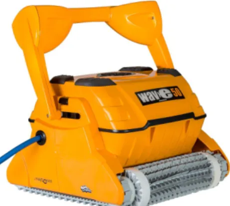
Dolphin Wave 100 by Maytronics
One of the other main competitor robots is the Dolphin Wave 100 produced by the Israeli company Maytronics. The company operates in the USA, Europe, South America and Australia (Maytronics, 2016). Maytronics offers under water robot cleaners in different segments such as; industrial, residential, bio and nature pools (Dolphin by maytronics, 2016).
• The Dolphin Wave 100 operates with dual-drive motors at 24 V DC • Pump capacity of 284 l/min
• The weight of the robot is 11 kg which makes it the lightest weight robot out of the three main competitors (Dolphin by maytronics, 2016)
As for the filter system, the Wave 100 uses an internal filter bag that is placed before the pump. This means that the debris is collected before reaching the pump chamber. The filter system has an indicator that notifies the user when the filter bag is full and needs to be cleaned (HeronPiscine, 2014).
Figure 12. Dolphin Wave 100
Piraya by Piraya Technology AB
A popular choice among Swedish municipal bath facilities is the Piraya robot. It is a low cost alternative to W50. It is developed by a Swedish company Piraya Technology which is also located in Södertälje just as Weda.
• Supplied with a 42 V AC motor • The pump capacity is 800 l/min
• The weight of the Piraya is 15kg (Piraya Technology AB, u.d.)
Figure 13. Piraya
3.5 Qualitative research
Weda
To gain a deeper insight about Weda and its robot pool cleaners, study visits were made to observe the W50 and its internal components. The project group disassembled several components such as the motor and pump to better understand the inner workings and mechanisms of the W50. Video recordings were also made to observe the assembly of the W50. Other robot pool cleaners made by Weda were also inspected and disassembled. These robots had a dual-motor drive with an independent pump unlike the Weda W50. Interviews were mainly conducted with D. Mucic, this helped the group in gaining knowledge about how future solutions of the Weda pool cleaner concept might be designed.
Adigo Drives
Adigo Drives is a Swedish company that designs complex customary solutions for electric motor systems. The company is based in Mölndal outside Gothenburg where all construction, assembly and logistics are made.
The project group contacted Adigo Drives in the early stages of this research to gain help in developing a new drivetrain which included a new motor and gear module. Several Skype-meetings and interviews were held during the entire process and development to better optimize the effectivity, voltage and dimensions of the new motor setup.
SPX Flow
As part of the development for the new drivetrain and pump, the project group contacted SPX Flow Technology Sweden AB. Based in Örebro, SPX Flow is a global multi-industry supplier and manufacturer. SPX Flow contributed with its knowledge about centrifugal pumps and bilge pumps. The outcome of mail conversations and phone-meetings with SPX Flow was a gained understanding about how pumps work and what kind of pumps are applicable for the new Weda pool cleaner concept.
3.6 User analysis
Interviews were conducted to evaluate the existing robot pool cleaners and what complaints that might concern actual users of the robots.
The target groups chosen for this survey were hotels, spa’s and communal baths. The criteria for the interviews was usage of a pool cleaning robot and a pool of at least 12 m in length. Interviews were done with 18 subjects that consisted of facility managers, pool caretakers and cleaning consultants.
The interviews were semi-structured to instigate the interviewee to freely talk about the subject allowing new ideas to be brought up (see APPENDIX 3). The four locations that were visited were:
• Grand Hotel Stockholm - Robot: Polaris - Length: 12 m • Sturebadet - Robot: Piraya - Length: 15 m • Kronobergsbadet - Robot: Piraya - Length: 25 m
• Farsta Sim- och Idrottshall - Robot: Piraya
Insights gained from interviews
One of the main insights gathered from the interviews with actual users and Weda’s own customers were interactions with the actual robot. As each interview was conducted, the project members realized that there was no interaction between the robot and the user. This might be understandable as the robot is autonomous and does not require constant interaction, the user places the robot in the pool at night when the pool is closed and continues working on other tasks.
During the interviews, there were some cases when the robot had stopped cleaning in the middle of a cleaning cycle. This led to the user coming back to pool that had only been partially cleaned. This indicates that there should be a system that notifies the user when a failure in the cleaning process has been found. Some users suggested to have an app with functions such as; seeing cleaning progress, notifying the user if there is a failure with the cleaning and having a visual full-filter indicator in the app.
It turned out that some of the participants have had experiences with the Weda W50 when complaints regarding the weight of the W50 were mentioned. The robots are handled with force when dropping it into the pool, doing this over an extended time might cause issues with the robot that would require maintenance.
During the visit to Sturebadet, Kronobergsbadet and Farsta badet, the project group learned that all the of the facilities were in possession of a robot from Piraya, which turns out to be Wedas main competitor in Sweden.
During the interview with pool caretakers in those facilities, it was revealed that the robot from Piraya exhibited the same behaviour as the Weda W50 when encountering slopes. Similar to the W50, the Piraya cannot achieve the desired suction to avoid sliding on slopes. This means that there is an apparent need in the Swedish market for a robot that does not slide down inclinations. Resolving this issue would be an advantage and a major sales argument to use for Weda.
Some design issues became apparent as there is no visual indication of which direction the robot is moving when steering manually. There were also issues regarding larger foreign objects that got stuck inside the pump chamber thus stopping the cleaning process.
3.7 SWOT
A SWOT-analysis was made to understand the strengths and weaknesses of the W50, and identifying opportunities and threats. The tool would enable future decision making and finding areas where there were room for improvement.
Strength
The Weda W50 is a proven robot that has a life span of 25 years with service. The robot contains a pump that delivers a capacity of 600l/min and offers better cleaning quality than the competitors. Compared to the competitors, W50 is a quality product and more powerful machine that delivers an excellent cleaning capability.
Weakness
Two of the main weaknesses of the product was the lack of innovation and cleaning the inclinations. The product is 20 years old and has not received any major updates except sensors that detect walls. Compared to competitors, the Weda W50 is lacking in the aspect of innovation. Climbing a wall is not something that is required. However, gliding down the inclinations causes a longer running time and cleaning process. In some instances, the owner must manually pull the robot by the floating cable, keeping it from gliding down the slope.
Opportunities
The company’s reputation and 50-year experience is a valuable asset. The demand for pool cleaning gives the company an edge and potential to distribute a new product. Weda also offers service agreements and is a global supplier that has major business channels.
Threat
External threats that are present is the development of new products from Weda’s competitors. More and more facilities turn to commercial pool cleaners because of their cheap price instead of buying a pool cleaner for industrial purposes.
3.8 Functional analysis
The project group utilized a functional analysis to understand the purpose of the new concept and define the new concept’s functional requirements and design needs. This tool was valuable in identifying necessary components and to understand the relationships between the new product’s components (see APPENDIX 4).
The functional analysis revealed new design desires and new functional requirements such as: • Reduced weight
• Power consumption 24 V AC/30 V DC • Pump capacity 300 l/min
• Indicate direction
3.9 Market chart
Figure 15. Market chart
Wedas position on this chart is based on the insights gathered from the interviews. Weda is perceived as a high-quality brand but rather traditional and outdated compared to its competitors. The consensus within the project group was to push Weda towards a more innovative direction with the use of new technology, drivetrain and design. The company is already an established quality brand as the SWOT-analysis revealed but there is a need for innovation.
4 SUGGESTIONS FOR NEW COMPONENTS
This chapter contains suggestions for new components and their respective specifications.
4.1 Pump and impeller
The most common types of bilge pumps are centrifugal. Centrifugal pumps move water by kinetic energy using an impeller. Water enters the pump, picks up speed as the impeller rotates, and is then forced out by its own momentum. Centrifugal pumps are submersible but not self-priming, meaning they must be placed in the water to pump it. Other advantages include low maintenance and excellent reliability.
There are no manufacturers that currently supplies an on-shelf pump that has the capacity of 300 l/min with 24V AC/DC in Sweden. However, judging by the competitors’ products, it is safe to assume that the technology exists and that it should be a customized design that is specifically made for a pool cleaner. Therefore, a black box option was added based on other competitors’ pumps.
Option A
Rule 4000 by Xylem Flowcontrol • Capacity: 252 l/min • Connection: 50 mm
• Dimensions: D.124mm, H.197mm • Weight: 2,5 kg
• Voltage: 24 V DC
• Optional: There is a possibility to connect two Rule 4000 series pumps to allow a higher pump capacity of 504 l/min (Essen, 2016)
Option B
SPX L4000 by SPX Flow • Capacity: 252 l/min • Connection: 50 mm • Dimensions: D.121 mm, H.216mm • Weight: 2,45 kg • Voltage: 24 V DCFigure 16. The Rule 4000 submersible bilge pump
Figure 17. The SPX L4000 submersible bilge pump
Option C
The Black box option is a concept that represents a pump that has been developed for the new robot. This option is called a black box because it has not yet been developed but however, the technology to develop this concept exists.
• Capacity: 300 l/min • Connection: 50 mm
• Dimensions: Customizable • Voltage: 24V AC/DC
Impeller
According to D. Mucic, if the drivetrain was separated from the pump it would allow the pump to focus solely on pumping and the impeller rotating in one direction. Thus, a more effective impeller with curved vanes can be used as curved vanes offer more efficiency compared to straight vanes.
4.2 Drivetrain
Direct drive cannot get any simpler than what its name implies. This is because the electric motor is connected directly to the wheel itself (Brown, 2013). The motor turns and the vehicle moves without inertia, thus not compromising the efficiency loss along the drivetrain that occurs when using different types of transmissions (Masson, 2013). This setup uses less parts, there are no breaks, no clutches and the noise from the motor is lower (Tab-TV, 2016).
Figure 19. Traditional direct wheel drive setup.
Important criteria for component selection
Four of the most important criteria’s that were taken under consideration when choosing motor for the drivetrain and pump were:
• Size • Weight
• Power consumption • Price
Since the drivetrain (including pump and transmission) weighs 17,5 kg it was necessary to trim down the weight of the components to achieve an effective suction and to keep the robot from sliding. With these criteria specified, Adigo drives recommended two options for the drivetrain based on the current weight of the robot.
Option A
Commonly known as brushless motor and is considered to be one of the most reliable electric maintenance free motors on the market. The motor is operated with an alternating current (AC) from a controller that converts DC current to AC current. (Wilson, 2014). It does not have built in gear like a hub motor but has a separate gear module that can be attached to it. However, this option is the most affordable of the two because of the package deal that includes the brushless motor, gear and controller. See APPENDIX 5 for more detailed specification.
Specifics of the brushless motor:
• Weight (including external gear module): 1,6 kg • Dimensions: 89,5x80 mm
• Power input: 24 V DC
Option B
This hub motor was also suggested by Adigo Drives. It has a slim design and is dimensioned to output a powerful torque. Brushed motors do not require a controller to convert the power input as it only uses a direct current input (Microship Technology Inc. , 2004). These types of motors were initially designed to be used in smaller vehicles and sometimes in electric wheelchairs. With a built-in gearing system, they can be used where spaces are limited size and as much power is desired. However, a single hub motor weighs twice as much as a single brushless motor coupled with a gear module. See APPENDIX 6 for more detailed specification.
Specifics of the hub motor:
• Weight (including the built-in gear): 3,3 kg • Dimensions: 120x46 mm
• Power input: 24 V DC
Figure 20. Brushless motor with gear module
Figure 21. Hub motor with built in gears
5 CONCEPT DEVELOPMENT AND SELECTION
In this chapter the focus was to find the most ideal drivetrain for the new Weda pool cleaner concept. Tools such as brainstorming and visualstorming were used as creative methods for idea generation. Pugh’s decision matrix was used to evaluate the different drivetrains.
5.1 Combinations
In the initial concept generation stage, the project group compiled a list of the different pumps and motors that were compatible with each other. The result yielded four different pump and motor combinations that were going to be assessed in terms of cost, weight, pump capacity and number of components. The option of having two pumps were ruled out due to limited space inside the robot. The black box was taken into consideration with two motor configurations. It is ideal to choose the same voltage for both motors and the pump as it would not disrupt or complicate power supply (Qvarnström, 2016).
The different combinations are listed below.
Setup 1
• Brushless motors - Power consumption: 24 V DC - Weight: 3,2 kg • SPX L4000 - Power consumption: 24 V DC - Weight: 2,45 kg - 252 l/min - 3200 rpm • Overall weight: 5,65 kgSetup 2
• Brushless motors - Power consumption: 24 V DC - Weight: 3,2 kg • Rule 4000 - Power consumption: 24 V DC - Weight: 2,5 kg - 252 l/min - 3200 rpm • Overall weight: 5,7 kgFigure 22. Brushless motor with SPX L4000 pump
Figure 23. Brushless motors with Rule 4000 pump
Setup 3
• Hub motors - Power consumption: 24 V DC - Weight: 6,6 kg • SPX L4000 - Power consumption: 24 V DC - Weight: 2,45 kg - 252 l/min - 3200 rpm • Overall weight: 9,05 kgSetup 4
• Hub motors - Power consumption: 24 V DC - Weight: 6,6 kg • Rule 4000 - Power consumption: 24 V DC - Weight: 2,5 kg - 252 l/min - 3200 rpm • Overall weight: 9,1 kgBlack box 1 and 2
The black box combinations can be chosen with either brushless motors or hub motors.
Figure 24. Hub motors with SPX L4000 pump
Figure 25. Hub motors with Rule 4000 pump
5.2 Pugh’s decision matrix
Establishing these combinations would enable finding the most suitable combination by using Pugh’s decision matrix. The decision matrix allows the selection of the most suitable solution based on weighted criteria by comparing each solution against each other. The black box options were accounted for in the Pugh’s matrix and were ranked the highest due to reaching the requirements of 300 l/min and a power consumption of 24 V DC. As described earlier the black box option is not currently available for purchase off the shelf. Therefore, the most plausible option (DT1) was chosen with components that are currently available (see APPENDIX 7). The mentioned combinations were assessed using the following weighted criteria:
• Weight • Number of components • Cost • Feasibility • Pump capacity • Dimensions • Maintenance of motors
5.3 Final component selection
Pump
A single SPX L4000 pump was selected using Pugh’s decision matrix. It is a low weight bilge pump that has a pump capacity of 252 l/min and 3200 rpm.
Drivetrain
A brushless motor (with a gear module) attached to each side of the back wheels was selected by using Pugh’s matrix. It was determined that it was the most ideal solution compared to the hub motor because of the lower cost, lower weight and requiring less maintenance.
Impeller
The current impeller is semi-closed and has straight vanes. This design was implemented to allow the impeller to rotate counter clockwise when the robot needed to move backwards. However, since separating the pump from the drivetrain eliminates the need for the rotor to rotate counter clockwise, a more efficient semi-open curved impeller was selected that only needs to rotate in one direction.
Filter
The project group decided together with Weda to not use an internal filter because there is limited space inside the robot and it would also mean an increased workload on the pump. Therefore, an external filter was chosen due to being a less expensive and a space efficient solution.
5.4 Brainstorming
After selecting the drivetrain combination, the project group entered the brainstorming phase. This verbal idea generating method worked as catalyst for new ideas and functions with the help of the functional analysis done earlier.
The solutions were then explored further and the brainstorming session yielded in the map figure 26 shown below.
5.5 Visualstorming
Visualstorming is the visual equivalent of brainstorming. Sketches and doodling were used to inspire and trigger new design solutions. Sketches of concepts were then drawn taking inspiration from the company’s own robot designs. The purpose was to keep the company’s identity in mind but have an updated and modern design on the concepts.
Figure 27. Visualstorming session Figure 26. Brainstorming map
5.6 Design selection
All conceived concepts were assessed and discussed. The project group chose the sketch in figure 28 because it was the most plausible. This concept is an idea that was brainstormed with the important insights from the qualitative studies in mind. The concept features a sleeker, more flat and modern look that uses the same principal of mounting as the W50.
Figure 28. Design concept
5.7 Computer aided design - CAD
CAD was used to further develop the concepts by using Autodesk Fusion 360. CAD was a valuable tool used to visualize the sketches made earlier in the brainstorming phase. Autodesk Fusion 360 was chosen because it allows simultaneous work to be done on the same model by several users and changes to the model are updated instantaneously.
6 THE NEW ROBOT P100
6.1 Design and function
The name chosen for the prototype is P100 and aims to be a new product category for Weda. The design relies on the same core design principles implemented in the company and follows the same dual colour scheme used in the Weda W50. The design was updated with a sleeker look that is more flat yet curved. The old design used in W50 had not been updated in 20 years. The robot was dimensioned from the ground up to accompany the new drivetrain. The amount of cables was also reduced from 18 to 7.
The new specifications are as following; • Width: 49,4 cm • Height: 23,4 cm • Length: 46,2 cm • Weight: Approx. 20 kg • Capacity: 252 l/min • Power consumption: 24 V DC
Figure 29. Box showing the principal dimension designations.
6.2 Sensors and inlet
The new P100 retains the advanced lasers used for fully automatic cleaning. The lasers are placed on each side of the robot to achieve a 360° mapping of the pool.
Figure 31. P100 laser design
The bottom plate comes with new enhancements. The inlet has been updated to a 360° inlet with an elevated middle part formed as a pyramid (as seen in figure 32) that improves suction. With the new inlet comes a new cover that protects the impeller from larger objects as derived from the interview insights. This cover can be detached if the user chooses to do so.
The rubber strip design of the old robot has been repurposed to further improve the suction and flow. The rubber strips were placed on the right and left hand side of the robot order to restrict the flow to just the front and back, thus improving suction.
The robot has also been lowered to minimize the distance between the floor and the bottom plate of the robot for an improved suction. The width of the wheels was reduced from 5 cm to 2,5 cm while width of the bottom plate was increased to achieve a wider cleaning area for the brushes. The wider cleaning area would mean a decreased cleaning time.
Figure 32. New and improved bottom of the P100
6.3 Pump, impeller and filter
The new pump has been separated from the drivetrain and can function independently from it. The separation allowed for the use of an impeller design with curved vanes that is more effective compared to the previous design. Although the pump capacity is considerably lower than before, 252 l/min compared to 600 l/min of the old model. It was one of the few available pumps with a 24 V DC motor that could be bought on shelf. The white translucent filter remains external and is seen in figure 33.
Figure 33. P100 new pump and impeller with curved vanes
6.4 Drivetrain and setup
The main improvement and the most important change was done to the drivetrain. It is now separated from the pump and includes a dual drive motor setup placed in the back (see figure 34). The new drivetrain weighs under 10 kg which in comparison is 40% less than the previous drivetrain which had a weight of 17,5 kg.
Figure 34. P100 drivetrain
An aluminium casing was developed for the DC motors to provide water protection. It is dimensioned to make it water resistant up to 6 meters. The casing is fitted specifically for the motors and has screws that attaches the motors to the casing lid which secures them in place. This prevents the DC motors from rotating inside the casing.
The motor casing is mounted on the supporting beams by using support stands (see figure 36) made in an engineering plastic such as Acetal, that is screwed onto the beams. The motor stand consists of two pieces, a bottom piece on which the shaft rests upon and is locked. There is also a top piece that is screwed on keeping the motor casing firmly in place. The top piece also acts as a support for the shell, it has a hole drilled on top of it in which the beam for the housing is placed.
Figure 36. Support stand for motor casing
During the interviews, insights were obtained about how robots are handled by the users. The robots are often thrown in the pool and are handled with force. To protect the motor casing from axial and radial forces when placing the robot in the pool, the casing was moved to an elevated position to let the supporting beams sustain the forces. This changes how the wheels rotate as the shaft from the motors cannot be directly mounted onto the wheels due to the height difference.
Figure 37. Belt drive setup in the P100
The width of the robot chassis was increased to accommodate the new drivetrain. This involved increasing the distance between the two chassis beams and dimensioning a new wheel shaft. To transfer the torque from the DC motor to the wheels, a drive belt is used. There are several ways to tension the drive belt such as; constant axial load, constant axial distance or using a tension pulley. The recommended solution should be the constant axial distance as it would not require too many additional parts. By increasing the distance between the shafts, larger tension would occur in the belt thus transmitting a more efficient torque.
Figure 38. New chassis without motor casing (left), with motor casing (right)
Because the motor casing was placed in the back of the robot which also means that the centre of gravity is also in the back. To counteract the weight balance in the water, floating bodies are strategically placed under the motor casing and on each side of the chassis. This makes the lighter in water and moves the robots centre of gravity to the middle.
7 DISCUSSION AND CONCLUSION
7.1 Discussion
This was not the typical product development project that could be developed using the design process. Weda had the desire to update their drivetrain in the W50 for quite some time. But never found the time to pursue this course. It was a great opportunity for us to take on this ambitious project as it involved changing and updating the robot to fit the functional need of the user. The project proved to be challenging as one of the functional goals proved to be difficult to achieve. During the inception of the project, the project group had no prior knowledge of how pool cleaning was achieved and what options were available. Understanding the problem and the product itself was crucial to the planning of this project and which methods were going to be used.
The process has not been linear, having started compiling data we realized that we did not know the user. Thus, we had to go back and conduct a user study to get to know the user and identify their needs. The user study revealed that this product does not need constant interaction as it is autonomous. Moreover, the study revealed that other competitors’ robots to Weda suffered from the same problem of sliding down an inclination. This made us realize the importance finding a solution to this problem as this can be an advantage over the competitors’ products. Other revelations were about how the products were handled by the users which changed the design of the motor casing setup.
We underestimated the time to find new components as the companies that were contacted for expertise took their time in answering and supplying data. This delayed some parts of the data gathering due to the relationships between components. The project group could not move further on to the next component without having essential and necessary data to dimension the space efficiently within the robot.
Our aim was to fulfil the entire requirement specification but we encountered huge difficulties when trying to find a new pump that could fulfil Weda’s requirements. The company requested a 24V DC pump that could deliver the capacity of 300 l/min. However, this type of pump is not a product that could be bought on shelf. By contacting other competitor companies, the project group found out that such a pump must be developed and tested in-house. That's why a black box alternative was used in the Pugh's decision matrix as it presented the option of an in-house developed pump. This concept was the superior solution and was ranked the highest in the evaluation tool.
Although the pump capacity (flow) is lower, it is not the single determinant for solving the gliding problem. There are other measures taken in the new design that creates a pressure and suction needed for the robot to stay on the pool floor when encountering slopes such as: the redesigned bottom plate, the robot is also closer to the pool floor and contains a new effective impeller.
7.2 Conclusion
Areas that were improved to counteract the problem of sliding down an inclination: • Weight (on land and water)
• Dimensions
• Separate pump and DC motor for the drivetrain • A new and more effective impeller with curved vanes • Robot bottom plate closer to the pool floor
• Wider cleaning area for the brushes
Overall, major changes were made under the hood such as the separation of the pump and the drivetrain which allowed the use of a more efficient impeller and an all new drivetrain. The process resulted in the weight of the robot has being reduced from 28 kg to approximately 20 kg. The volume of the floatation devices was increased which makes the robot even lighter in the pool. Outside dimensions of the robot (size) has been made smaller which also contributed to a decreased weight. The bottom plate has been lowered to achieve a more effective suction and the width of the wheel has been reduced in conjunction with widening the bottom plate. This contributes to a wider cleaning area for the brushes, reducing the cleaning time.
All in all, a robot concept was developed that fulfilled the following criteria: • Motor 24 V AC/30 V DC.
• Two separate motors can be used. Alternatively, a one motor solution such as the current Weda W50 (but with DC motors).
• Pump 24 V AC/30 V DC.
• Should be able to handle inclination of 30 degrees on the pool floor. • Weigh less than 28 kg.
• Use the same drive wheels and tracks as the existing Weda W50 if no better solution is found.
• Minimal use of electronics inside the robot.
With all these improvements, the project members believe that the problem of sliding down the slope will be resolved.
8 FURTHER WORK
8.1 Recommendations
In the Pugh’s decision matrix, the concept with the brushless motors and the black box turned out to be the superior solution. The recommended course of action is to develop an in-house DC pump that delivers the desired capacity.
The final design would then feature a lighter weight, dual-drive motors and a DC pump with a more efficient impeller which should eliminate the problem of sliding down an inclination. However, this is based on the groups assumptions and should be tested to make sure that the solution is working. Weda has previously developed their robots by a trial and error method, meaning that they prove or debunk their design assumptions by testing it in their own pool.
8.2 Future development
An app or a program for either phone or computer that monitors the robot and the cleaning cycle. The program or app would feature a layout of the pool and show where the robot is in real time. This program or app would also notify the user if there is a failure with the cleaning or if the robot is not functioning correctly. It would also notify the user when it is time to empty the filter. The program or app could be connected to the robot through wireless technologies such as; Wi-Fi or Bluetooth.
9 REFERENCES
Brown, N., 2013. Clean Technica. [Online]
Available at: http://cleantechnica.com/2013/08/01/in-wheel-ev-motor-from-evans-electric-unveiled-in-australia/
[Accessed 3 may 2016].
Deltapure, 2016. Deltapure. [Online]
Available at: http://www.deltapure.com/pleated-filters-vs-bag-filters/ [Accessed 2 April 2016].
Dolphin by maytronics, 2016. Bio and Nature Pools. [Online] Available at: http://dolphinpoolrobot.com/en/bio-and-nature-pools [Accessed 18 April 2016].
Dolphin by maytronics, 2016. Wave100. [Online]
Available at: http://dolphinpoolrobot.com/en/commercial-pool-cleaners/pro-line/pro-wave100 [Accessed 19 April 2016].
Essen, J., 2016. Engineer at retailer Jan Comestedt AB [Interview] 2016. Franklin, C. & Coustan, D., u.d. How Stuff Works. [Online]
Available at: http://computer.howstuffworks.com/operating-system6.htm [Accessed 25 April 2016].
Girdhar, P. & Octo, M., 2004. Centrifugal pumps. i: P. Girdhar & M. Octo, red. Practical
centrifugal pumps design, operation and maintenance. Oxford: Newnes, pp. 10-12.
Grundfos, u.d. Grundfos Ecademy. [Online] Available at:
https://se.grundfos.com/content/dam/swedish/ECADEMY/Slideshows/Olika%20typer%20av%2 0pumphjul%2007-3.pdf/_jcr_content/renditions/original.pdf
[Accessed 9 May 2016].
HeronPiscine, 2014. Dolphin Wave 100. [Online]
Available at: https://www.youtube.com/watch?v=gQfob-zPkcY [Accessed 22 April 2016].
Lange, K., 2016. CEO of Weda AB [Interview] 2016.
Learn Engineering, 2013. How does a centrifugal pump work?. [Online] Available at: https://www.youtube.com/watch?v=BaEHVpKc-1Q
[Accessed 5 May 2016].
Lenntech, u.d. Lenntech. [Online]
Available at: http://www.lenntech.com/systems/sediment/bag/bag_filter.htm [Accessed 20 April 2016].
Lynn, R., 2010. Water Safety Magazine. [Online]
Available at: http://www.watersafetymagazine.com/pool-maintenance-how-to-clean-your-swimming-pool/
Mariner 3S, 2011. Pool cleaning robot mariner 3S. [Online] Available at: https://www.youtube.com/watch?v=1lstr_32CBQ [Accessed 23 April 2016].
Mariner 3S, u.d. About us. [Online]
Available at: http://www.mariner-3s.com/en/company/about-us.html [Accessed 21 April 2016].
Mariner 3S, u.d. Mariner 3S Clubliner. [Online]
Available at: http://www.mariner-3s.com/en/poolroboter/clubliner.html [Accessed 21 April 2016].
Masson, L. J., 2013. Plugincars. [Online]
Available at: http://www.plugincars.com/pros-and-cons-wheel-motors-127174.html [Accessed 1 May 2016].
Maytronics, 2016. About Maytronics Group. [Online]
Available at: http://www.maytronics.com/about-maytronics-group [Accessed 15 April 2016].
Microship Technology Inc. , 2004. Microshop Web seminar. [Online] Available at: www.microship.com
[Accessed 2 May 2016].
mistertransmission, u.d. What is a drivetrain?. [Online]
Available at: https://www.mistertransmission.com/what-is-a-drivetrain [Accessed 5 March 2016].
Mucic, D., 2016. Senior engineer at Weda AB [Interview] 2016. PetroWiki, 2015. Centrifugal pumps. [Online]
Available at: http://petrowiki.org/Centrifugal_pumps [Accessed 6 May 2016].
Piraya Technology AB, u.d. Teknisk data - Piraya. [Online] Available at: http://www.pirtec.se/data.htm
[Accessed 24 April 2016].
Pratte, D., 2010. Super street network. [Online]
Available at: http://www.superstreetonline.com/how-to/engine/modp-1005-drivetrain-power-loss/
[Accessed 3 April 2016].
Printermotorworks, 2016. Printedmotorworks. [Online]
Available at: http://www.printedmotorworks.com/wp-content/uploads/GPG9-Series-Overview.pdf
[Accessed 23 May 2016].
Qvarnström, S., 2016. Lab engineer in Mechatronics at KTH [Interview] 2016. Swimmingpool, 2016. Swimmingpool. [Online]
Available at: http://www.swimmingpool.com/maintenance/testing-your-water/pool-care-basics [Accessed 26 Mars 2016].
Tab-TV, 2016. Tab-TV. [Online]
Available at: http://en.tab-tv.com/?p=13440 [Accessed 2 May 2016].
Weda, 2010. Weda W50. [Online]
Available at: http://www.weda.se/wp-content/uploads/2010/06/W503.pdf [Accessed 5 March 2016].
Wilson, C., 2014. Engineering, inform and inspire. [Online] Available at: www.engineering.com
10 TABLE OF FIGURES
Figure 1. Pool filtration process ... 3
Figure 2. Vacuum hose with telescopic pole ... 4
Figure 3. Manual pool brush ... 4
Figure 4. Clubliner, a competitor to the W50 ... 4
Figure 5. The Weda W50 ... 5
Figure 6. Top view (left), bottom view (right) ... 6
Figure 7. CAD model displaying the principal setup of the worm gear and clutches in the W50 . 7 Figure 8. Close-up of current drivetrain and impeller ... 7
Figure 9. Visual of where sliding occurs when encountering an inclination in a swimming pool . 8 Figure 10. Semi-closed impeller with straight vanes. The impeller design used in W50 ... 8
Figure 11. Clubliner ... 10
Figure 12. Dolphin Wave 100 ... 11
Figure 13. Piraya ... 11
Figure 14. SWOT-analysis ... 14
Figure 15. Market chart ... 16
Figure 16. The Rule 4000 submersible bilge pump ... 17
Figure 17. The SPX L4000 submersible bilge pump ... 17
Figure 18. Straight vanes impeller (left) and curved vanes impeller (right) ... 18
Figure 19. Traditional direct wheel drive setup. ... 19
Figure 20. Brushless motor with gear module ... 20
Figure 21. Hub motor with built in gears ... 20
Figure 22. Brushless motor with SPX L4000 pump ... 21
Figure 23. Brushless motors with Rule 4000 pump ... 21
Figure 24. Hub motors with SPX L4000 pump ... 22
Figure 25. Hub motors with Rule 4000 pump ... 22
Figure 27. Visualstorming session ... 24
Figure 28. Design concept ... 25
Figure 29. Box showing the principal dimension designations. ... 27
Figure 30. The new P100 concept with an external filter on top ... 27
Figure 31. P100 laser design ... 28
Figure 32. New and improved bottom of the P100 ... 29
Figure 33. P100 new pump and impeller with curved vanes ... 29
Figure 34. P100 drivetrain ... 30
Figure 35. Water proof motor casing ... 30
Figure 36. Support stand for motor casing ... 31
Figure 37. Belt drive setup in the P100 ... 31
Figure 38. New chassis without motor casing (left), with motor casing (right) ... 32
Figure 39. Floating bodies (in black) seen under the motor casing and on each side of the chassis ... 32
APPENDIX
Appendix 1
Appendix 2
Appendix 3
The interview questions that were asked to get insights of the pool cleaning process and how the current pool robots were used.
Appendix 4
The functional analysis of the current Weda W50 to map the current functional properties and to identify the new functional properties of the P100 concept.
Appendix 7
The outcome of the Pughs decision matrix showing the clear winning setup marked in yellow. Black box setup 1 and two (BB1 and BB2) were the most preferred but Setup 1 was the most feasible concept.