ISSN Online: 1947-394X ISSN Print: 1947-3931
DOI: 10.4236/eng.2018.104014 Apr. 30, 2018 202 Engineering
Behavior of Repairing Composite I-Section
Beams with Opening under Ultimate Torque
Ali Sabah Ahmed Al Amli
1, Nadhir Al-Ansari
2, Yaarub G. Abtan
21Civil Engineering Department, Al Mustansiriyah Engineering College, Al Mustansiriyah University, Baghdad, Iraq 2Lulea Technology University, Lulea, Sweden
Abstract
An experimental study was conducted to investigate the behavior of compo-site concrete beams damaged and cracked under pure torsion, and then re-paired by external strengthening. This was achieved using high strength Car-bon Fiber Reinforced Polymer (CFRP) laminates Car-bonded with epoxy four composite modify reactive powder concrete (MRPC) I-beams. Different types of section (Solid & with opening) were tested to obtain the effect of amount of CFRP laminate on beams ultimate torque behavior, angle of twist and failure modes. The results obtained showed that a significant effect of external high strength CFRP laminates on effectively restore of section solid, the range of 89.8% to 91.2% of ultimate torsional strength effectively restored as well as ef-fectively restoring of section opening by 83.48% - 86.67% of ultimate torsional strength. The repaired beams give high efficiency in ultimate torsional strength, and indicate that the adopted technique gives a good torsional strength.
Keywords
MRPC, Repairing, Carbon Fiber Reinforced Polymer (CFRP), Ultimate Torsional Strength, Composite, Solid, Opening
1. Introduction
The external bonding of high-strength Fiber Reinforced polymer (FRP) to structural concrete members has widely gained popularity in recent years, par-ticularly in rehabilitation works and newly builds structure. Comprehensive ex-perimental investigations conducted in the past have shown that this streng-thening method has several advantages over the traditional ones. This is due to its corrosion resistance, high stiffness-to-weight ratio, improved durability and
How to cite this paper: Al Amli, A.S.A., Al-Ansari, N. and Abtan, Y.G. (2018) Be-havior of Repairing Composite I-Section Beams with Opening under Ultimate Tor-que. Engineering, 10, 202-214.
https://doi.org/10.4236/eng.2018.104014 Received: April 6, 2018
Accepted: April 27, 2018 Published: April 30, 2018 Copyright © 2018 by authors and Scientific Research Publishing Inc. This work is licensed under the Creative Commons Attribution International License (CC BY 4.0).
http://creativecommons.org/licenses/by/4.0/ Open Access
DOI: 10.4236/eng.2018.104014 203 Engineering
flexibility in its use over steel plates. The use of fiber reinforced polymer (FRP) materials in civil infrastructure for the repair and strengthening of reinforced concrete structures and also for new construction has become common practice. The most efficient technique for improving the shear strength of deteriorated RC members is to externally bond fiber-reinforced polymer (FRP) plates or sheets [1].
FRP composite materials have been utilized in structural strengthening and repair applications around the world, in the last decade [2]. In addition, when the FRP was compared with steel materials, it was found that it provided unique opportunities to develop the shapes and forms to facilitate their use in construc-tion. Although, the materials used in FRP, for example, fiber and resins are rela-tively expensive when compared with traditional materials, noting that the prices of equipment for the installation of FRP systems are lower in cost [3].
The use of carbon fiber-reinforced polymers (CFRP) can now be considered a common practice within the field of strengthening and rehabilitation of rein-forced concrete structures. The effectiveness of this technique is widely docu-mented by theoretical and experimental researches and by applications on real structures. Consequently, the need of codes is necessary, leading to the develop-ment of guidelines in different countries [4]. The CFRP strengthening provides additional flexural or shear reinforcement. The reliability for this material appli-cation depends on how well they are bonded and can transfer stress from the concrete component to CFRP laminate [5]. Although CFRP composites are known to perform better under environmental action than glass fiber reinforced polymer laminates, no significant differences were detected, seemingly because the use of Carbon Fiber Reinforced Polymer Laminate for strengthening rein-forced concrete beams in failure was not due to rupture of the fibers [6].
While concrete is one of the most widely used construction material in the world, the durability of concrete is critical as it would have great effect on the service life of civil infrastructure and building. However, concrete structures are vulnerable to corrosion when concrete structures are exposed to severe envi-ronment. Corrosion causes section loss in the reinforcing steel, therefore, it af-fects the load capacity of the concrete structure. Corrosion resembles a major threat to hinder the durability and safety of concrete structures. Carbon Fiber Reinforced Polymer (CFRP) is used in strengthening and restoration of concrete structures, thus it can be used to restore the capacity of concrete structures with corrosion problems. CFRP composites are commonly used when there are defi-ciencies in the quality of concrete and lack of adequate confinement reinforce-ment [7].
Adhikary et al. (2004) [8], carried out the tests of eight simply supported RC beams strengthened for shear with CFRP sheet using two different wrapping schemas; U-wrap and two sides of the beam. They investigated the effectiveness of cross plies one over another, vertical and horizontal; the main parameter, di-rection of fiber alignment (90˚, 0˚ and 90˚ + 0˚) and number of layers (1 and 2).
DOI: 10.4236/eng.2018.104014 204 Engineering
They observed that the maximum shear strength was obtained for the beam with full U-wrapped sheets having vertically aligned fibers. Horizontally aligned fi-bers also showed enhanced shear strengths as compared to beam with no CFRP. On the other part, they found that the lowest concrete strain was the same load range among all beams. The beam with full U-wrapping of a single layer of CFRP with vertically aligned fibers, was observed at a maximum of 119% in-crease in shear strength. Also, they compared it with the experimental value, us-ing models for the prediction of shear contribution of sheet to shear capacity of CFRP bonded beams.
Olivova and Bilcik [9] presented the results from an experiment on the struc-tural behavior of reinforced concrete columns strengthened with carbon fiber sheets and strips in pre-cut grooves. The observed behavior of the confined columns was similar to the unconfined columns up to the peak load of the un-confined columns. Increase in the lateral deflection of the un-confined columns re-sulted in the concrete failing in compression and rupturing the FRP confining jacket at approximately mid-height. The deflected shape of the columns at peak load was symmetrical, and there was no local buckling in the columns.
Bukhaari et al. [10] studied the shear strengthening of reinforced concrete beams with Carbone Fiber Reinforced Polymer (CFRP) sheet. Seven, two spans continuous reinforced concrete (RC) rectangular beams that have the cross sec-tion of rectangular was 152mmx305mm and beam length 3400mm were used. One beam was un-strengthened (control beam) and the remaining six were strengthened with different arrangements of CFRP sheet. They studied the orientation of fiber (0/90 and 45/135) as main variables. The tests showed that it is beneficial to orientate the fibers in the CFRP sheet at 45 degrees so that they are approximately perpendicular to the shear cracks.
In this study the behavior of I-section beams having opening after repairing with Ultimate Torque were studied to know the effect of CFRP on these beams. Since, the beams, which have the I-section, are widely used in buildings and bridges they might be subject to deformations because of Ultimate Torque. The present technique used in this study is a new way to increase the strength capac-ity of I-section beams to continue in its work and action.
2. Research Objective
The objective of this investigation is to evaluate the effectiveness of CFRP re-pairing of composite I-section beams with opening in web subjected to pure tor-sion. The composite beams are made of a modify reactive powder concrete beams connected with steel plates at the bottom of the beam by means of headed stud shear connectors.
3. Experimental Program
The experimental program consists of testing of (4) specimens after repairing by CFRP to explore the ultimate resistance of MRPC composite beams under pure
DOI: 10.4236/eng.2018.104014 205 Engineering
torsion. These specimens were cast and tested before repairing [11]. The main variables considered for the test were the opening location. The cast beams di-mensions were (1300 × 320 × 100 mm). Specimen details and main study para-meters are summarized in Table 1 and Figure 1 and Figure 2. Ultimate tor-que-twisting angle curves crack pattern and failure mode were observed throughout the study. In all the repaired beams, one layer of CFRP was used with the same repairing scheme using 100 mm wide CFRP strips spaced 200 mm c/c with a development length of (120 mm). The total length of each strip was (940 mm). The CFRP were pasted by epoxy on the beams at the places of cracks. After that the beams with CFRP become one piece ready to test.
3.1. Materials and Mixing Proportions
MRPC matrix consisted of ordinary Portland cement locally available [12] and
Table 1. General Details of the tests beams.
Beam No. Name of repaired beam opening (mm) Dimension of Location of opening Rep. 1 I-beam solid without plate (reference) --- ---
Rep. 2 I-beam solid with plate --- ---
Rep. 3 I-beam with plate and circular opening in web (d = 100) Mid span Rep. 4 I-beam with plate and circular opening in web (d = 100) Third span
Figure 1. Defiles of Beams Reinforcement. (a) Cros Section of Steel Reinforcement; (b) Reinforcement Profile along the Beam; (c) Reinforcement Cage of the Concrete Beam.
DOI: 10.4236/eng.2018.104014 206 Engineering Figure 2. Details of Plate with Shear Connector (all the dimensions in mm).
natural sand with fineness of 2.36 [13] and 8 % by weight of cement were re-placed by Silica fume [14]. The crush coarse aggregate with maximum size of 10 mm was used as a gravel [13]. The water and sand to binder ratios by weight were chosen to be 0.27 and 0.62 respectively. Superplasticizer type used was (Ge-linume 51) [15] as a high range water reducer. The dose of superplasticizer used was 0.41% by total binder weight. Potable water was used in the experimental work for both mixing and curing.
The steel fiber with hook ended was used in this study and having unit weight of 7850 kg/m³ with tensile strength 1150 MPa. A steel fiber of 0.5 mm diameter and 60 mm length was manufactured in Bekaert factory in UAE. The cylinder compressive strength of 90.3 MPa at 28 days.
The steel reinforcement of the tested beams consisted of two 10 mm diameter bars at the bottom and two 10 mm diameter bars at the top of the beam. Stirrups were made of 6 mm diameter bars. The center-to-center spacing of the stirrups was 200 mm. The steel plate of 2 mm thickness and 1300 mm length was used in strengthened composite I beams. The head stud connectors are used in this study with a diameter of 8 mm and length 50 mm. The average shear force is (20) KN. The yield stress, ultimate strength and longitudinal elongation of steel reinforcing bars and steel plate used for this study are summarized in Table 2.
3.2. CFRP Material Properties
The Sika Wrap Hex—230C is an externally applied strengthening or repairing system for structural members made of reinforced concrete [16]. This system was supplied by (Sika near East s. a, I. Beirut—Lebanon). Epoxy based impreg-nating resin Sikadur—330 was used with fabric. The following information re-lated to this system is listed in Table 3 and Table 4 for complete information about the tested materials.
4. Testing Procedure
The hydraulic universal testing machine (MFL system) was used to test the beam specimens that have the dimensions as follow:
Bw (width) = 100 mm H (total thickness) = 320 mm Bf (bottom and top width) = 250 mm
DOI: 10.4236/eng.2018.104014 207 Engineering Table 2. Specification and Test Results of Steel Reinforcing Bar.
Diameter of Bar (mm) Yield Stress (MPa) Ultimate Strength (MPa) Elongation %
6 383 545 16
10 521 615.7 19
2 mm steel plate 386.3 426.6 15.2
Table 3. Sika Wrap Hex-230C (Carbon Fiber Fabric*).
Fiber type High strength carbon fibers
Fiber orientation 0˚ (unidirectional). The fabric is equipped with special weft fibers which prevent loosening of the roving (heatset process).
Areal weight 225 g/m2
Fabric design thickness 0.13 mm (based on total area of carbon fibers)
Tensile strength of fibers 3500 MPa
Tensile E—modulus of fibers 230 GPa
Elongation at break 1.5 %
Fabric length/roll 45.7 m
Fabric width 305/610 mm
(*) Provided by the manufacturer.
Table 4. Sikadur-330 (Impregnating Resin*).
Appearance Comp. a: white
Comp. b: grey
Density 1.31 kg/l (mixed)
Mixing ratio A:B = 4 : 1 by weight
Open time 30 min (at +35˚C)
Viscosity Pasty, not flowable
Application temperature +15˚C to +35˚C (ambient and substrate) Tensile strength 30 MPa (cured 7 days at +23˚C) Flexural E-modulus 3800 MPa (cured 7 days at +23˚C) (*) Provided by the manufacturer.
Tf (thickness of flange) = 60 mm Length =1300 mm
The testing machine has a capacity of 3000 KN. This machine was calibrated by the Iraqi central organization for standardization and quality control. This machine on the specimen at several points can just apply the normal load, and the supports should be remained fixed without rotating around the longitudinal axis. In this research, the applied load outside the bed of the universal machine is required in order to get torsional movement. The experimental requirements need to move the supports circularly (ball bearing) and transmitting the load
DOI: 10.4236/eng.2018.104014 208 Engineering
from the center of the universal machine to the two external points that represent the moment arm the idea of this loading arrangement as mentioned by
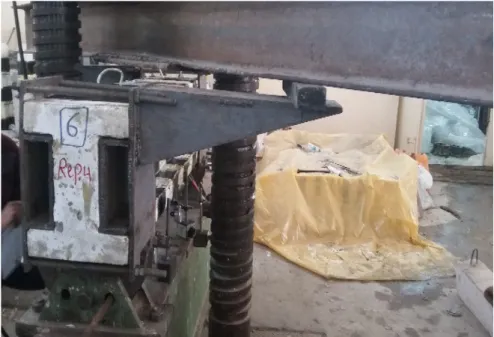
[16] (Figure 3). The special clamping loading frame at each end of the beam used in this research is shown in Figure 4. This frame consists of two large steel clamps, which work as arms for applied torque with separated faces to connect them over the sample by large bolts. Four bolts were used for each arm. This frame is made of thick steel plate (12 mm) with two steel shafts attached by welding. This final shape is similar to a bracket. These arms were capable of pro-viding a maximum eccentricity of (500 mm) with respect to the longitudinal axis of the beam. In order to get pure torsion, the center of support should coincide with the center of the moment arm. The steel girder of (300 mm) depth and (3 m) length was used to transmit the loads from the center of the universal ma-chine to the two arms (pure torsion). In addition, two lines load were used to transmit the load of bending (combined stresses) as shown in Figure 4. All beams were tested under monotonically increasing torque up to failure; the load was applied gradually. For each (5KN) load increment, readings were acquired manually. The torque increased gradually up to failure of the beam.
5. Results and Discussion
5.1. Efficiency of Ultimate Torque and Angle of Twist
The efficiency of repairing can be defined as the ratio of repaired beams to its original strength (on percentage basis). The relationships between ultimate tor-que with angle of twist, for original and repaired beams are shown in Figure 5. For each specimen, the general relationship between ultimate torque and angle of twist behavior was approximately linear elastic until the first diagonal cracks. The experimental results to ultimate torque are shown in Table 5. These beams
DOI: 10.4236/eng.2018.104014 209 Engineering Figure 4. Arrangement of Beam Testing.
(a) (b)
(c) (d)
Figure 5. (a) Applied Torque—angle of Twist; (b) Applied Torque—angle of twist; (c) Applied Torque—angle of Twist; (d) Applied Torque—angle of Twist.
were studied by [16] under pure torque only.
The general test results show that the repaired beams strengthened with steel plate gain high efficiency in ultimate torsional strength over that of the unplated repaired beam (Rep. 1). Furthermore, the composite repaired beams that contain the opening in the web gave a lowest efficiency in ultimate torque more than re-paired beams without opening in the web where the openings are considered
DOI: 10.4236/eng.2018.104014 210 Engineering Table 5. Ultimate torque results of the experimentally tested beams.
Beam
No. Ultimate torque (KN∙m) Repaired original (%) Angle of twist (rad) Repaired original (%) (Repairing)Tcr/Tult %
B1 52.5 89.8 0.0122 100.07 43.64 Rep. 1 47.125 0.0131 B2 56.875 91.2 0.0136 100.06 61.69 Rep. 2 51.875 0.0145 B7 46.875 86.67 0.0092 100.02 45.54 Rep. 3 40.625 0.0094 B6 43.123 83.48 0.0079 100.03 42.95 Rep. 4 36 0.0081
zones the weakness of the repaired beams. The largest efficiencies at ultimate torques were recorded for the composite repaired beam (Rep. 2) without open-ing in web. It has shown an efficiency of (91.2%) compared with refer-ence-repaired beam (Rep. 1) and efficiency recorded was indicated in the re-paired beam (Rep. 1) with efficiency of (89. 8%). In addition to the gradual de-crease in efficiency of the ultimate of the reinforced, concrete composite to the repaired beams containing opening in the web. Where the decrease efficiency in ultimate torque in composite repaired beam (Rep. 3) with circular opening in center web was 86.67%, and it came after a decrease of the efficiency in ultimate torque the composite repaired beam (Rep. 4) with circular opening in side web (83.48%) as shown in Table 5.
The results show that there were similar relations between repaired and origi-nal beams. There was a small rise in angle of twist in the repaired beam com-pared to the originals one, up to failure. Beams (Rep. 1, Rep. 2, and Rep. 3 and Rep. 4) were repaired beams, which recorded an increase in the angle of twist at ultimate torque of 0.07 %, 0.06%, 0.02 % and 0.03 % respectively compared original beams. On the other hand, it is clear that the beams after repairing have the same behavior, and the cracks would appear at first time near the opening. At ultimate torque, Beams (Rep. 1, Rep. 2, Rep. 3 and Rep. 4) repaired beams recorded 100.07 %, 100.06%, 100.02% and 100.03 % respectively. As shown in
Table 5.
In view of the above, it can be concluded that the presence of steel plates in the repaired section gives best efficiency in the ultimate torsional resistance and the small rise in angle of twist for repaired beam. As well as the presence of opening in the web lead to a decrease of the efficiency in ultimate torsional where it affect the location opening in the web of the ratio ultimate torque. It can be noticed that the best location for the opening is within the center of the span.
5.2. Angle of Twist-Distance along Beam Curves
The relationship between the ultimate angle of twist with the distance along the beams for original and repaired beams is demonstrated in Figure 6. The results
DOI: 10.4236/eng.2018.104014 211 Engineering Figure 6. (a) Ultimate angle of Twist with Distance (mm); (b) Ultimate angle of Twist with Distance (mm); (c) Ultimate angle of Twist with Distance (mm); (d) Ultimate angle of Twist with Distance (mm).
show that there are similar relations between repaired and original beams. The solid repaired beams and repaired beam with central opening have a symmetric-al behavior symmetric-along the beam. The maximum angle of twist occurs at the beginning of the beam (when support) and the gradually decreased to zero approximately at the mid span, then the angle of twist began to increase gradually but in oppo-site direction (reverse clockwise) until reaching the maximum value at the be-ginning of the beam from the other end.
It can be observed that the behavior along the repaired beam with opening at a third span seems unsymmetrical. The maximum angle of twist occurs at the beginning of the beam and the gradually decreased to approximately zero at the third span, where opening location exists. Then, the angle of twist began to in-crease gradually but in opposite direction until reaching to the maximum value at the beginning of the beam from the other end.
From the results obtained, it can be concluded that the critical angle of twist gradually decreases closer to the mid distance and gradually increases the closer supported in both directions. It is noteworthy to mention that this technique is new and for this reason no comparison can be carried out with other techniques.
5.3. Crack Pattern
All the reinforced concrete beams were tested under pure torsion loading and failed in torsion. The crack pattern and modes of failure for original and re-paired beams are shown in Figure 7. The angle of the first crack was close to 45
DOI: 10.4236/eng.2018.104014 212 Engineering Figure 7. (a) Unrepaired composite beam without opening and plate, B1; (b) Repaired of composite beam without opening and plate, Rep. 1; (c) Unrepaired composite beam without opening with plate, B2; (d) Repaired of composite beam without opening with plate, Rep. 2; (e) Unrepaired composite beam with central opening with plate, B7; (f) Re-paired of composite beam with central opening with plate , Rep. 3; (g) UnreRe-paired com-posite beam with opening at third span with plate, B6; (h) Repaired of comcom-posite beam with opening at third span with plate , Rep. 4.
degree in each case. The mode of failure of repaired beams was an extensive di-agonal concrete crack (torsional spiral cracks).
6. Conclusions
Based on the results obtained from the experimental work, the following conclu-sions can be stated:
1) The repaired beams give high efficiency in ultimate torsional strength, and this means the adopted technique gives good torsional strength.
DOI: 10.4236/eng.2018.104014 213 Engineering
2) Presence of openings in web decreases the efficiency the ultimate strength of composite repaired beams.
3) According to the ultimate torque, the best location for the opening is within the center of the span.
4) The angle of twist gradually decreases from the supports to the mid dis-tance of the beam.
5) There was a small increase in the angle of twist in the repaired beam com-pared to the originals at the supports.
6) This technique of repairing is the fastest way to rehabilitate the I-section beam is in place without the need for any cranes or jacks.
7) All the beams can be repaired and regain large amount of its strength by using the present technique of repairing by CFRP.
References
[1] Kim, G., Sim, J. and Oh, H. (2008) Shear Strength of Strengthened RC Beams with FRPs in Shear. Construction and Building Materials, 22, 1261-1270.
https://doi.org/10.1016/j.conbuildmat.2007.01.021
[2] Buyukozturk O., Gunes O. and Karaca E. (2004) Progress on Understanding De-boning Problems in Reinforced Concrete and Steel Members Strengthened Using FRP Composites. Construction and Building Materials, 18, 9-19.
https://doi.org/10.1016/S0950-0618(03)00094-1
[3] Shit, T. (2011) Experimental and Numerical Study on Behavior of Externally Bonded RC T-Beams Using GFRP Composites. Master’s Thesis, Department of Civ-il Engineering, National Institute of Technology, Rourkela.
http://ethesis.nitrkl.ac.in/2913/1/trishanu_thesis.pdf
[4] Tan, K.Y. (2003) Evaluation of Externally Bonded CFRP System for the Streng-thening of RC Slabs. Master’s Thesis, University of Missouri-Rolla, Center for In-frastructure Engineering Studies, Missoouri.
https://scholarsmine.mst.edu/masters_theses/2331/
[5] Ekenel, M., Stephen, V., Myers, J.J. and Zoughi, R. (2004) Microwave NDE of RC Beams Strengthened with CFRP Laminates Containing Surface Defects and Tested Under Cyclic Loading. Electrical and Computer Engineering, University of Mis-souri-Rolla, Rolla, 1-8.
http://www.ndt.net/article/wcndt2004/pdf/civil_structures/90_myers.pdf
[6] Silva, M. and Biscaia H. (2008), Degradation of Bond between FRP and RC Beams.
Composite Structures, 85, 164-174.
https://doi.org/10.1016/j.compstruct.2007.10.014
[7] Ilki, A. and Kumbasar, N. (2002) Repair and Strengthening of Damaged Reinforced Concrete Members by Carbon Fiber Reinforced Polymer Composites. Teknik Dergi Tech. Turkish Chamber of Civil Engineers, 13, 2597-2616.
https://www.researchgate.net/publication/293384073_Repair_and_strengthening_of _damaged_reinforced_concrete_members_by_carbon_fiber_reinforced_polymer_c omposites
[8] Adhikary, B.B., ASCE, M. and Musuyoshi, H. (2004) Behavior of Concrete Beams Strengthened in Shear with Carbon-Fiber Sheets. Composites Construction, 8, 258-264. https://doi.org/10.1061/(ASCE)1090-0268(2004)8:3(258)
DOI: 10.4236/eng.2018.104014 214 Engineering
Slovak Journal of Civil Engineering, 1-9.
https://www.svf.stuba.sk/buxus/docs/sjce/2009/2009_1/file5.pdf
[10] Bukhari, A.I., Vollum, L.R., Ahmad, S. and Sagaseta, J. (2010) Shear Strengthening of Reinforced Concrete Beams with CFRP. Magazine of Concrete Research, 62, 65-77. https://doi.org/10.1680/macr.2008.62.1.65
[11] Ahmed, A.S. and Saad, R.H. (2016) Behavior of Composite I-Section Modified Reactive Powder Concrete Beams with Ultimate Torque. Journal of Engineering and Sustainable Development, 20, 55-67.
[12] Central Organization for Standardization and Quality Control (1984) Iraqi Specifi-cations Number 5, Portland Cement. Baghdad, 8.
[13] Central Organization for Standardization and Quality Control (1984) Scrap of Nat-ural Resources Used in Concrete and Construction Baghdad, Iraq.
[14] ASTM-C494-05, American Society for Testing and Material (2005) Standard Speci-fication for Chemical Admixtures for Concrete.
https://compass.astm.org/Standards/HISTORICAL/C494C494M-05.htm
[15] ASTM C1240-03 American Society for Testing and Materials (2018) Standard Spe-cification for Use of Silica Fume as a Mineral Admixture in Hydraulic-Cement Concrete, Mortar, and Grout.
https://compass.astm.org/download/C1240-03.5161.pdf
[16] Ahmed, A.S. (2017) Behavior of Repaired Composite Modified Reactive Powder Concrete I Section Beams with Opening Under Pure Torque. Journal of Engineer-ing and Sustainable Development, 21, 39-50.
[17] Zararis, P. and Penelis, G. (1986) Reinforced Concrete T-Beams in Torsion and Bending. American Concrete Institute Journal, 83, 145-155.