Morphological Characterization of
Primary Austenite in Cast Iron
Juan Carlos Hernando
Department of Materials and Manufacturing
SCHOOL OF ENGINEERING, JÖNKÖPING UNIVERSITY Jönköping, Sweden 2017
Licentiate Thesis
Morphological Characterization of Primary Austenite in Cast Iron
Juan Carlos Hernando Department of Materials and Manufacturing School of Engineering, Jönköping University SE‐551 11 Jönköping, Sweden Juan‐Carlos.Hernando@ju.se Copyright © Juan Carlos Hernando Research Series from the School of Engineering, Jönköping University Department of Materials and Manufacturing Dissertation Series No. 23, 2017 ISBN: 978‐91‐87289‐24‐8 Published and Distributed by School of Engineering, Jönköping University Department of Materials and Manufacturing SE‐551 11 Jönköping, Sweden Printed in Sweden by Ineko AB Kållered, 2017i
ABSTRACT
Automotive industry products portfolio includes a wide variety of complex‐shaped cast iron products, such as truck engine components, that need to withstand a constant trend of higher demands, especially urged by stricter environmental regulations on emissions. Combined with this continued demand on properties improvement, cast iron industry faces a process problem related to the lack of understanding of solidification and mechanisms behind defect formation.
Casting products are highly affected by the product design and the manufacturing method itself, which governs the final microstructure and hence the final mechanical properties. Wall thickness of the moulding material strongly influences the solidification time, varying the microstructural coarseness, resulting in a component with different properties depending on the local shape of the casting.
The main objective of this work is the characterization of the primary austenite microstructure and its coarsening process, which has been poorly documented in cast iron literature, to allow the prediction and control of these microstructural features present in the casting.
The microstructural evolution of the primary austenite in hypoeutectic lamellar graphite iron (LGI) is studied under isothermal coarsening conditions. The dendritic microstructure suffered major morphological changes that included dendrite fragmentation, globularization, and coalescence. Empirical relations based on morphological parameters are introduced to predict the microstructural evolution of primary austenite. A novel technique for colour‐etching and semi‐automatic image analysis for the characterization of quenched dendritic microstructures in cast iron is presented. A new experimental technique for production of graphitic iron with varying nodularity is presented as a solution to control the production of compacted (CGI) and spheroidal graphite iron (SGI) under laboratory conditions. The nodularity evolution is controlled as a function of the holding time and the residual Mg, allowing the study of the primary solidification and primary microstructures of hypoeutectic CGI and SGI in future investigations. Keywords: Lamellar Graphite Iron, Solidification, Primary Austenite, Microstructure Evolution, Dendritic coarsening, Compacted Graphite Iron, Magnesium Fading, Nodularity.
ii
iii
ACKNOWLEDGEMENTS
I would like to express my sincere gratitude to:
My supervisor Attila Diószegi, for giving me this opportunity, his trust, guidance, support and extensive knowledge on cast iron. For his endless scientific curiosity, a continuous source of inspiration for my work. Björn Domeij, for his friendship, support, and appreciated advice and discussions. Daniel González, for his friendship, enthusiasm, and help with the experimental work. Toni Bogdanoff for his altruistic and enthusiastic help and technical assistant. Caterina Zanella for her valuable help, and fruitful discussions. Ehsan Ghassemali for his valued assistance and comments.
Paula García‐Caro, Carlos Martínez‐Lage and José Manuel Amieva for their contribution in the experimental work.
Lucian Vasile Diaconu for his support and assistance during the experimental castings.
Jörgen Bloom for his assistance during the experimental castings.
Esbjörn Ollas, Peter Gunnarsson and Lars Johansson for their work on the experimental equipment, and help in the workshop. Salem Seifeddine and Vasilios Fourlakidis for their good advice over these years. All my colleagues and friends at the department of Materials and Manufacturing and at the School of Engineering. Vinnova for financially supporting the projects CastDesign and Spofic II. All the involved industrial partners Scania CV AB, Volvo Group AB, SinterCast AB, and Swerea SWECAST, for their valuable support and contribution to this work.
My beloved family for their constant love and support. Especially to Bea for her endless inspiration, patience, and love.
Juan Carlos Hernando Jönköping, April 2017
v
SUPPLEMENTS
The following supplements constitute the basis of this thesis:
Supplement I J.C. Hernando, A. Diószegi; An Overview of Isothermal
Coarsening in Hypoeutectic Lamellar Cast Iron.
Presented at TMS 2015, March 15th‐19th, Orlando, Florida, USA. Published in Advances in the Science and Engineering of Casting Solidification, John Wiley & Sons, Inc. (2015): pp. 295‐302. Reprinted by Springer International Publishing (2016): pp. 295‐302.
J.C. Hernando was the main author. A. Diószegi contributed with advice regarding the work.
Supplement II J.C. Hernando, E. Ghassemali, A. Diószegi; The
Morphological Evolution of Primary Austenite During Isothermal Coarsening. Manuscript. Submitted for journal publication. J.C. Hernando was the main author. E. Ghassemali assisted with EBSD analysis. A. Diószegi contributed with advice regarding the work. Supplement III B. Domeij, J.C. Hernando, A. Diószegi; Quantification of Dendritic Austenite After Interrupted Solidification in a Hypoeutectic Lamellar Graphite Iron. Metallography, Microstructure, and Analysis, 2016, 5, 28‐42.
B. Domeij was the main author. J.C. Hernando designed and assisted during experimental work, analysis of results and advice regarding the work. A. Diószegi contributed with advice regarding the work.
vi
Supplement IV J.C. Hernando, B. Domeij, A. Diószegi; Influence of Ti
and Mo additions on the isothermal coarsening process of primary austenite in Lamellar Graphite Iron. Manuscript. Abstract accepted for presentation at the 5th Decennial International Conference on Solidification Processing, Old Windsor, UK, 25th‐28th July 2017.
J.C. Hernando was the main author. B. Domeij helped with experimental work, analysis of results and advice regarding the work. A. Diószegi contributed with advice regarding the work.
Supplement V J.C. Hernando, B. Domeij, D. González, J.M, Amieva, A.
Diószegi; New Experimental Technique for Nodularity and Mg Fading Control in CGI Production on Laboratory Scale.
Manuscript. Submitted for journal publication.
J.C. Hernando was the main author. B. Domeij helped with experimental work, analysis of results and advice regarding the work. D. González and J.M. Amieva helped with experimental work. A. Diószegi contributed with advice regarding the work.
vii
TABLE OF CONTENTS
CHAPTER 1INTRODUCTION ... 1 1.1 BACKGROUND ... 1 1.2 CAST IRON ... 1 Carbon equivalent ... 3 Classification ... 3 1.3 CAST IRON SOLIDIFICATION ... 5 Primary solidification ... 5 Eutectic Solidification ... 9 1.4 STATE OF ART ... 10 Gap between previous research and the present study ... 10 CHAPTER 2RESEARCH APPROACH ... 13 2.1 PURPOSE AND AIM ... 13 2.2 RESEARCH DESIGN ... 13 Research perspective... 13 Research questions... 14 Research strategy ... 15 2.3 MATERIAL AND EXPERIMENTAL PROCEDURE ... 16 Materials ... 16 Experimental procedure ... 16 2.4 CHARACTERIZATION... 20 Sample preparation ... 20 Colour etching ... 20 Microstructure evaluation ... 20 Microstructural quantitative characterization of the coarsening process ... 21 Graphite Characterization ... 22 CHAPTER 3SUMMARY OF RESULTS AND DISCUSSION ... 23 3.1 CHARACTERIZATION OF COARSENING PROCESS OF THE PRIMARY AUSTENITE ... 23 Qualitative description of the coarsening process of the primary austenite ... 23 Quantitative characterization of the coarseness of the primary austenite ... 26 Novel characterization technique for dendritic austenite in quenched samples ... 31 Modification of the coarsening process of the primary austenite by alloying ... 31 3.2 NODULARITY AND MG FADING CONTROL IN CGI AND SGI PRODUCTION ... 33 Effect of holding time on nodularity ... 33 Effect of holding time on cooling curves ... 35 Effect of holding time on chemical composition ... 35 Effect of holding time on residual and free magnesium ... 36 Relation between magnesium fading and nodularity ... 36 CHAPTER 4CONCLUSIONS ... 39 CHAPTER 5FUTURE WORK ... 41 REFERENCES ... 43 APPENDED PAPERS ... 491 CHAPTER 1
INTRODUCTION
CHAPTER INTRODUCTION
The purpose of this chapter is to introduce the reader to some important definitions and concepts related to cast iron alloys that will be used in the following chapters. The chapter starts with a small introduction on cast iron alloys and continues with a short description of their solidification process.1.1
BACKGROUND Casting is one of the oldest manufacturing methods for producing complex shapes for applications ranging from decorative parts to engineering components. Based on a solidification process, casting remains one of the most important commercial processes for many materials[1], with an increasing global production during the last 6 years, where global economy almost stagnated [2]. Cast parts can be found in approximate 90% of manufactured goods and equipment [3], including critical components for aircraft and automobiles, home appliances and medical equipment. Iron casting have been known and used for more than 2500 years [3]. The wide range of mechanical and physical properties of cast iron, associated with its competitive price, makes cast iron a very important engineering material with numerous technological applications. Present in a wide variety of parts, we find cast iron in general machinery pieces, railroad accessories and many other elements. One of the largest users of cast iron is the automotive industry, using cast iron to manufacture engine blocks, cylinder heads or piston rings among many other components [4].1.2
CAST IRONThe term cast iron refers to the multicomponent Fe‐C based alloys that solidify with an eutectic solidification and usually contain more than 2 wt.% of C. Using this definition we can easily distinguish cast irons and steel, which has a lower carbon content and solidifies according to the metastable Fe‐C diagram, while cast iron solidifies on the stable Fe‐C diagram shown in Figure 1 [5].
The eutectic point on this Fe‐C binary diagram is assumed at 4.3 wt.% C. Cast irons with C content below 4.3% are hypoeutectic irons and the solidification will start with the crystallization of the austenite phase. On the contrary, cast irons with a C content above 4.3% are hypereutectic irons and the solidification starts with crystallization of graphite. In both cases, the solidification process ends below the eutectic temperature, where the eutectic reaction occurs and the remaining liquid transforms into austenite and graphite.
Commercial cast iron alloys include, however, the addition of several chemical elements in the composition. Alloying elements are added to the melt to control the
2
solidification process and change the properties of the material. The main alloying element is Si, usually in a content between 1 to 3 wt.%. Si promotes the solidification according to the stable Fe‐C diagram having a strong graphitizing effect [6], increases the difference between the higher eutectic solidification temperature of the stable diagram compared to that of the metastable diagram [7], increases fluidity and reduces hardness and shrinkage [8]. Due to this strong influence, some authors even consider cast irons as ternary Fe‐C‐Si alloys.
Cast iron alloys contain many other minor alloying elements depending on the required properties. Common elements found in cast irons with engineering applications are P, S, Mn, Ni, Sn, Cu, Cr and Mo.
Some of these alloying elements, such as S, Al, Sn or Cu, are known as graphitizers for their ability to promote the formation of graphite by reducing the solubility of carbon in the eutectic iron‐carbon melt. On the other hand, elements such as, Ca, Mn, Mo, Ti or Cr retain carbon in the form of iron carbides forming metallic carbides in the solidification process. These elements are known as carbide stabilizers [7].
Figure 1: The stable binary Fe‐C phase diagram. Calculated with Thermo‐Calc 2016b and TCFE7 database [9].
3 Carbon equivalent The concept of carbon equivalent (CE) is used in cast iron to account for the effect of the alloying elements on solidification regarding the eutectic reaction. CE is defined considering the amount of carbon, silicon and phosphorus as main elements affecting the eutectic reaction [10]: CE %C 1 3%Si 1 3%P 1
Accounting the effect of these elements on the solidification process, CE is used, instead of the single C content, to define hypoeutectic or hypereutectic compositions. Despite its general use in foundry practice, it must be noted that the same CE can result on different properties depending on many other factors, such as the rest of alloying elements or different cooling conditions. Classification Nowadays, the most extended way to classify cast irons is by specifying the dominant morphology of the graphite phase in the microstructure. The morphology of the graphite determines three main families [3, 11]:
‐ Lamellar graphite iron (LGI), where the graphite adopts the shape of lamellas or flakes. This type of iron is also known as grey iron.
‐ Spheroidal graphite iron (SGI), where the predominant graphite shape is spheroidal, also called graphite nodules. This variety is also referred as to nodular iron.
‐ Compacted graphite iron (CGI), where the graphite particles adopt an intermediate compacted worm‐like shape, also called vermicular graphite. Another possible classification criterion is based on the dominant phase formed in the metallic matrix after the eutectoid transformation, e.g. ferritic or pearlitic iron. (a) (b) (c) Figure 2: Principal graphite forms in cast iron materials: (a) lamellar graphite (LG), (b) spheroidal graphite (SG), and (c) compacted graphite (CG) [12].
4 (a) (b) Figure 3: Microstructures of cast iron samples under optical microscopy after subjected to a colour etching process with Motz’s reagent showing: (a) spheroidal graphite (SG) and compacted graphite (CG) surrounded by ferrite, and (b) lamellar graphite (LG) in a pearlitic matrix. The graphite morphology confers different physical and mechanical properties to the three main families of cast iron alloys. For instance, SGI has higher mechanical properties favoured by the nodular particles, while LGI has good thermal properties due to the sharp graphite particles. CGI as a transitional behaviour, due to the intermediate character of the vermicular graphite shape, shows an excellent compromise in thermal and mechanical properties.
Different methods have been used to characterize the different industrial grades among the main cast iron families. Nowadays, due to the existing image analysis tools, the concept of nodularity is widely applied by cast iron users and industry and it is defined by various standards, e.g. ASTM [13] and ISO [14]. Nodularity uses the concept of the roundness of the graphite particles, defined as:
Roundness 4∗ 2
Where A is the area of the particle and
is the area of a circle with a diameter equal to the maximum distance between two boundary points of the particle,
.
Graphite nodules are those graphite particles with more than 0.625 roundness, considering intermediate particles those with a roundness between 0.525 to 0.625. Measuring the roundness of every graphite particle viewed on a two‐dimensional polished surface, the nodularity is calculated by ISO according to: Percent Nodularity 100 ∗ ∑ A 0.5 ∗ ∑ A ∑ A 3 The classification according to ISO standard is that CGI should have less than 20% nodularity with no presence of lamellar graphite particles.5 The classification of LGI is based on the lamellar graphite distribution in the microstructure. The different distributions are named from A to E and are schematically represented in Figure 4 [12]
Figure 4: Different graphite distribution types in LGI [12].
1.3
CAST IRON SOLIDIFICATIONSolidification is the phase transformation from liquid to solid. During this transformation, the atoms in the melt start to rearrange from short‐range order in the liquid phase to regular positions on a crystallographic lattice. The atoms need to release energy in order to rearrange [15, 16]. This energy is released in the form of extracted heat via the surrounding walls of the mould.
The final microstructure and thus the properties of cast irons are highly influenced by the metallurgical conditions during the solidification. Chemical composition, modification treatment, inoculation, cooling rate and atmosphere in the furnace are some of the variables that influence the final casting properties [3, 16, 17].
Primary solidification
The solidification process of a hypoeutectic cast iron alloy can be divided into two different events: the primary solidification and the eutectic solidification [3, 4]. 1.3.1.1 Nucleation of primary austenite
According to the thermodynamic equilibrium diagram, the primary solidification starts below the liquidus temperature with the nucleation of the primary austenite. Nucleation requires certain undercooling in the melt for the creation and growth of nuclei with a critical radius. The higher undercooling will facilitate an easier event of nucleation. The maximum undercooling observed at commercial castings is not sufficient to trigger a homogenous nucleation event and therefore, all nucleation events during cast iron solidification are assumed as heterogeneous [3, 17]. The presence of impurities and the surface of the mould wall are preferential sites for the nucleation of the primary austenite. After the mould filling, the mould wall is the coldest part of the system and can generate the sufficient undercooling for the first nucleation to take place.
It has been demonstrated that the effectiveness of a compound acting as substrate in heterogeneous nucleation is related to the lattice disregistry between the nucleating agent and the nucleated phase [18]. On that sense, the most effective nucleating agent for primary austenite should be pure iron particles as they have the same crystal structure [19]. Other compounds acting as effective nucleants for austenite precipitation are silicon carbide (SiC) [19], or graphite in the case of hypereutectic
6
irons [20]. Despite the large lattice disregistry with austenite, silicon dioxide powder (SiO2), was also found to be an effective inoculant [21].
1.3.1.2 Growth of primary austenite
The stable nuclei of austenite continue to grow in the form of dendrites, known as primary grains or primary crystals [22, 23]. The dendrites are composed by a main arm (primary arm) that branches into lateral arms (secondary arms and tertiary arms) if the distance with neighbouring dendrites is sufficient [15].
Figure 5: Schematic representation of a dendrite [4].
The primary crystals will first grow favourably oriented to the heat extraction, perpendicular to the mould wall towards the centre of the casting and forming a structural region known as columnar zone [1]. This columnar grow will form the skeleton or skin of the casting which has great influence on defect formation [24]. Figure 6: Schematic representation of columnar dendritic growth from the surface of the mould. The dendrite grains are form by one dendrite per grain. All dendritic arms within a dendrite have a unique crystallographic orientation [17]. Additionally, equiaxed crystals will be nucleated on impurities floating in the melt if the critical undercooling is reached ahead of the columnar growth. Growing in six orthogonal directions, due to the anisotropy of the face centred cubic crystal of the
7 austenite, these crystals constitute the second growth type and will create a region in the casting known as the equiaxed zone [25]. Each of these crystals is formed by a unique dendrite of the same crystallographic orientation [15, 22]. Both types of growth occur until the austenite dendrites impinge on each other and block their growth, reaching the dendritic coherency, defining the final macrostructure of the casting [26]. Dendritic coherency doesn’t occur simultaneously throughout the full macrostructure but during a time interval. Figure 7. Binary Fe‐C‐Si phase diagram at 1.8% Si, obtained using Thermocalc® with the TCFE6 database (left). Typical cooling curve and the schematic illustration of the solidification process and structure (right) [27].
1.3.1.3 Coarsening of primary austenite
After the macrostructure of the casting is defined, when dendrite coherency is reached, the main growth mechanism for the primary dendritic structure consists on a coarsening process.
Figure 8: Micrograph of a coherent dendritic microstructure in the liquid‐solid region in cast iron.
The coarsening process, also known as Ostwald ripening, is a diffusion controlled phenomenon that minimizes the interfacial free energy of a liquid‐solid system. The initial dendritic structure is not in thermodynamic equilibrium due to its large interfacial area [28]. This diffusional process includes dissolution and reprecipitation
8
of the solid phase making the overall length scale of the system increasing and the total interfacial area decreasing [29]. This mass diffusion process is associated with the curvature dependence of the equilibrium concentration, represented by the Gibbs‐Thomson equation (4) [28]:
4
where C is the composition of the liquid at the solid‐liquid interface, C is the composition at the flat interface, is the capillary length, which is dependent on material parameters and H is the mean interfacial curvature. Coarseness of dendritic structures is commonly described in cast iron literature in terms of the secondary dendrite arm spacing (SDAS) shown in Figure 6 [4, 15, 30, 31]. However, it has been shown in other alloys, that severe morphological changes might occur during the dendritic coarsening process [32]. The smaller arms are re‐melted at expenses of the large ones [33], proceeding with a dendritic fragmentation [34]. The dendritic structure is no longer existing and the detached particles adopt a globular shape [35]. Furthermore, these globular particles will eventually coalesce into a larger globular particle to minimize the interfacial area per volume [36]. Under these conditions, the application of SDAS to represent the coarseness of the microstructure is not applicable and other shape independent parameters have been introduced in the literature [32, 37].
Previous investigations have introduced the study of the evolution of primary austenite under dynamic coarsening during the sequence of solidification of hypoeutectic LGI [37]. In these conditions, the continuous precipitation of solid phase until the end of solidification, first during the primary solidification and later during eutectic solidification, does not allow a thorough study of the evolution of the dendritic microstructure, which is influenced on its development by the eutectic precipitation. A common solution to solve this problem applied in the investigation of other alloys is the study of the coarsening process under isothermal conditions [38]. (a) (b) Figure 9: Three‐dimensional reconstructions of coarsened Al–Cu samples: (a) 10 min and (b) 3 weeks [38]. The effect of several alloying elements, such as B, Ti, Zr, Al and Bi, have been reported to have certain influence on the primary solidification and the primary dendrite morphology of hypoeutectic grey cast iron. Previous works suggested a significant refining effect on the austenite promoted by these elements [23, 39‐41]. However,
9 the characterization of the microstructural coarseness was described more on qualitative terms, such as “short”, “random” and “loosely packed”, rather than on quantitative measurements.
Eutectic Solidification
During dendritic growth, the interface composition of the austenite follows the liquidus line in the Fe‐C diagram shown in Figure 1, resulting in the rejection of the excess of carbon to the melt. Once the liquid reaches the eutectic composition and the required undercooling for its nucleation, the eutectic phase precipitates. In this eutectic phase, carbon precipitates as graphite. The eutectic solidification also starts with a nucleation event followed by a growth process.
1.3.2.1 Nucleation of graphite
The nucleation of graphite, assumed heterogeneous, occurs on pre‐existing inclusions in the liquid [42‐46]. For lamellar graphite, these inclusions are complex sulfides (Mn,X)S that previously nucleated on complex oxides of Al, Si, Zr, Mg and Ti [42, 43, 46]. On the other hand, it has been observed that spheroidal and compacted graphite have similar nucleation sites [11]. These nuclei are formed by complex Mg silicates (MgO.SiO2) that nucleated on the external layer of MgS and CaS sulfides [44]. 1.3.2.2 Growth of graphite The subsequent growth of graphite nuclei, determining the graphite morphologies presented in Figure 2 is primarily affected by two factors: the presence of surface active impurities in the melt, and the cooling rate during solidification of the alloy [3]. The effect of higher cooling rates is accepted to be promoting the formation of SGI. The influence of impurities can be divided into two categories [3]: a) reactive impurities, promoting SGI formation such as Mg, Ce, Ca, Y, and La, called compacting or spheroidizing elements, b) surface‐active impurities, which favour LGI formation, such as S, O, Al, Ti, As, Bi, Te, Pb, and Sb, called anti‐compacting or anti‐spheroidizing elements. The presence of these impurities affects the principal growth direction of graphite [47, 48]. In the case of LGI, dominant growth takes place along the A‐axis, while in SGI it occurs along the C‐axis. An intermediate situation takes place for CGI, since dominant growth direction continuously varies between the A axis and the C axis [47, 48].
10 The surface‐active impurities are absorbed on the prismatic face of the hexagonal graphite lattice, creating a non‐faceted interface, that requires low driving forces to grow, i.e. low undercooling, e.g. the case of LGI, while for SGI the growth on the faceted interface requires larger undercooling [11, 43, 45]. Reactive impurities are then added to the melt to scavenge the reactive impurities, specially O and S, and control graphite morphology in a nodularization treatment [3, 11]. The most common element used to this purpose is Mg, but Ce or RE metals are also used for this treatment [11]. The main purpose of this treatment is to reduce the oxygen activity in the melt, by formation of oxides, and control the graphite shape during solidification [50, 51].
The main problems associated to this nodularization treatment, that hinder the accurate control of the graphite morphology are:
a) the narrow window to produce CGI treatment over time: the abrupt transition in terms of Mg content from CGI to LGI is complex to control during production of CGI components, as shown in Figure 11 [52]. b) the fading of the nodularization treatment during production: Mg content fades over time if the melt is held at elevated temperatures [53]. Several expressions and different values for the fading rate of Mg with respect to time are reported in literature [53‐58]. Figure 11: Nodularity values depicted as a function of total Mg content. Vertical lines show the narrow CGI production region [52].
1.4 State of Art
Gap between previous research and the present study
From the literature review above it can be seen that we have acquired an extended knowledge on cast iron over the last decades, however, there are still several aspects and problems that remain unsolved in its solidification process. These are translated into daily problems for producers and user of cast iron. One of the research gaps that is identified, is the limited number of works studying the influence of the primary solidification, and primary austenite on the subsequent solidification process and final properties of the material.
11 The transformation of austenite during the eutectoid reaction, occurring around 730˚C, makes its characterization at room temperature not possible under a normal solidification process. Only etching techniques allow the observation of the former primary austenitic structures in the as cast microstructure [59, 60]. Special experimental techniques, like interrupted solidification experiments, are required to preserve the primary austenite at room temperature [61]. The characterization of the primary austenitic macrostructure is also complicated, where experimental treatments are required to partially retain the primary austenite, and reveal the primary grain structure [19, 22]. These experimental limitations hinder the investigation of the primary austenite since they are not available techniques for all researchers on the field. On the contrary, the presence of graphite is revealed after a basic polishing process. This fact promoted a great advance on the knowledge front on the eutectic solidification stage in cast iron, which was deeply studied by numerous researchers [42, 43, 45, 48, 62‐66].
Some researchers have investigated the growth characteristics of the primary phase, which has been demonstrated to influence the eutectic cell size, defining its final microstructure [67]. The dynamic coarsening of primary austenite in LGI has been recently measured in interrupted solidification experiments and correlated to the eutectic phase fraction and size scale [68]. On the same trend, recent results correlate the coarseness of the primary austenite to the mechanical response of the material [37] and the existence of defects such as shrinkage and metal expansion penetration [69, 70]. The major influence of the graphite in the properties of cast iron can never be ignored, but only promoting the front knowledge on the primary solidification to the same level, and clarifying its influence on the final microstructure, will allow a full optimization of the properties of cast iron components.
This study tries to enhance the knowledge on the primary solidification in LGI characterizing the mechanisms of the coarsening process of the primary austenite in LGI, responsible for the final morphology of the primary microstructure and thus related to the final properties. The evolution of the primary austenite during solidification, reported in the literature as subjective qualitative descriptions, requires quantitative parameters and empirical relations for its prediction.
At the same time, the study of the primary solidification on CGI and SGI remains poorly understood due to the limitations during production presented in this literature section. This work aims to present the required experimental tools to extend the study of the primary solidification to CGI and SGI hypoeutectic composition in future steps of this research.
12
13 CHAPTER 2
RESEARCH APPROACH
CHAPTER INTRODUCTION
This chapter describes the research methodology used in this thesis. The purpose and aim of the thesis are first described, followed by a description of the research materials, research methods, and research activities.
2.1
PURPOSE AND AIMAutomotive industry product portfolio covers an extensive variety of complex‐ shaped cast iron products, such as truck engine components. These components, need to endure a constant trend on higher demands, especially urged by severe environmental regulations on emissions.
The product design and the casting process, govern the final microstructure of the material and hence its final performance. Wall thickness of the moulding material strongly influences the solidification time, varying the coarseness of the microstructure, giving result to a component with different properties depending on the local shape of the casting.
A deeper understanding on the coarsening process of the primary austenite could improve the ability to predict the formation of some casting defects, such as metal expansion penetration and improve simulation tools to model the interdendritic feeding mechanisms after dendritic coherency of the primary austenite.
The aim of this research is to improve the knowledge and characterization tools of the primary austenite network and its coarsening process, a field that has been poorly documented in cast iron literature. The intended industrial contribution developed from this knowledge is to enhance prediction and control of this microstructural features present in the casting and contribute to an improvement in properties and reduction of defect formation.
2.2
RESEARCH DESIGN Research perspective Research in the discipline of material science is mostly based on deductive reasoning supported by empirical quantitative data. The use of a deductive reasoning approach transfers the argument from general principles to particular cases using hypothesis testing to validate the truth of the conclusion [71]. The research starts with the statement of the topic of interest and continues with an iterative information gathering process that will lead to the definition of a hypothesis. This hypothesis will later be validated or refuted by observations, data collection and analysis to state a general law based on empirical observations.14
Figure 5. Schematic representation of the applied research approach [71].
The importance of the literature review is crucial since it will help to narrow down the possible experimental variables to study, set limitations and identify the last trends on experimental techniques existing in the research community working with similar metallic alloys. This information is first retrieved, selected and evaluated. This process is iterative and it is constantly resumed if new relevant variables, relations or publications related to the research appear [72]. The information resources used were mainly online databases (Scopus and Web of Science) that granted access to journal and conference publications but also resources from Jönköping University library such as books and e‐books.
The experimental method is the main technique applied throughout this research. The main objective is to infer causation between solidification variables –such temperature, time, chemical composition, chemical composition‐ and the coarsening process of the primary austenite in cast iron.
Research questions
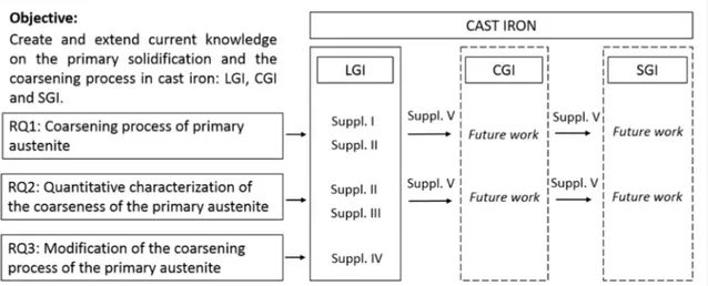
From the previous literature review, the general theory of solidification and the coarsening process in metallic alloys are studied. From this process is easy to conclude the technological importance of coarsening process in industrial metallic alloys. At the same time, there is a lack of literature about this topic of interest in one of the most important material family of metallic alloys, cast iron alloys which in contrast with other technical alloys, have received insufficient treatment in this topic in literature during last decades. The current research, therefore, tries to extend the knowledge on coarsening of the primary austenite in both LGI, CGI and SGI, the three main industrial types of cast iron alloys and tries to answer the following research questions: 1. What are the main mechanisms of coarsening in primary austenite in cast iron? The coarsening mechanisms of primary austenite in cast iron must be understood in order to control and predict its evolution.
2. Which are the most suitable parameters to establish a quantitative characterization of the coarseness of the primary austenite? The main parameters applied to coarsening characterization in metallic alloys are related to the solidification time. They should be applied to cast iron investigations to avoid ambiguous interpretation of the coarsening phenomena 3. Can we modify the coarsening process of the primary austenite through alloy selection? Some previous studies shown in the introduction reported an influence of several alloying elements on the primary austenite. The possibility to influence the coarsening process by means of alloying elements is also intended to be studied in this research.
15
Research strategy
In the previous section, it was introduced that the lack of appropriate experimental techniques and a common characterization terminology are some of the main problems that hinder the investigation of the primary solidification and primary austenite.
The purpose of Supplement I and Supplement II is to study the coarsening process of the primary austenite in cast iron by solving these limitations. The output of Supplement I is the description of an experimental technique enabling the study of the isothermal coarsening process and the creation of a qualitative model of the for this isothermal coarsening process referring to RQ1. Supplement II will include a quantitative characterization of the process, generating kinetic and morphological laws for coarsening mechanism in LGI, addressing RQ2.
After that, the experimental technique introduced in Supplement I and II, and the characterization improvements implemented Supplement III, are applied to the research problem stated in RQ3. Supplement IV studies the possible modification in the coarsening process of the primary austenite inferred by chemical composition variations, i.e. inclusion of alloying elements.
Oriented to improve a similar knowledge on primary solidification and primary austenite on CGI and SGI solidification, Supplement V presents a novel experimental technique allowing the production and characterization of CGI and SGI samples under laboratory condition. The results introduced in Supplements I, II and III will be applied to the characterization of the coarsening process of the primary austenite in SGI and CGI.
16
2.3
MATERIAL AND EXPERIMENTAL PROCEDUREMaterials
The experimental work performed in this thesis involves 8 alloys listed in Table 1. Material related to Supplements I and II is a hypoeutectic lamellar graphite iron, noted as Alloy L. The material for Supplement IV consists of 6 alloys with different contents of Mo and Ti added on a similar base hypoeutectic lamellar graphite iron. Supplement III is based on one of these alloys, Alloy Mo . Note that the composition listed here is the correct one and not the one specified in Supplement III. The last supplement, Supplement V, studies a rather different material compared to the previous ones and is based on a hypereutectic spheroidal iron, Alloy S.
Alloys L, Mo , Mo and Mo were produced in an industrial foundry, while the rest of the alloys were produced in an experimental foundry plant. The nodularization treatment in Alloy S was performed with FeSiMg. The chemical composition of each alloy listed in Table 1 was obtained using optical emission spectrometry (OES) on a rapidly solidified coin sample. All alloys were cast in furan sand moulds, in the shape of cylindrical specimens of Ø50 mm diameter. The cast cylinders were machined to cylindrical specimens of 38 mm diameter with a weight of 400 ± 0.5 g which yields an approximate height of 42 mm. Table 1: Chemical composition of the experimental materials. Measured using OES. CE=C+1/3(Si+P)
Alloy CE C Si Mn P S Cu Mo Ti Mg Fe
L 3.9 3.3 1.8 0.58 0.034 0.086 0.9 0.22 ‐ ‐ Bal. Mo 4.0 3.4 1.9 0.57 0.052 0.089 0.9 0.05 ‐ ‐ Bal. Mo 4.0 3.4 1.9 0.59 0.053 0.085 0.9 0.48 ‐ ‐ Bal. Mo 4.0 3.4 1.9 0.60 0.053 0.085 0.9 0.94 ‐ ‐ Bal. Ti 3.9 3.4 1.5 0.63 0.037 0.025 1.0 ‐ 0.05 ‐ Bal. Ti 3.9 3.4 1.5 0.61 0.034 0.027 1.1 ‐ 0.15 ‐ Bal. Ti 4.0 3.5 1.5 0.57 0.034 0.026 1.0 ‐ 0.41 ‐ Bal. S 4.7 3.9 2.6 0.64 0.030 0.010 0.8 ‐ ‐ 0.065 Bal. Experimental procedure The experimental work performed in this work is based on the re‐melting and re‐ solidification of the experimental alloys introduced above. Experiments, however, can be differentiated in two types, those experiments that study the primary solidification and the coarsening process of the primary austenite in hypoeutectic lamellar graphite iron, covered on Supplements I, II, III and IV; and the experimental work performed to introduce a new technique for production of CGI and SGI under
17 laboratory condition that will allow the implementation of the knowledge achieved in the previous supplements on the primary solidification in CGI and SGI.
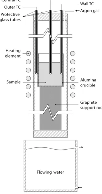
2.3.2.1 Experiments on primary solidification (Supplements I, II, III and IV) The machined specimens were subjected to a re‐melting process followed by a cooling process leading to a primary solidification event and a subsequent isothermal treatment. The whole process was conducted inside a vertical tube electrical resistance furnace under argon gas atmosphere to preserve the chemical composition of the alloy.
Figure 13: Re‐melting experimental equipment used in this research work.
The main details of the process can be summarized as follows. On preliminary experiments, the specimens were introduced into the chamber inside an alumina crucible and re‐melted in a heating cycle of 90 minutes from room temperature to 1723 K (1450 °C) and held for 30 minutes. The furnace was switched off and solidification process of the material started. The solidification process was recorded with two thermocouples for each alloy. One thermocouple was placed at the
18
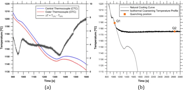
geometrical centre of the sample and a second one was in the same planar section of the sample but in contact with the wall of the crucible. The thermal coherency was identified as the maximum temperature difference between centre and wall thermocouple prior to eutectic solidification [73], shown in Figure 14 a. This thermal information allows the design of the isothermal heat treatment to study the isothermal coarsening process of the primary austenite.
(a) (b)
Figure 14: a) Cooling curve of alloy L and b) isothermal temperature profile for Supplements I and II.
After these preliminary experiments, the same re‐melting program was applied to the specimens, however, this time the solidification process was halted when the thermal coherency was reached and an isothermal temperature profile was added to the program, shown in Figure 14 b, and samples were isothermally coarsened for different times, resulting in final specimens with microstructure of varying coarseness. At the end of this isothermal time, the samples were immediately quenched by being dropped into flowing water to suppress the stable eutectic transformation and preserve the dendritic structure at room temperature. The different duration of the isothermal treatments performed on this investigation for each alloy is listed in Table 2. These time intervals were chosen to promote the full development of the coarsening process, including long times previously never studied for cast iron solidification.
Table 2: Duration of the isothermal treatment performed in investigations related to Supplements I, II and IV
Isothermal coarsening times (in minutes)
Alloy L 0 30 90 180 360 720 1440 2880 4320 5760 Alloys Mo , Mo , Mo 0 30 90 180 360 720 ‐ ‐ ‐ ‐
19 The thermocouples used for the preliminary experiments are calibrated type S (Pt/Pt+10%Rh) mounted in an alumina case which insulates the thermocouple wires, leaving only the welded joint accessible. The thermocouples are protected by glass tube to prevent direct contact with the melt. The thermocouples are connected to a commercial data acquisition system that records all the data measured by the thermocouple.
2.3.2.2 Experiments on nodularity and Mg-fading control in CGI production (Supplement V)
The aim of these experiments was to produce graphitic cast iron of the main three families with controlled graphite morphology, ranging from LGI to SGI. The experimental procedure was similar to the one previously described for the experiments of primary solidification. The main difference is that the holding time at 1723 K (1450 °C) was on this occasion varied to represent different initial solidification conditions in each experiment, and therefore to obtain samples with varying nodularities at the end of the solidification process depending on the holding time. The cooling process was continued until room temperature under the same conditions for all the experiments performed. The experimental set up was slightly modified from the one used in the previous experiments to introduce the stable argon gas flow of 4 l/min from the bottom part of the furnace’s chamber. The holding time was changed in 10 minutes’ increments as listed in Table 3. Table 3: Duration of the holding times performed in investigation related to Supplement V Alloys S H0 H10 H20 H30 H40 H50 H60 H70 H80 H90 H100 H110 H120 H130 H140 Holding time (min) 0 10 20 30 40 50 60 70 80 90 100 110 120 130 140
A series of quenching experiments was additionally performed to examine the chemical composition of the melt after the re‐melting process and before the start of the solidification process after different holding times, see Table 4. The sample was re‐melted at 1723 K (1450 °C) and held the correspondent time, but immediately after the end of the holding time, the sample was quenched into water to promote a white solidification and avoid graphite precipitation. This experimental series provided samples suitable for OES. Table 4: Quenching experiments performed in investigation related to Supplement V Alloys S Q0 Q10 Q20 Q30 Q60 Q110 Holding time (min) 0 10 20 30 60 110
20
2.4 CHARACTERIZATION
Sample preparationAfter all the re‐melting experiments, all the samples produced were sectioned approximately at their middle section, around 20 mm from the bottom end. Samples were mounted in thermosetting resin and ground with SiC papers of different granulometry from a grit size of P80 (FEPA) to P2000 (FEPA) to subsequently start a mechanical polishing process with solutions containing diamond particles of 3 and 1 µm applied on satin woven acetate and short synthetic nap clothes correspondingly. For samples requiring graphite characterization, in Supplement V, this standard process produced a good result regarding graphite retention, but some graphite particles were partially covered by ferrite and could lead to a wrong interpretation. To solve this problem an additional polishing step with an oxide slurry was manually applied for graphite characterization.
Quenched samples produced for chemical composition analysis in Supplement V, were grounded to produce a flat surface suitable for OES. OES was performed with a Spectro SPECTROMAXx stationary metal analyzer. A minimum of 3 measurements per sample were performed. Colour etching Samples from Supplements I and II were etched at 381 K (108 °C), for approximately 2 minutes with Motz’s reagent [60], consisting of 10 g NaOH, 40 g KOH, 10 g picric acid and 50 ml of distilled water. This process made the primary austenite discernible from the eutectic liquid.
Application of the new tinting technique for quenched samples introduced in Supplement III [61], made the dendrites distinguishable after additional polishing steps of 20 seconds with a l µm diamond suspension for samples related to Supplement IV. This new method supposes a considerable reduction in processing time and eliminates chemical hazards to the operator compared to the use of Motz’s reagent.
Microstructure evaluation
The microstructures generated after sample preparation were studied by optical microscopy (Olympus GX71F). For samples related to Supplement I, micrographs capturing the whole cross‐section of the specimen were taken.
For samples from Supplement II, III and IV, the colour‐etched micrographs were transformed into binary images, where dendrites were represented as black colour objects. A Wacom Cintiq interactive pen display was used for this purpose. Whilst in Supplement II this operation was done manually, in Supplements III and IV a semi‐ automatic technique was applied with a significant reduction in processing time.
21
(a) (b)
Figure 15: a) Colour etched micrograph from Supplement II and b) its equivalent binary image.
The electron backscatter diffraction (EBSD) analysis of representative samples from Supplement II, i.e. after 0 min, 30 min, 6h, 24h, and 48 h of isothermal treatment was carried out by an EDAX detector mounted on a JEOL 7001F scanning electron microscope. Using an accelerating voltage of 20 kV and a step size of 1 µm, an approximate area of 0.6 mm × 3.3 mm was scanned for each sample. EBSD maps were further analysed using TSL‐OIM v.7.3 package.
Microstructural quantitative characterization of the coarsening
process
The microstructure of the samples from Supplements II, III and IV was quantitatively characterized in terms of stereological relations using Olympus Stream Motion Desktop software 1.9.1. in the binary images. The main stereological parameters used in Supplements II, III and IV are: the modulus of primary austenite, M , the specific inverse surface area, S , of the primary austenite phase and the hydraulic diameter of the interdendritic phase, D and can be calculated as follows [37]: M / / 5 S / / 6 D ⁄ ⁄ ⁄ 7
where is the total area of the austenite, is the perimeter of the austenite phase and the total area measured. The complete mathematical derivation of the parameters can be found elsewhere [37, 74].
22 The distance to the nearest austenite particle, D , is also characterized. It measures the distance between the centre of gravity of one austenite particle and the centre of gravity of all its surrounding neighbours and returns the smallest distance. For Supplements I and II, SDAS characterization was performed on a minimum of 7 measurements per sample with at least 3 parallel secondary arms per measurement. The mean value of the mean curvature (H) of the primary austenite particles was also estimated [75‐77]. To estimate H, a test line must be swept across the planar section of interest to count the number of interceptions with particles , and the number of particles per unit area . Then H can be estimated by [78]: H / 8 Where is the number of interceptions with particles per unit length and not the number of particles intercepted. 2.4.4.1 Sampling Area The extent of the area analysed has a direct impact on the reliability of the results. The smaller the size of the analysed the higher the standard deviation of the measurements. On a similar investigation [79], is it recommended the selection of a sampling area based on the coarser microstructure. In the current work, the sampling area for microstructural characterization is rather high compared to other investigations. Two areas of 19 mm2 extracted from the central section of each sample are used for this purpose. Because of the severe microstructural changes observed at longer coarsening times, an extra area of 19 mm2 was analysed to improve the reliability of the characterization of the samples coarsened for longer times. The analysis of such a large area for each sample will provide strong statistical support for the quantitative analysis.
Graphite Characterization
In Supplement V, the graphite is characterized using the concept of nodularity described in the introduction section, Equation 3, and applying ISO [14] and ASTM standards [13]. Microstructural features smaller than 10 µm are considered micro porosities, defects due to sample preparation or particles that should be excluded from graphite analysis. Graphite particles in contact with the limits of the image are not considered in the analysis. A preliminary analysis of the microstructures revealed a large graphite particle size, enabling the use of a low magnification, allowing to characterize a much larger surface area than required in the standards. A minimum of 40 micrographs for each specimen is used for this purpose, representing a minimum area of 137 mm2 for each specimen, improving result soundness.
23 CHAPTER 3
SUMMARY OF RESULTS
AND DISCUSSION
CHAPTER INTRODUCTION
In this chapter, the main results of the appended papers are summarised and discussed. This chapter is divided into main two parts: the characterization of the coarsening of the primary austenite in LGI, and the description of nodularity and Mg‐ fading control in CGI and SGI production.
3.1 CHARACTERIZATION OF COARSENING
PROCESS OF THE PRIMARY AUSTENITE
The characterization of the coarsening process of the primary austenite in hypoeutectic lamellar iron comprises the main body of this research work. This topic is treated in Supplements I, II, III and IV.
Qualitative description of the coarsening process of the primary
austenite Supplement I approached for the first time the study of the isothermal coarsening of the primary austenite in cast iron. This research article tries to answer RQ1, using a qualitative perspective. The lack of cast iron literature in the field made this study required to foreseen the parameters needed for its quantitative characterization. The purpose of this article was also to present the experimental technique required to investigate the microstructural evolution of the primary austenite during primary solidification of alloy L.
This technique combines re‐melting experiments with the use of thermocouples, thermal analysis of primary solidification and calculation of coherency to create an isothermal profile to study the coarsening process, illustrated in Figure 14, interrupted solidification experiments to preserve the primary austenite at room temperature, and singular etching techniques to characterize the samples.
The isothermal temperature profile in these experiments was calculated to achieve a stable temperature of 1448 K (1175 °C) in the centre of the sample. This temperature is approximately 15 K above the equilibrium eutectic temperature estimated as 1434 K (1161 °C) in a Fe‐C‐Si equilibrium diagram for the chemical composition used in this work. As aimed, this temperature produced no interaction with the eutectic reaction. Representative colour etched micrographs of the coarsened samples as a function of coarsening time are shown in Figure 16. To facilitate the comprehension and the interpretation of the results, the micrographs in Figure 16 show
24 representative micrographs of the measured areas in Supplement II, belonging to the same samples. Figure 16: Representative colour‐etched micrographs of the samples as a function of coarsening time: (a) 0 min, (b) 30 min, (c) 1.5 h, (d) 3 h, (e) 6 h, (f) 12 h, (g) 48 h, (h) 72 h, and (i) 96 h. Fragmentation of the dendritic structure over time shows that SDAS is not applicable for long isothermal coarsening times and new parameters should be used to characterize the coarseness of the primary austenite.
3.1.1.1 Dendrite fragmentation by EBSD characterization
Although dendrite fragmentation is a well‐known phenomenon occurring during coarsening, the analysis of the two‐dimensional micrographs presented in Figure 16 cannot provide conclusive evidence of its occurrence in the coarsening process of the primary austenite. The apparent absence of dendritic structures in the last micrographs shown in Figure 16, could merely be an artefact of a two‐dimensional investigation.
25 If dendrite fragmentation is occurring during coarsening, the austenite particles are expected to have a different crystallographic orientation as the coarsening progresses due to the likely convection in the liquid. To confirm that dendrite fragmentation does, in fact, occur during the primary austenite coarsening process, an EBSD characterization of the coarsened samples was performed in Supplement II. EBSD maps, showing the crystallographic orientations of the primary austenite and the cementite phases in the samples coarsened after 0 min, 30 min, 6h, 24h, and 48 h are shown in Figure 17. The crystallographic orientations of the primary austenite confirmed a progressive loss of coherency, dendrite fragmentation and coalescence of the austenite particles. From the original dendritic structure, showing large austenite grains with a common crystallographic orientation, shown in Figure 17 a, the progression of the coarsening process promotes the disappearance of dendritic structures and the crystallographic orientation of the primary austenite starts to show a variation amongst the austenite particles as shown in Figure 17 c. The dendrite fragmentation can be confirmed after 24 h of coarsening, Figure 17 d, where globular particles with different crystallographic orientations are observed in the EBSD map. Figure 17 e shows an indication of the coalescence of three particles with the same crystallographic orientation, indicated with arrows.
Figure 17: Inverse pole figures showing the orientation of austenite grains after: a) 0 min, b) 30 min, c) 6h, d) 24h, and e) 48 h of isothermal treatment (a‐e from top to bottom). RD and RA stand for
26
Observation of the full cross section of the samples combined and the analysis of the microstructures combined with the EBSD analysis allowed the description of the coarsening mechanism in lamellar cast iron in Supplement II, shown in Figure 18. The classic mechanism of dendritic coarsening, occurred over the whole isothermal treatment, promoting a reduction of the primary austenite surface area. The progression of the coarsening produced a progressive dendrite fragmentation phenomenon, leading to a detached distribution of globular austenite particles in the liquid. From this point, after longer coarsening times, coalescence of detached particles took place, creating large austenite units.
Figure 18: Schematic representation of the isothermal coarsening process in primary austenite.
Quantitative characterization of the coarseness of the primary
austenite
Supplement II intends to answer RQ2, characterizing the coarseness of the primary austenite based on the experimental work, results, and observations from Supplement I.
This work introduces appropriate morphological parameters to characterize the coarseness of the primary austenite for the whole coarsening process, including longer coarsening times where dendritic structures no longer exist.
3.1.2.1 Secondary dendrite arm spacing (SDAS)
The SDAS of primary austenite was measured for the samples that showed a dendritic structure and discernible secondary arms. The loss of dendritic structure and dendrite fragmentation made that only four samples were suitable for SDAS characterization. In Figure 19 it can be observed that the SDAS shows a linear correlation to t1/3. This behaviour is similar to that reported in a previous investigation in cast iron [79].
SDAS cannot be used to characterize the coarseness of the remaining samples since the secondary dendrite arms no longer exist. Note that SDAS values shown in Supplement I for samples Q5 and Q6 are not comparable to those shown in Supplement II. Values for those two samples were estimated accounting for austenite particles not belonging to a secondary dendrite arm. The correct values for SDAS are those included in Supplement II.
27
Figure 19: SDAS as a function of time. Error bars show 95 percent confidence intervals.
3.1.2.2 Stereological estimation of the mean value of the mean curvature
of the primary austenite ( )
Variations in the mean interfacial curvature, H, are responsible for concentration gradients in the solid‐liquid interface according to Gibbs‐Thomson equation, for further details see Supplement II. This concentration gradients lead to a diffusive transport of solute that governs the evolution of the microstructure during the coarsening process. H is, therefore, a critical parameter to control in order to predict the evolution of the microstructure.
By application of stereological relations (8) to the binary images of the coarsened samples in Supplement II, the mean value for the mean curvature, H, of the primary austenite is estimated. Shown in Figure 20, the evolution of the inverse of H as a function of coarsening time shows. a linear relation to the cube root of time throughout the coarsening process. This result was expected since coarsening proceeds by the increase in the length scale of the regions of low curvature at the expense of the high curvature regions [29].
28
3.1.2.3 Modulus of the primary austenite phase ( )
The modulus of the primary austenite phase, M , represents the coarseness of the austenite phase through the relation between the volume of the austenite phase and its corresponding containing surface. It is, therefore, independent of the shape and the total sampling volume measured. Results represented in Figure 21 confirm that the modulus of primary austenite, M , successfully describes the reduction of surface area to volume ratio of the austenite phase and shows a stable linear relation to t1/3 for all the samples. Figure 21: Modulus of the primary austenite phase, M , as a function of time.
Despite all transformations in the austenite phase during the coarsening process shown in the previous section, this parameter shows a stable relation to the cube root of coarsening time, characterizing the coarsening process in a more appropriate way than SDAS.
M exhibits a constant increase proportional to the coarsening time:
M μm C μ μm min t min 8 5 t 9
3.1.2.4 Hydraulic diameter of the interdendritic phase ( )
The hydraulic diameter of the interdendritic phase, D , is a recently introduced parameter used to measure the interdendritic space existing between the primary austenite phase [37, 74]. Applied to the coarsening process a linear relation to the cube root of time can be seen in Figure 22 for the first eight samples analysed, but not for the last two samples corresponding to longer times. In the mathematical derivation of D , the total volume of the sample and the volume occupied by the austenite are considered, making the parameter sensitive to possible variations in austenite volume fraction. The difference observed in these last two
29 values comes associated with the variation of the austenite volume fraction, i.e. the austenite area fraction in the two‐dimensional measurements, observed in the mentioned samples.
Figure 22: Hydraulic diameter of the interdendritic phase, D , as a function of time.
3.1.2.5 Distance to the nearest austenite particle ( )
D measures the shortest distance between the centre of gravity of an austenite particle and the centres of gravity of all its neighbouring particles.
In contrast to the variation of D , D shows a robust relation to the cube root of coarsening time, shown in Figure 23, since it is not related to the total volume:
D μm C μ μm min t min 33.7 23.3 t 10
30
3.1.2.6 Relation between and and
The evolution of H, fundamental variable to characterize the coarsening process, is coupled to the shape independent parameters M and D . Both parameters show a linear relation to H as shown in Figure 24 a) and b). This way the evolution of H can be predicted with the following empirical laws (11),(12): H μm C KM μm 10 1.5M 11 H μm C KD μm 8 0.3D 12 The empirical relation between H and D cannot be established according to Figure 24(c). (a) (b) (c)
Figure 24: Relation between H and a) M , b) D and c) D .
31
Novel characterization technique for dendritic austenite in
quenched samples
In Supplement III, an unconventional etching technique to reveal the dendritic microstructure of a quenched hypoeutectic lamellar graphite iron is presented. This etching technique is based on the application of the last polishing step on a synthetic short napped cloth with a 1 µm diamond suspension. Additional polishing steps of 20 s, coloured the dendritic uniformly, on a more repeatable and safer process than picric based colour‐etching methods.
Based on the colour‐etched micrographs, two quantification methods for estimation of the microstructural parameters are compared: the application of a semi‐automatic colour selection method on Photoshop combined with the further application of the image analysis software, and the measurement of the same parameter based on point counting and line intercept methods. The agreement between the measurements depended on the coarseness of the measured dendritic microstructure. Some measurements showed significant systematic disagreement correlated with the coarseness of the measured dendrites.
Modification of the coarsening process of the primary austenite by
alloying
Once the quantitative parameters to study the coarsening process of primary austenite had been introduced in Supplement II, Supplement IV tried to elucidate if the addition of Ti and Mo had any influence on the rate of the isothermal coarsening. Applying a similar experimental set up to Supplements I and II, the use of the newly discovered etching technique and novel automatic colour selection technique to transform the original micrographs into binary images introduced in Supplement III [61], the coarsening of the primary austenite was studied for alloys Mo , Mo , Mo , Ti , Ti and Ti under isothermal conditions.
Results on M , introduced in Supplement II, show no noticeable effect on the rate of isothermal coarsening of primary austenite.
Although, M , showed a stable linear relation to t1/3 for all the samples in this work, regardless of the chemical composition and volume fraction measured in the sample, as shown in Figure 25, confirming its robustness for quantitative characterization of the whole coarsening process, including the longer coarsening times showing a very similar empirical relation (13) to that showed in Supplement II (9).
32
Figure 25: Modulus of primary austenite, M , for Ti and Mo alloyed LGI, versus the cubic root of time. Error bars show 95% CI.
33
3.2 NODULARITY AND Mg FADING CONTROL IN
CGI AND SGI PRODUCTION
The description of the Mg fading process and the nodularity evolution for SGI and CGI solidification are covered in Supplement V. These are key factors to consider when trying to produce CGI and SGI in a controlled manner. They are, therefore, significant parameters to control in the context of this research, since the knowledge obtained for LGI solidification intends to be transferred to CGI and SGI solidification in the future work.
Effect of holding time on nodularity
The experimental series listed in Table 3 was produced by re‐melting a base SGI, alloy S, with a nodularity of 96 % and varying the holding time at 1723 K (1450 °C). The effect of varying this holding time gave place to different solidification conditions and the consequence can be observed in many microstructural parameters. Micrographs of the samples from the re‐melting experiments are collected in Figure 27. The number of graphite nodules decreases as the volume fraction of compacted graphite increases with increasing holding time. While transition between SGI and CGI occurs gradually, the transition between CGI and LGI occurs suddenly. The appearance of lamellar graphite occurs after 130 minutes of holding time.
From the analysis of the nodularity, shown in Figure 26 we can observe a proportional decay with the holding time for the SGI region. The rate of deterioration of nodularity from 60 to 120 minutes slows down, belonging to CGI irons with nodularity values lower than 20%.
Figure 26: Nodularity evolution as a function of holding time. Circles represent nodularity values according to ISO 16122 standard and squares represent nodularity values according to E2567 ASTM
34
Figure 27: Micrographs of the samples resulting from the re‐melting experiments: (a) 0, (b) 10, (c) 20, (d) 30, (e) 40, (f) 50, (g) 60, (h) 70, (i) 80, (j) 90, (k) 100 (l) 110, (m) 120, (n) 130, and (o) 140
minutes of holding time.
![Figure 1: The stable binary Fe‐C phase diagram. Calculated with Thermo‐Calc 2016b and TCFE7 database [9].](https://thumb-eu.123doks.com/thumbv2/5dokorg/4983969.137111/12.892.182.744.471.998/figure-stable-binary-phase-diagram-calculated-thermo-database.webp)
![Figure 4: Different graphite distribution types in LGI [12].](https://thumb-eu.123doks.com/thumbv2/5dokorg/4983969.137111/15.892.150.783.203.332/figure-different-graphite-distribution-types-in-lgi.webp)
![Figure 5: Schematic representation of a dendrite [4].](https://thumb-eu.123doks.com/thumbv2/5dokorg/4983969.137111/16.892.296.627.305.548/figure-schematic-representation-of-a-dendrite.webp)

![Figure 10. Hexagonal structure of graphite showing possible growth directions a and c [49].](https://thumb-eu.123doks.com/thumbv2/5dokorg/4983969.137111/19.892.280.647.912.1122/figure-hexagonal-structure-graphite-showing-possible-growth-directions.webp)
![Figure 5. Schematic representation of the applied research approach [71].](https://thumb-eu.123doks.com/thumbv2/5dokorg/4983969.137111/24.892.142.781.103.173/figure-schematic-representation-of-the-applied-research-approach.webp)