ISSN 0347-6049
i V//särtryck
140
1989
Identification ofInfrasoundGeneration
Mechanismsina Bus
UlfSandberg
ReprintfromJournalofLowFrequencyNoiseAndVibration,
Vol7No31988,pp 110-116
anF
v Väg'OCh äflk- Statens väg- och trafikinstitut (VT!) * 581 01 Linköping Institutet swedish Road and Tiaffic Research Institute * 8.5681 01 Linkoping Sweden
Identification of Infrasound Generation
Mechanisms in a Bus
Ulf Sandberg
Swedish Road & Traffic Research Institute
S-581 01 Linköping, Sweden
Reprinted from
Identification of Infrasound Generation
Mechanisms in a Bus
Ulf Sandberg
Swedish Road and Trafic Research Institute, 5-581 01 Linköping. Sweden
(Received 24th Jan 1988)
ABSTRACT
This paper presents the results ofexperiments conducted to investigate infrasound generation
in a bus. The bus was driven on a smooth road, both upwind and downwind. and with and
without damping of window vibrations. It was also run on an uneven roadfor comparison. The results show that by damping the window vibrations it was possible to reduce the
infrasound levels signi cantly. It is also concluded that higher air turbulence around the bus
slightly increases the infrasound outside th efrequency range ofthe axle resonance. Finally. it is concluded that road roughness as well as tyre roughness" (unbalance or run-out) excite vibration and infrasound.
). Introduction
lnfrasound in road vehicles has been shown to affect driver performance (Ref. 1). However. the indictions obtained so far on the impact ofinfrasound on health.
perfor-mance and comfort are insufficient for the specification of any limiting values. Recen-tly. the National Board of Occupational Safety and Health issued Advisory Notes regarding infrasound in which it is recommended that exposure levels be lower than about 5-10 dB above the threshold of perception in the range 2-20 Hz (Ref. 2). The philosophy is that ifinfrasound is lower than or near the threshold there should be no reactions of discomfort. etc.
If these Advisory Notes are taken seriously in practice many transportation activities will be in trouble. For instance. from a survey of infrasound Le measurements at the driver s position in buses in traffic (Ref. 3). it appears that 28 out
of 30 measurements exceeded the exposure levels". In fact. most road transportation todat results in infrasound levels that exceed the "exposure levels" given in Ref. 2.
Irrespective of how the above-mentioned Advisory Notes are used, it was
con-cluded in an earlier simulator experiment that in at least a few buses, infrasound
emissions are such that they may reduce driver performance (Ref. 1). This is sufficient
to initiate work to reduce the infrasound and it is important to understand how this sound is generated in order to take the proper measures. This report deals with
infrasound generation in a bus and demonstrates how infrasound may be reduced by damping the vibrations of large. plane windows.
2. Purpose
The purpose of this study was originally to investigate the correspondence between
measurements ofinfrasound by various laboratories. and these results are not repor-ted here. Another purpose ofthe study. which was developed during the test program. was to investigate whether the damping of window vibrations in the bus would have
any effect on infrasound or not. The experiment was not directly designed for this. but it turned out that it would also be possible to evaluate the results in terms ofinfrasound generation mechanisms for this bus.
3. Test vehicle
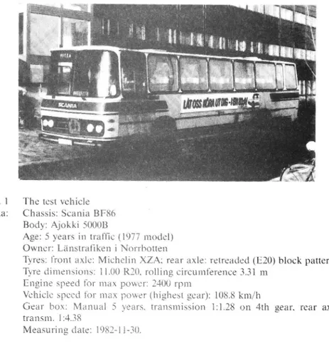
The test vehicle was a Scania BF86 bus with Ajokki SOOOB body (model year 1977). It was chosen for this experiment because it was thought to give higher infrasound than
normal" due to some defect. The bus was constructed with large. plane windows as is
common on modern buses. See Fig. 1. Journal oj'Low Frequency Noise and
INERASOUND GENERATION IN A BUS
Fig. 1 The test vehicle
Data: Chassis: Scania BF86
Body: Ajokki 50008
Age: 5 years in traffic (1977 model) Owner: Länstrafiken i Norrbotten
Tyres: front axle: Michelin XZA; rear axle: retreaded (E20) block pattern
Tyre dimensions: 11.00 R20. rolling circumference 3.31 m
Engine speed for max power: 2400 rpm
Vehicle speed for max power (highest gear): 108.8 km/h
Gear box: Manual 5 years. transmission 1:1.28 on 4th gear, rear axle
transm. 124.38
Measuring date: 1982-11-30. 4. Experimental method
4.1 Measuring system
The measuring system shown in Fig. 2 was used. Due to the wide spectral (2-20000 Hz) as well as amplitude (40-120 dB) ranges. the recordings were divided into two parts;
one comprising 2-1000 Hz and one comprising 20-20000 Hz. The former was recorded
by an FM technique and the latter was recorded directly. The measurements were
made at the driver s seat at a position about 0.1 m to the right of the driver's right ear.
4.2 Analysis system
A real-time frequency analyzer of third-octave band resolution was used, see Fig. 2. Calculations of special weighted overall sound levels were made in the computer.
These included the following weighting curves: Lin No weighting
A. C. D Standardized in IEC 179 and 537
DX As D. but everything below 20 Hz is excluded IL Linear in the range 2-20 Hz. zero outside this range Gl. G2 Standardized in ISO/DIS 7196
I. 11 Special curves constructed to correspond to weighting networks in our infrasound dosimeters"
Marg Margin between the measured spectral levels and the exposure levels (in
third-octave bands) as suggested by Ref. 2. The value given is the level
dif-ference in the third-octave band where the measured value is "worst" in
rela-tion to the exposure levels.
The measuring and analysis time was 128 s (2 min) in each case. This gives a RT
product of 59 at 2 Hz and 590 at 20 Hz which provide adequate precision when
measuring random infrasound signals such as those generated by road unevenness or wind turbulence.
INFRASOUND GENERATION IN A BUS
Measuring system _ | Analysis system
I
Level Printer I _) analyzer IB&K 4426
8&K2312
I
_
I
Cond. micr. I B&K 4163 _ 20-20000 Hz Third-octaveL) Preampli- HP filter Dir Q9 frequency
. ~>> -LigaNagra 20 Hz _ analyzer FM Tape recorder
Nagra IV SJ 8&K 2131 |
I
I
Calibrator I Computer B & K 4220 DataboardI
4680
I
Sound level | meter 2 1000 Hz I Plotter B&K 2209 I Servogor 281 Cond. micr. I B & K 4165I
Fig. 2 The measuring and analysis system. The level analyzer and its printer were
not used in this experiment. The high-pass filter is mounted in the tape recor-der and is used to reduce the risk of overloading the recording due to
high-amplitude low-frequency signals.
4.3 Test roads
The test road was a long straight highway paved with a smooth asphaltic concrete
sur-face (type MABI2T according to the Swedish code). Its unevenness had been
measured by the VTI Laser Road Surface Tester and found to be around 1.2 expressed as IRI in m/km. So. this test road appeared to be quite even.
For comparison one measurement was made on a gravel road with moderate
unevenness. As this was narrow and not straight the speed varied between 40 and 50 km,/h (average 44 km/h). On the IRI scale this road was estimated to have a rating
around 4.5.
4.4 Test runs
The following test runs were made:
30. 50. 70 and 90 km/h on gear No. 5 (No. 4 at 30)
0.4xV. 0.5xV. 0.7xV. 0.7xV. 0.8xV where V is 108.8 km/h (gear No. 5) 0 km/h (idling) with and without fans
Accel. test according to ISO (0.45 0.90xV) on gear No. 5 Accel. test according to SAE (0.5-1.0xV) on gear No. 4
70 km/h on gear No. 5. upwind 2.0 m/s (overall wind speed relfto the bus was
then 21.4 m/s)
Ditto. with windows damped (pushed by the passengers)
70 km/h on gear No. 5. downwind 2.0 m/s (overall wind speed rel. to the bus
was then 17.4 m/s)
Ditto. with windows damped (pushed by the passengers)
Damping of the windows was accomplished by. at a certain moment. the bus passengers pushing their hands rmly on the centre ofthe plane windows (except the curved front windows).
INFRASOUND GENERATION IN A BUS
This could not eliminate window vibrations completely, just reduce them to a lower level. It was estimated that the amplitude could be reduced by about 50% in this way.
5. Hypothetical sources of infrasound in road vehicles
Originally, the following were considered as potential sources of infrasound: ' Vibration in the engine or the transmission
' Vibration caused by road roughness
' Vibration in the body caused by turbulent air flow around the bus ' Air turbulence in open windows ampli ed by a Helmholtz resonator ' Vibration caused by tyre non-uniformity
From earlier, systematic measurements of infrasound spectra in several buses it
was concluded that all buses exhibited essentially the same frequency spectra,
although the levels differed by up to 10 dB between the buses. Therefore it is reason-able to believe that the generation mechanisms are basically the same although of
dif-ferent relative importance. The bus chosen here was found to deviate from the norm
only due to unbalance or run-out of the tyres.
The generation mechanisms have been investigated and reported earlier (Ref. 3). There it was found that all sources listed above, with exception of the first, were
impor-tant, although the two most important were vibration in the body caused by road
roughness and tyre run out/unbalance. '
6. Results
Figs. 3 and 4 show the difference in spectra between driving up- and downwind, i.e. wit slightly different wind turbulence around the bus body. It is evident that the more intense turbulence gives a small increase in infrasound for most frequencies except in
the range 12-20 Hz (the axle resonance); the most exceptional being the frequency of
the highest peak (12.5 Hz ) where the situation is reversed. The increase must be due to turbulence-induced vibration in the body. It may be speculated that the decrease at 12.5 Hz may be due to a higher driving load due to the upwind conditions which may
damp out unbalance in a tyre such as seems to be the case for the rear-axle tyres on this
bus. These tyres were retreaded and by inspection appeared non-uniformly worn. _ 110 T j 7 , ' Y I 1 I l l j 7 ' T T år I I l TI j # 1 T T W T Y I I T
--- UPWIND (WINDOWS UNDAMPED) v DOWNNIND (WINDOWS UNDAMPED)
50 1L i 1l jl'ii Lii il 1 | L iiiii Fiiiii iii
1HZ 2 4 8 16 31.5 53 125 250 500 IKH
7 FREQUENCY
Fig. 3 Spectral changes between driving upwind and downwind (higher and lower
air turbulence. respectively). Windows were undamped.
INFRASOUND GENERATION IN A BUS 0 ,w,,,,,1,1,YT,1jfajjjw,.,,..
[dB] ?
4
WOT 904 J l 80+ 70_tl
i
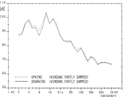
60.T J--- UPWIND (WINDOWS PARTLY DAMPED) ** DOWNWIND (WINDOWS PARTLY DAMPED)
50 ...
"I"I"I"I T"I"I'IITTT'T"
l HZ ? 4 8 16 31.5 63 125 250 500 1K HZ
FREQUENCY
Fig. 4 Spectral changes between driving upwind and downwind (higher and lower
air turbulence, respectively). Windows were partly damped.
110
[dB]
100T J 901. 80_. 704 60'fWINDOWS UNDAMPED (DOWNWIND)
-
--- wmnows PARTLY DAMPED (DOWNWIND)
50 i'Lilil'LllT'L'LI'T'LI'L'LT'L'lirTlli'Lll'Ljn T'L
t HZ 2 4 8 16 31.5 63 125 250 500 lKHZ
FREQUENCY Fig. 5 Spectral changes when the centre ofthe windows were pushed by hand
("par-tly damped") relative to the "undamped" case.
Fig. 5 shows the difference in spectra due to the damping of the windows when
pushing the centre of them. Two effects may be noted:
' The highest peak at 12.5 Hz is reduced by about 5 dB by the "damping ' A new. secondary peak arises at about 4 Hz where the level is increased
by 7 dB ,
The new secondary peak may be due to a lower natural resonance ofthe windows
when its apparent mass is increased several times by the pushing which was intended to da np the vibrations rather than to move the resonance frequency. Ofcourse. the net
effect ofthe "damping" is clearly positive as the overall level is decreased by 2-3 dB on the linear weighting scale and by 3 dB on the newly standardized Gl weighting scale.
INFRASOUND GENERATION IN A BUS
TABLE I
The overall infrasound levels in dB with different weightings. Exc = The maximum excess of the measured spectrum over the exposure spectrum proposed in Ref. 1.
Speed Gear Notes Weighted Sound Levels
km/h Lin IL G1 Exc
70 5 Upwind (undamped windows) 108.7 108.3 114.0 11.8
70 5 Downwind (undamped windows) 110.2 109.9 115.0 10.4
70 5 Average 109.5 109.2 114.5 10.9
70 5 Upwind (damped windows.) 107.4 107.0 111.2 8.6
70 5 Downwind (damped windows) 107.6 107.3 112.1 9.3
70 5 Average 107.5 107.2 111.7 8.9 0 Fans on 87.7 84.0 88.5 15.8 0 Fans off 86.1 82.4 89.2 ~15.0 30 4 103.9 103.7 110.8 7.8 50 5 106.2 105.8 112.3 10.7 70 5 108.8 108.5 113.7 10.7 90 5 110.1 108.6 113.7 10.3 44 3+4 Gravel road 114.1 113.6 120.5 17.4
Table I summarizes the overall levels.
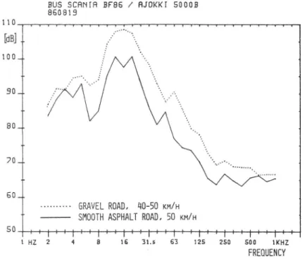
The special test to investigate the effect of road roughness on the infrasound showed that this in uence is important. In Fig. 6 it is clear that for all frequencies 6-200
Hz the infrasound is increased by 5-10 dB. The overall level is increased by 8 dB (G1) despite the speed being a little higher (50 versus average of44 km/h) in the smooth road case. see Table I.
BUS SCRNIFI BFBS / HJOKKI 50008 860819
110
,,,,,,,,,,,,,,,,,,,,,,,,,,,,,,,,
[dB] ..
1oo_.
.
90q. 4so...
70. SD..1 --- GRAVEL ROAD, 40-50 KM/H T SMOOTH ASPHALT ROAD, 50 KM/H50
%%f::f:ff+:i%%i41il'HlfL'il:i:;
1 HZ 2 4 8 15 31.5 63 125 250 500 (H
_
FREQUENCY
Fig. 6 The difference in infrasound when driving on a smooth asphalt road and a rough gravel road.
INFRASOUND GENERATION IN A BUS
Earlier (Ref. 3). it has been shown that tyre run-out~(i.e. the tyre is not circular) and unbalance excites body vibrations and infrasound. In Fig. 7 the very pronounced resonance 12.5 Hz at the speed of70 km/h coincides closely with twice the tyre rotation
frequency (11.7 Hz). It seems that when a multiple of two or three times the tyre
rota-tion frequency comes into the frequency range of axle resonance. then a high peak
may be expected. It was noted in an earlier test programme that the use of retreaded tyres very often resulted in tyre run-out or unbalance with accompanying high infrasound levels. And. of course, to the bus body. roughness in the tyre and the road should have similar effects. Visual inspection showed that the tyre tread on the rear
axle tyres was worn in a non-uniform manner.
The high peak at 31.5 Hz at 90 km/h. which is outside the traditional infrasound range. is likely to be associated with the bus engine frequency which is 33 Hz at this speed (harmonics of two and three times this frequency are also visible).
BUS SCHHIH BF86 / HJOKKI 50008
860819 110 I I I I I I I I I YTT TjW T Yj I I 1 j 1 l Ta TI I I I I l T
[dB] 1
wow '90_L ,. 8th 70 11 1I 50.9 * q)-50 eeftli::itel..]#.f::f ¢4'1 :l'-:.LL.L+ 1 Hz 2 4 a 16 31,5 63 125 250 500 tKHZ FREQUENCY ... 8212 016 0 Kn/H --- 8212-012 30 KH/H, 4 GEHR 8212-013 50 KN/H. 5 GEHR 8212-014 70 KH/H, S GERR ~--- 8212-015 90 KN/H, S GERRFig. 7 The frequency spectra for different driving speeds
7. Conclusions
7.1 Higher air turbulence around the bus appears to slightly increase the level of infrasound at most frequencies outside the range ofthe axle resonance (12-16
Hz). However. the big difference at very low frequencies (2-5 Hz) as reported
in Ref. 3 was not observed for this bus.
By pushing by hand the centres of the plane windows in the bus it was poss-ible to influence the infrasound. The overall infrasound level was decreased by 3 dB (Gl-weighted) by this simple activity. However. it seemed that the result was caused mainly by a removal of the window resonance to a lower and less sensitive frequency. rather than by really damping" the vibrations. Both effects could of course be present. This clearly demonstrates that infrasound may be easily abated by changing the window resonances. Road roughness or unevenness has a pronounced influence on infrasound generation. It means that the roughness excites axle vibrations which are
transmitted to the body and radiated from the large panels in the bus as
infrasound.
INFRASOUND GENERATION IN A BUS
7.4 Similarly, "roughness in the tyres (unbalance or run-out), which especially seems to be associated with retreaded tyres, may excite vibration and
infrasound.
8. Recommendations
When abating infrasound in buses, efforts should be made to separate the axle or
sus-pension resonance, window natural frequencies, tyre unbalance or run-out frequen- . cies (especially their harmonics), engine rotation frequency and the cabin air
resonance mode (halfthe wavelength equals the cabin length). In certain circumstan-ces all these may coincide to give high infrasound levels. Since human perception is more sensitive to the higher infrasound frequencies, it is preferable to shift the
resonances to lower frequencies, if possible.
A first, quite simple step, would be to increase the damping and/or change the
natural frequencies ofthe large windows in the bus. Another effective step would be to check non-original tyres for run-out or unbalance.
References
]. Sandberg, U. Combined Effect ofNoise, Infrasound and Vibration on Driver
Per-formance. Proceedings of Inter-Noise 83 in Edinburgh, pp 88 7-890 (Also reprint No. 86, Swedish Road and Traffic Research Institute).
2. Arbetarskyddsstyrelsens kungörelse med föreskrifter om buller (requirements regarding noise). AFS 198o:l5, The National Board of Occupational Safety and Health, Stockho/m, 1986-08-20.
Sandberg, U.: The Generation ofInfrasound in Buses. Proceedings ofInter-Noise 81 in Amsterdam, pp 727-732. (Also reprint No. 65. Swedish Road and Traf c
Research Institute).
U.
)