DEGREE PROJECT IN MECHANICAL ENGINEERING, INNOVATION AND DESIGN, FIRST CYCLE, 15 CREDITS SÖDERTÄLJE, SWEDEN 2019
BTPX 305 Separator
Vibration damper of the vertical drive
SADOR ALEMSEGED
NOORALDEEN SALEEM
SCHOOL OF INDUSTRIAL ENGINEERING AND MANAGEMENT
DEPARTMENT OF SUSTAINABLE PRODUCTION DEVELOPMENT
BTPX 305 Separator
Sador AlemsegedNooraldeen Saleem
Degree project TRITA-ITM-EX 2019:405 KTH Industrial engineering and management Mechanical engineering, Innovation, and design
III
Degree project TRITA-ITM-EX 2019:405 BTPX 305 separator Sador Alemseged Nooraldeen Saleem Approved 2019-06-10 Examiner KTH Mark Lange Supervisor KTH Mark Lange Commissioner
Alfa Laval Tumba AB
Contact person at company Ola Curtius
Abstract
This thesis analyzes BTPX 305, a biotech separator developed by Alfa Laval. It focuses on a problem found in the vertical drive where the machine's vibration absorber and damper take place. Today the machine is experiencing vibration above the normal levels, and the product that the machine usually separates is very sensitive to vibration. Therefore, the damping mechanism in the machine needs to be serviced often because of wear in the damping mechanism. In the report, a variety of methods are used, TIPS (the Theory of Inventive Problem Solving) for example are used to model and describe the problem in more detail, and internal/external research is done to possibly find inspiration from other machines that have solutions to similar problems. Solution ideas were generated in brainstorming sessions that were mostly inspired by the information gathered from both the internal and external sources. The concepts were then adapted to then become a solution proposal to the problem. With the help of a priority matrix, it was decided which of the concepts should be considered reasonable as a solution proposal. A couple of experiments were conducted on the concepts that were further taken from the priority matrix to ensure that the theory works in practice.
IV
Examensarbete TRITA-ITM-EX 2019:405 BTPX 305 separator Sador Alemseged Nooraldeen Saleem Godkänt 2019-06-10 Examinator KTH Mark W.Lange Handledare KTH Mark W.Lange UppdragsgivareAlfa Laval Tumba AB
Företagskontakt/handledare Ola Curtius
Sammanfattning
Projektet analyserar BTPX 305, en biotechseparator utvecklad av Alfa Laval. Arbetet fokuserar på ett problem som finns i den vertikala enheten där maskinens vibrationsdämpare äger rum. Idag upplever maskinen en vibration över normala nivåer. Produkterna som maskinen brukar separera är mycket känslig för vibrationer och därför måste maskinen ofta kontrolleras på grund av slitage i dämpningsmekanismen. I rapporten används olika metoder, till exempel används TIPS (the Theory of Inventive Problem Solving) för att modellera och beskriva problemet mer detaljerat och en intern/extern forskning görs för att eventuellt hitta inspiration från andra maskiner som har lösningar för liknande problem. Lösningsidéer genererades i brainstorming sessioner som inspirerades av den informationen som samlats in från både interna och externa källor. Koncepterna anpassades sedan för att bli möjliga lösningsförslag till problemet. Med hjälp av en prioriteringsmatris bestämdes vilka av lösningsförslagen som skulle anses vara rimliga att arbeta vidare med. Ett par experiment gjordes på de koncepten som togs vidare från prioritetsmatrisen för att säkerställa att teorin fungerar i praktiken.
V
Acknowledgment
Firstly, we would like to thank our supervisor and examiner Mark W.Lange at KTH. Who has given us great input on how to create a thesis of high quality.
We would also like to thank Alfa Laval for the opportunity to work in their offices and for getting us inspired to work hard. Special thanks to our supervisor at Alfa Laval, Ola Curtius, for all his support and guidance throughout the thesis project.
Contents
1 Introduction ... 1 1.1 Background ... 1 1.2 Problem statement ... 2 1.3 Goal ... 2 1.4 Purpose ... 2 1.5 Delimitations ... 2 1.6 Solution methods ... 2 1.6.1 Internal sources ... 3 1.6.2 External sources ... 3 1.6.3 Other methods ... 3 2 Research ... 52.1 Basic principles of an industrial separator... 5
2.1.1 Gravity separation ... 5
2.1.2 Heat separation ... 6
2.1.3 Centrifugal separation ... 6
2.2 Design and function overview of a basic Alfa Laval’s separator ... 7
2.2.1 Machine top ... 7
2.2.2 Machine bottom ... 7
2.2.3 Designation of Alfa Laval’s machines ... 7
2.3 BTPX 305 properties ... 8
2.4 Design and function overview of BTPX 305 ... 9
2.5 The main parts and functions of the vertical driving device ...10
2.5.1 Vibration dampening mechanism of BTPX 305 ...10
2.5.2 Balancing mechanism ... 11
2.6 The theory of inventive problem solving (TIPS) ... 12
2.7 Damping mechanism in other Alfa Laval’s machines ... 13
2.8 Summary of the internal research ... 14
2.9 External sources ... 15
2.9.1 Airless tire ... 15
2.9.2 Compliant mechanism ... 17
2.9.3 Leaf springs ... 17
2.9.4 Magnetic Ride Control (MRC or MagneRide) ... 18
2.9.5 Eddy current ... 19
3 Implementation ... 21
3.1 Improvement of the current solution ... 21
3.1.1 Concept 1 “Diamond” ... 21
3.1.2 Concept 2 “Rubber and bushing”. ... 23
3.2.1 Concept 3 “IRIS” ... 24
3.2.2 Concept 4 “Wheel” ... 25
3.3 Concept 5 “Leaf” ... 26
3.4 Application of magnetic principles ... 26
3.4.1 Concept 6 “Eddy’s current” ... 26
3.4.2 Concept 7 “MagneRide” ... 26
3.5 Prioritizing matrix ... 27
4 Results ... 29
4.1 Bushing and rubber ... 29
4.2 IRIS ... 30 4.3 MagneRide ... 31 4.4 Eddy current ... 32 5 Discussion ... 33 6 Conclusion ... 35 References ... 37
Chapter 1
1
Introduction
This chapter will introduce the reader to the background of both Alfa Laval and the machine that this thesis will be focused on. Then a problem statement will follow, that builds up to the goal, purpose, delimitations, and the solutions methods that will be presented in this thesis.
1.1 Background
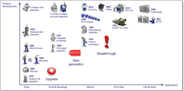
In 1879 the first continuous separator was demonstrated in Stockholm. Then in 1883 Gustav De Laval and his partner, Oscar Lamm, established the company AB Separator which changed its name to Alfa-Laval in 1963. Today Alfa Alfa-Laval has a wide range of products. The key ones are heat exchangers, separators, pumps, and valves.
Alfa Laval’s worldwide organization helps customers in nearly 100 countries to optimize their processes. The company has over 17 000 employees, the majority of whom are in Sweden, Denmark, India, China, the US, and France. The company started with cream separators, wherein 1898; the company started a business unit for Food & Beverage. In the same year, the first yeast separator was installed in a customer’s production line. In 1916 it began selling separators for oil purification. Also, in 1983 Alfa Laval introduced its first biotech separator the BTPX. The biotech separator is used to separate sensitive products. It is very important to keep the separator clean and use materials that don’t contaminate the product, which is why this separator has gone through a lot of development as it is now in its 3rd generation
(BTPX 305). BTPX 305 is an outstanding biotech separator system for biotechnology and the pharmaceutical industry.
1.2 Problem statement
The problem is that the BTPX 305 is experiencing vibrations above the normal levels; this occurs exclusively when the machines operating speed reaches above 8500 RPM. Vibrations are expected since many factors lead to an imbalance in the machine. Alfa Laval admits that they can’t stop the vibrations, but there should be at least a dampening mechanism that reduces the vibration to a safe level. Over the limit vibrations are harmful and can damage the product being separated. The current dampening mechanism relays on friction, which wears out the components in the dampening mechanism. The worn components need to be serviced, which happens frequently. Therefore, this thesis will focus on developing an alternative dampening mechanism for the BTPX 305.
1.3 Goal
The project goal is to develop a solution proposal that mends the current problem. That is, to develop a damping mechanism that can handle the forces and frequencies that emerge during operation with less wear rate.
1.4 Purpose
The project aims to study the vertical drive of BTPX 305 and its damping mechanism to identify the cause of the problem. Based on that information and research about damping mechanism in other machines, a solution proposal should be developed, which will enable technologists to demonstrate their aptitudes as engineers and problem solvers.
1.5 Delimitations
Some delimitations are needed to meet the established goal within the time frame of ten weeks. One of the most crucial customer requirements is that the solution proposal to be developed should not exceed the physical volume used by the vertical drive’s damping mechanism found in the present product design. A 3D CAD model will be used to illustrate the solution proposal; however, the tolerance of the model is not to be defined or considered.
The imbalance that occurs in the bowl for various reasons will not be included in the study since it does not serve any purpose in solving the problem.
1.6 Solution methods
The solution methods that were performed to gather information and generate ideas for the solution proposal can be categorized into three main sections. Those methods are internal sources, external sources, and other methods. The internal source covers all the information that was gathered with the direct help of Alfa Laval’s resources. The external sources cover the researches that were made outside of Alfa Laval’s facility, such as “Internet search”. While the other methods cover the main tools that were helpful in this project.
1.6.1 Internal sources
To understand and solve the problem, a brief knowledge of the machine (BTPX 305) is needed. In this case, Alfa Laval didn’t have any type of documentation that describes the machine and the functions of its components. Therefore, an internal search, which focuses on the machine and its components was implemented. This research was done with the help of Alfa Laval’s database (Sensei PDM & Creo), which contains drawings of the machines and their components. By studying the drawings, the function and design of the components could be identified and described. The functions which could not be identified by observing the drawings were identified by implementing an interview of Alfa Laval’s employees (Engineers) who had a lot of experience with BTPX 305 and other similar separation products. The engineers who were interviewed are Ola Curtius (Design leader), Martin Hansson (Development engineer, machine dynamics) and Aksel Kristensen (Test engineer).
The database was even helpful in the research of the damping mechanism in other Alfa Laval’s machines. And extensive search was implemented to see if there was any other damping mechanism, which we could implement in this solution proposal.
1.6.2 External sources
To be able to develop a mechanism that could be used as a solution concept in the current problem, further knowledge about the existing solution principle was needed. This knowledge could be gained with the help of external sources, such as searching on the internet. This research covers other damping mechanisms that are currently used in other aspects or mechanisms outside the domain and experience of Alfa Laval that have potential to solve the problem.
1.6.3 Other methods
Other methods, such as “the Theory of Inventive Problem Solving (TIPS)” was used to model and describe the problem further. This method was useful in understanding how the different component affects each other and then find out precisely where the problem is. The information that was gained from the TIPS, internal and external sources were utilized with the help of brainstorm. Brainstorming was one of the main tools that were commonly used in producing possible solutions. Those solutions were modeled in 3D with the help of CREO Parametric. Prototypes for demonstrations and experiments were made with the help of a 3D printer. At last, a prioritizing matrix was implemented to compare the proposal concepts and recommend the most appropriate for further study.
Chapter 2
2
Research
This chapter will introduce the reader to the basics of separation and information about the machine that this thesis is studying. Furthermore, a detailed explanation about precisely what and where the problem is located. This will be presented with the help of interviews and using the TIPS tool to analyze the relationship between the components in the dampening mechanism. After that, a summary of all the machines that were studied and external sources that could have the potential to lead towards a solutions proposal.
2.1 Basic principles of an industrial separator
A separator is a machine or device that separates something into its constituent or distinct elements (Alfa Laval Tumba, 2018).
The purpose of separation can be:
• To free a liquid from solid particles
• To separate two mutually insoluble liquids with different densities while removing any solids presents at the same time
• To separate and concentrate solid particles from a liquid
There are three main basic methods of separation principles that are applied to a separator to realize the separation process; those are gravity, heat, and centrifugal separations (Alfa Laval Tumba, 2018).
2.1.1 Gravity separation
The first and absolutely the most basic method is gravity separation, which is a common industrial method that separates two components with different density using the gravity force. In this process, a lighter liquid rises while a denser liquid or solid will sink to the bottom because of the gravity force. The result will be that the heavier particles will build a sediment layer in the bottom, which make it very easy to separate from the rest. The advantage of this method is that it is cheap, but it is a slow process which makes it ineffective from an industrial perspective (Alfa Laval Tumba, 2018).
2.1.2 Heat separation
Separation by temperature is among the common separation method that takes advantage of thermal energy to influence the density and viscosity of the product, where the viscosity and density of a product will reduce if heat is implemented. Lower viscosity and density will make the product easier to separate. Therefore, separation by temperature is used to increase the separation capacity. However, the temperature should be kept constant for the best result. Figure 2.2 illustrates the viscosity of material with and without implementing a temperature (Alfa Laval Tumba, 2018).
2.1.3 Centrifugal separation
Centrifugal separation is the common and most complex separation method in the industrial separation world. Unlike gravity separation, this process continues. The main principle of this process is to apply a centrifugal force to simulate gravity. By rotating the bowl (which contains the product to be separated) with a certain speed, the product will be separated according to their size, density, viscosity, etc. This process replaces the force of gravity by centrifugal force, and this leads to a way faster separation than the other processes. This process can even be influenced by a lot of other factors like rotation speed, temperature, etc. for example the higher rotation speeds, the faster the separation process will be (Alfa Laval Tumba, 2018).
6 | CHAPTER 2. RESEARCH
Figure 2.1: Schematic of a gravity separation.
Figure 2.2: The viscosity of a material changes when heat is applied (B), allowing the material to more easily flow compared to the container (A).
Figure 2.3: Illustration of a centrifugal separation. Lighter liquid(A), Heavier liquid(B) and the Centrifugal force(C).
2.2 Design and function overview of a basic Alfa Laval’s separator
Alfa Laval separators use the centrifugal separation method, and that is why the machines are very complex and consist of many components. However, the main parts of the machines can be categorized into two groups the “Machine top” and “Machine bottom.”
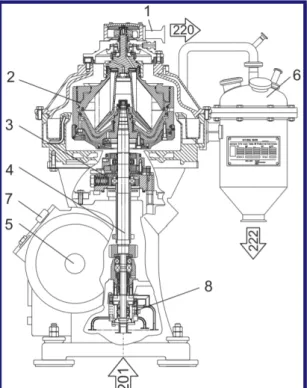
2.2.1 Machine top
The upper part of a separator contains the processing parts, the bowl (2) and the outlet device (1). In the bowl, the liquid is separated from the heavier sediment. The bowl contains the discharge mechanism which empties sediment from the bowl (Alfa Laval Tumba, 2018).
2.2.2 Machine bottom
The bottom part of the separator contains a motor and a worm gear that makes the bowl spindle rotate at high speed. The bowl spindle (4) is hollow, and its lower end is connected to the liquid inlet (201). The spindle is a part of the vertical drive, which controls and transmits the rotation from the motor to the bowl (Alfa Laval Tumba, 2018).
2.2.3 Designation of Alfa Laval’s machines
In order to identify the properties and similarity of separators among the hundreds of Alfa Laval machines, the separators have been given specific designation (name codes). This is useful to understand the type and function of the separation machine. For example, the machine that is going to be studied in this project is BTPX 305, and that designation stands for as follows:
*Biotech is a process of developing or making products from organisms or living systems; it is very sensitive taken the consideration that small defects can contaminate the final product.
**Side shooting is when the machine has an opening on the bowl sides in order to eject the unwanted product.
Figure 2.4: Overview of Alfa Laval´s separator. CHAPTER 2. RESEARCH | 7
B T P X
3 0 5
2.3 BTPX 305 properties
This machine is an outstanding separator system for biotechnology and the pharmaceutical industry. According to the technical data the machine is designed to handle very high-speed separation and should manage to operate with a speed up to 9 650 rpm without any problems. As Figure 2.5aillustrates, the complete system is a quite large machine with a lot of complex components connected and influences each other (Alfa Laval Tumba, 2018).
Because the BTPX has a high-performance specification, its mass and operation speed make it very sensitive to vibration. Over the limit vibrations can cause various types of damage to both the product and the machine itself. To prevent this there is a vibration sensor that gives a signal as a warning when it is critical, and then it gives a second signal that shuts the machine down to prevent further damage to the machine's components (Alfa Laval Tumba, 2018).
8 | CHAPTER 2. RESEARCH
Figure 2.5a: Overalll dimentions of the BTPX 305.
Figure 2.5b: BTPX 305 properties and technical data. BTPX 305
2.4 Design and function overview of BTPX 305
BTPX 305 is an old small machine compared to the other machines with similar function in Alfa Laval. This means the design of the machine can be a bit complex in order to fit all the components in such a small space. The machine top (see Figure 2.6) is where the product is separated and ejected. In this region of the machine, there are components like the separator bowl, outlet seal, etc. The primary separation process occurs in this part of the machine, and by connecting necessary components, it is easier to manage the retention process of the final product and its waste which shoots out from the side (Alfa Laval Tumba, 2018).
The machine top is then connected to the machine bottom, which helps it to rotate. The machine bottom is where the product to be separated is injected and, in this section, is where both the vertical and the horizontal driving device is located. The horizontal driving device consists of a worm gear in order to transmit the rotational force from the motor and transmits it further to the machine top with the help of the vertical drive.
The vertical drive contains all the stabilization and dampening mechanism, and the main component that connects the main motor to the bowl, which is the spindle. The spindle has many functions in its delivery of the product into the bowl. Delivering the product through the spindle makes sure that the product effectively goes through the bowl to be separated. The spindle is the only part that transfers the rotational force from the horizontal drive to the bowl. The spindles hidden function is that its itself is a spring that dampens some of the vibrations and the forces produced by the bowl (Alfa Laval Tumba, 2018).
Figure 2.6: Drawing of the top machine section.
CHAPTER 2. RESEARCH | 9
A
B
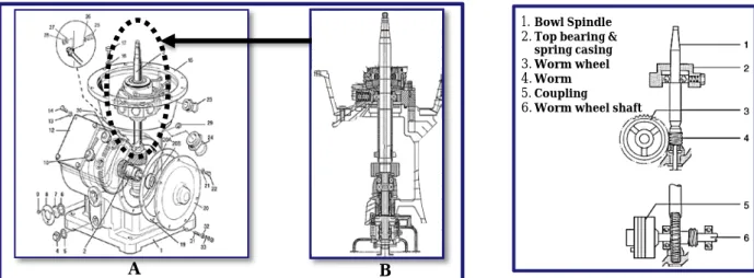
1.Bowl Spindle 2.Top bearing &
spring casing 3.Worm wheel 4.Worm 5.Coupling 6.Worm wheel shaft
Figure 2.7b: The arrangement of the vertical drive’s components.
Figure 2.7a: Drawing of the bottom machine, where A is a complete assembly drawing and B is a drawing of the vertical drive.
2.5 The main parts and functions of the vertical driving device
As it is discussed in the Section, 2.1.3 speed is one of the essential factors in the centrifugal separation process. When providing a high level of speed, the machine generates a lot of force, which can cause unwanted vibrations and imbalance in the machine. Therefore, the bowl and the vertical drive that transmits the force should be well balanced to prevent vibrations and imbalance. consequently, the vertical drive in this machine should be well balanced and even have some damping mechanism for the vibrations.
2.5.1 Vibration dampening mechanism of BTPX 305
The vibration dampening mechanism in the BTPX 305 consists of nine springs and buffers (Radial buffer & Screw plug) assembled in a round housing, as it is shown at the left top corner of Figure 2.8. The buffers are two halves hollow cylinders so that they can contain and hold the spring in position. The springs are placed inside the buffers, and by leaving a small space between the buffers, the flexible ability of the mechanism can be gained, this can be seen in Figure 2.8.
When a vibrational force is applied, the radial buffer will be pushed outwards, which then compress the spring. When the applied force is released, the spring stretches back and push back the radial buffer into its primary position. The movement of the buffer creates friction between the buffer itself and the housing wall, and this helps to dampen the vibration.
The issue with this mechanism is that the radial bushing overheats and wears out earlier than the intended design life. When the bushing wears out, the gap between the bushing and bearing housing becomes large, which leads to misalignment of the bushing. If the bushing is misaligned, the damping mechanism will fail. This issue is currently common when the machine’s operating speed exceeds around 8500 RPM (Kristensen, 2019) . 10 | CHAPTER 2. RESEARCH
F
Vertical drive Ball bearing Radial buffer Compression spring O-ring Screw plug Friction surface Spring housingFigure 2.8: Schamatic of the bearing housing’s assembly and some of the components within the mechanism.
2.5.2 Balancing mechanism
At present, the machine is equipped with two basic balancing mechanisms. The first one is based on tow different types of bearing packaging. The first bearing package is mounted at the top in order to support the vertical driving device in the horizontal direction. While the second bearing package is mounted at the bottom to support and carries the vertical driving device in the vertical direction.
The second balancing mechanism uses the basic flexibility theory in the spindle. The spindle is designed to be flexible during the operation, which means that the spindle has the ability to bend while rotating. This feature is useful when an imbalance of the bowl arises due to different factors; some of the causes could be an uneven distribution of the product or mucus in the bowl. Imbalance appears when the bowl does not have the same center of gravity as the spindle. That is why the spindle is constructed with a tolerance to bend approximately 0.2 mm so that it can handle some imbalance moments, which is considered as “acceptable imbalance.” However, over the limit imbalance “unacceptable imbalance” in the bowl causes uncontrolled bending “banana shape bending” of the spindle, and that leads to over limit vibrations (Hansson, 2019). CHAPTER 2. RESEARCH | 11 Top bearing. Support in the horizontal direction Bottom bearing. Support in the Vertical direction
Figure 2.9: Bearings that are mounted in the vertical drive.
Figure 2.10a: Perfect balanced bowl.
Figure 2.10b: Acceptable imbalance of the bowl. Figure 2.10c: Unacceptable imbalance of the bowl.
2.6 The Theory of Inventive Problem Solving (TIPS)
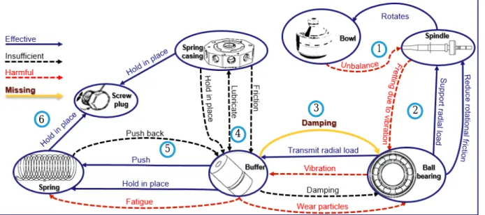
The theory of inventive problem solving (TIPS) was used to identify the problem further. This method has a modeling tool that is used to identify and describe the relationship between the objects (i.e., components) in an assembly or a system. As Figure 2.11shows with the help of arrows that vary in shape and color, the tool demonstrates the relationship between the component. This helps identify which component is the most effective and which is the most harmful to its self or other components.
1. The relationship between the bowl and spindle is simple. The spindle transforms the rotational force from the horizontal drive to the bowl. Because of imperfections in the bowl, it’s usually not perfectly balanced, which means that the spindle is not perfectly balanced either.
2. The ball bearing is there to reduce the rotational friction and support the radial loads that occur when the spindle begins to vibrate because of unbalancing. That results in fretting wear* which over a period of time will remove material from one or both surfaces in contact.
3. This mechanism depends on friction for dampening. A buffer is used to take on the radial load from the ball bearing and dampen the vibrations. This procedure can cause some wear particles to move into the system and maybe cause damage. There is a chance that the particles are entering the ball bearing and causing erosive wear**.
4. The spring casing is a vital component that holds the dampening components together against the spindle. The casing has tubes built in it to guide lubricant to the dampening mechanisms. The buffer uses the casing as a friction surface to dampen the vibrations.
5. The spring is used to help the buffer dampen the vibrations by pushing the buffer back to its original position after a pulse of vibration. The spring material is weakened by cyclic loading, which causes a form of fatigue that causes an eventual failure of the spring.
6. The screw plug is a component that both compresses the spring into a working level and holds it in place with the help of threads in the spring casing.
12 | CHAPTER 2. RESEARCH 5 4 3 2 1 6
Figure 2.11: TIPS function model over BTPX 305’s current vibration damping mechanism.
* Fretting wear refers to corrosion damage between contact surfaces. This damage is induced under load and in the presence of repeated relative surface motion.
2.7 Damping mechanism in other Alfa Laval’s machines
Alfa Laval has more than 125 years of practical experience of High-Speed Separators and has a lot of separators that don’t have a similar issue with vibration as BTPX 305. Therefore, it was essential to examine how the other machines damping mechanism works and see if these alternative solutions can be implemented in BTPX 305. After investigating around 250 different machines, there were some interesting mechanisms showed up that have the potential to solve the BTPX 305 problem.
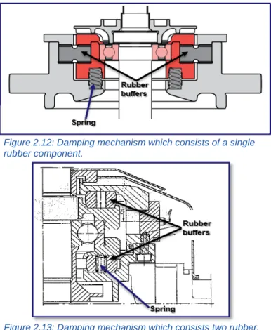
The first one is a mechanism that dampens the vibration in the horizontal direction with the help of circular rubber buffer and at the same time support and carries the vertical driving device with the help of spring. This rubber is placed around the top bearing while the springs are placed under the top bearing in the horizontal direction, see Figure 2.12 as it shows the drawing of the mechanism. The second machine’s mechanism consists of two large circular rubbers with a spring inside them, which is placed around the top bearing. This mechanism can be seen in Figure 2.13, which shows the layout of the mechanism.
But after an interview with Martin Hansson (Development engineer, machine dynamics) it was clear that rubber buffer is a better dampener than a spring, but if the rubber is exposed to a high compression force, it can easily be crushed. The biggest issue here is that these two machines have a lower operating speed, which means this rubber is exposed to a lower vibration comparing to the BTPX 305. Rubber is very sensitive that sometimes it gets damaged during assembly. Therefore, none of those mechanisms can be applied to BTPX 305 without modification and further research (Hansson, 2019).
CHAPTER 2. RESEARCH | 13
Figure 2.12: Damping mechanism which consists of a single rubber component.
2.8 Summary of the internal research
According to the facts from interviews with Alfa Lava’s employees, researches in Alfa Lava’s database and TIPS, the following conclusion could be made.
• It is tough to make the bowl perfectly balanced with that many components and high speed. • Rubber buffer is better dampener than spring, but if they are exposed to a higher vibration force,
they can easily be crushed.
• The vibration issue is common in the high-speed separators taking into consideration the BTPX’s operating speed, and the products which are separated in this machine makes BTPX sensitive to over limit vibration.
• When the machine is operating at very high speed, the lubricant starts to boil, and after all the volatile elements have been boiled out of the lubricant, it will solidify, which then makes the lubricant ineffective.
• When the lubricate solidifies the bushing overheats and wears out earlier than the intended design life, and this leads misalignment of the bushing.
• If the bushing is misaligned the damping mechanism will fail, this happens because the springs are going to be squashed and this makes them unable to push back the bushing to its correct position.
• The damping capacity of the BTPX’s vibration damping mechanism fails when the machine reaches an operating speed around 8500 RPM and above.
• The problem could be solved using a damping mechanism that is stiffer but still has an elastic ability, which are tow functional properties currently in conflict with each other.
2.9 External sources
In order to improve knowledge in this project field, external sources were investigated and studied. This includes what kind of mechanism is used to dampen vibrations and even how to implement elastic elements or make the mechanism flexible. The research was productive but still needs out of the box thoughts and changes in order to realize both the elastics and damping ability.
2.9.1 Airless tire
Airless tires have been developed by many companies, but Michelin announced the first idea in 2005. The airless tire principle is simple, to take advantage of materials with high elastic deformation. The materials that are in use, in this case, are compressed polymers which have properties such as low density, flexibility, resistance to fatigue and oil (Lazonby, 2017).
The airless tires can have different appearances, but all work in the same basic principle; a simple example of such tire can look like as Figure 2.14 shows. The spokes of the tire are made of polymers so that the spokes deform temporarily at need (force is applied) and gain its original shape rapidly after the force is removed (Grabianowaski, 2007). As the spoken bends the tread and shear bands deform temporarily as well, then quickly spring back into shape when the force is released. By changing the shape and tensions of the spoke, different characteristics can be gained. This principle has the ability to dampen vibration and flexibility (see Figure 2.16), which can
be used in this project. However, according to the results after testing those tires vibrate significantly on rough surfaces and even produce a lot of heat and noise when the speed is above 50 mph (Grabianowaski, 2007). This is maybe a negative side of the mechanism, but in this project, the vibration of the spindle is not as rough as the vibration the tire experience on the road, which makes it a minor problem. This principle is flexible in only one direction, and this could prevent it from using it in this project, considering the spindle needs to be flexible in two directions, both vertical and horizontal.
CHAPTER 2. RESEARCH | 15
Figure 2.14: “Tweel” airless tire’s components (Grabianowaski, 2007).
Figure 2.16: Airless tires with different designs of spokes and characteristics (Grabianowaski, 2007).
Figure 2.15: An example of airless tire (Grabianowaski, 2007).
There are other types of airless tires such as “superplastic tire” which is invented by Nasa Glenn research center which has the same characteristic as the tires above. This tire goes back to its original shape after having undergoing deformation. This invention was possible thanks to a shape memory alloy, which are materials that can be stretched and reshaped by applying heat. In this case, the material they used is a nickel-titanium wire mesh. (Aguilar, 2017). Figure 2.17 illustrates both “superplastic tire” and shape memory alloy.
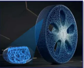
Michelin has a concept of a 3D printed airless tire. Using a honey cone pattern and some inspiration from nature and made of organic materials. The airless tire has a better dampening capability than a typical rubber tire, and it lasts much longer (Hawkins, 2017). Figure 2.18 illustrated 3D printed airless tire.
The disadvantage of “superplastic tire” & “3D printed airless tire” is that those haven't been tested long enough to ensure they will fulfill the theory behind them. That makes it risky and expensive to apply those principles in this project, but those principles look promising in the future and can solve the current problem easily.
16 | CHAPTER 2. RESEARCH
Figure 2.17a: Testing the prototype of “Superplastic tire” (Aguilar, 2017).
Figure 2.17b: An example of the shape memory allay (Aguilar, 2017).
2.9.2 Compliant mechanism
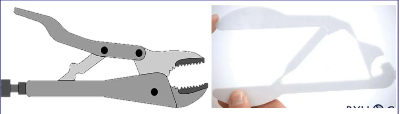
It has always been considered bad to have flexibility in a machine, but compliant mechanisms use flexibility to an advantage (Veritasium, 2019). A compliant mechanism is a mechanism that gains at least some of its mobility from flexible parts instead of joints. Mostly it is the design that decides where in the part that should be flexible and where it should not by varying the amount of material in corners or cross-sections. The vise grip is one of many things that can be manufactured using a compliant mechanism.
This technique has the advantage of a dramatic reduction in the total number of parts required to accomplish a specified task. The reduction in part count results in a smaller number of movable joints, such as pin and sliding joints. This also results in reduced friction and the need for lubrication.
Since compliant mechanisms rely on the deflection of flexible members, energy is stored in the form of strain energy in the flexible members. This can be used as a spring or as a damping mechanism (Howell, 2019).
2.9.3 Leaf springs
Leaf springs are commonly used in motor vehicles like trucks and cars, where the leaf’s stiffness adapts to the magnitude of the force applied. These types of springs were used in cars before the shock absorber was invented. They provided absorption and dampening of bumps and vibrations. Of course, they are not as good as a coil spring and a shock, but they are simpler and cheaper to manufacture (Lyons, 2017).
CHAPTER 2. RESEARCH | 17
Figure 2.19: A good example of a compliant mechanism used to reduce the number of joints (Howell, 2019).
Figure 2.20: An example of a standard leaf spring of a type found in a motor vehicle (Lyons, 2017).
2.9.4 Magnetic Ride Control (MRC or MagneRide)
GM Authority defines this technology as followed “Magnetic Ride Control (MRC or MagneRide) as a General Motors chassis and suspension technology that adapts and adjusts the shock absorbers of a vehicle in real-time in response to changes in terrain in order to deliver optimal shock damping for the best possible driving experience” (Szymkowski, 2019). In order to understand how MRC works, an understanding of the hydraulic dampening is needed, which is the most common shock absorber and damping mechanism in cars. A typical hydraulic damping system illustrates in Figure 2.21.
When a force is applied on the upper mount, the piston rod is forced to move towards the lower mount, and at this moment, the fluid (oil) in the piston is forced to move in the opposite direction through the piston head openings. This will give the absorber the ability to damp the applied force and at the same time, be flexible. The movement of the damper can determine by the viscosity of the fluid in the cylinder and the size of piston head openings. The smaller the openings are, the difficult it is for the oil to pass through the openings, and this makes the damper stiffer (Smith, 2018). In order to make it flexible, the damper is equipped with a spring. This will help the piston rod to move to its extended position when the applied force is sufficiently dampened.
Magnetic Ride Control has the same principle as hydraulic dampening but applies a magnetic field together with tiny iron microspheres into the hydraulic damper. The cylinder is containing fluid, two pair of electromagnetic coils and two small fluid passages through the piston. In this case, the fluid contains the tiny iron microspheres so that when a magnetic field is applied to the coils, the fluid increases its viscosity. When the magnets are OFF the fluid travels through the passages freely but when they are ON the iron particles in the fluid create a fibrous structure through the passages in the same direction of the magnetic see Figure 2.22. This makes the movement slower and influences the viscosity of the fluid. Thanks to this action, the viscosity can be controlled by changing the strength of the current, with the help
Figure 2.21: Illustration of the typical hydraulic damping system (Smith, 2018). 18 | CHAPTER 2. RESEARCH
of a sensor the damper can change its stiffness depending on the situation (Smith, 2018). Figure 2.23 illustrates how MRC damper looks like.
2.9.5 Eddy current
When a conductor moves in a magnetic field or when a magnetic field moves relative to a conductor, then a current loop occurs in the conductor, which is referred to as eddy current. Because the current loop is a reaction to the magnetic field, the loop will produce its own magnetic field to counter the existing one. This will create a significant drag, called magnetic damping.
Figure 2.24 shows how an experiment is conducted by fastening a plate made of aluminum at the end of a rod. The rod is hanged like a pendulum. When the plate is released from a certain Height, the plates brakes and eventually comes to a rest. The plate reacts to both the direction of the magnetic field and the position of the plate. These decide the reacting loop direction. The speed of the plate and the strength of the magnetic field decide the magnitude of the dampening. All these variables can be changed depending on the task (Lumen, 2018).
CHAPTER 2. RESEARCH | 19
Figure 2.23: A complete MRC shock absorber (Smith, 2018).
Figure 2.22b: Whenthe magnets are ON (Smith, 2018).
Figure 2.22a: Whenthe magnets are OFF (Smith, 2018).
Figure 2.24: Illustration of how an aluminum plate react to a magnetic field (Lumen, 2018).
Chapter 3
3
Implementation
This chapter will introduce the reader to the ideas that will shape the result of the project. These ideas have been generated with the help of a couple of methods such as brainstorming and external/internal sources. At the end of this chapter, there will be a matrix that shows which concepts or ideas are more worth continuing to work on and which are not.
3.1 Improvement of the current solution
In order to solve the problem, it is obvious to start with some ideas to develop the current solution so that It may achieve app the specifications required to solve the problem. With the help of studies of the machine and with some inspiration of external sources it was easier to come up with something that is not that much different from the current solution but still is different enough to overcome the problems that the machine has today.
3.1.1 Concept 1 “Diamond”
This concept´s main idea is to increase the friction surface in the interface between the components in order to increase the life of components. In the current solution, the bushings are not connected to the center circle at all times, and this leads to the force applies only in one of the bushings at time. This means the bushing is subjected to large forces, and this leads to an excessive wearing. To prevent this from happening in this concept, the dampen mechanism’s components are connected to each other in order to share the force.
Figure 3.1: Illustration of “Diamond concept”.
Springs Joint Bearing housing
Metal plate
Outer body
The concept consists of eight diamond-shaped damping mechanism which uses the friction damping principle. Each “Diamond” has four metal plate which crosses intersections each other and joins with the help of four joints. There will be even two spring, one horizontal and the other one vertical in order to make it dampen. All those components should be attached to the bearing housing and outer body with the help of clevis, which makes the diamond flexible in all direction.
Figure 3.2 shows an example of how the diamonds help each and share the force in order to dampen the applied force or in this case, the vibrations. When the force (F) is applied the vertical spring of A, and horizontal spring of B will be compressed while the other springs stretch, this will make the mechanism stiffer and elastic at the same time. Thanks to the joining of diamonds, the force will be shared between the “eight diamonds”, this will even give the mechanism a lot of friction surface that can damp the vibration.
To see the behavior of the concept, a prototype was made, which is illustrated in Figure 3.3. according to the observation of the prototype, the spring coefficient was an essential factor in determining the damping ability and elasticity of the concept. The prototype showed a good potential of its damping ability with a disadvantage. The disadvantage of the diamond concept was that it is too complicated and a little bit too springy. In addition to that, if one of the joint or component fails, there is a high risk at the whole mechanism collapses.
F
A
B
Figure 3.2: Illustration of the component’s reaction, when a force is applied.
Figure 3.3b: Position of the diamond concept when a force is applied. Figure 3.3a: Prototype of the diamond concept that shows
the neutral position of the concept. 22 | CHAPTER 3. IMPLEMENTATION
3.1.2 Concept 2 “Rubber and bushing”.
In the current solution, the bushing was hollow with minimal wall thickness in order to hold the springs in place, that is why the bushing was getting overheated and wear out earlier than expected. When the bushing has wearied the tolerance between the bushing and bearing housing becomes large, this leads to misplacement of the bushing. If the bushing is misplaced, the damping mechanism will fail, to prevent all those problems this concept was designed to increase the lifetime of the bushing.
This concept “Rubber and bushing”works in the same principle as the current solution the only difference is in this concept the spring is removed and replaced with rubber. This was done in order to be able to utilize properties of rubber such as the ability to dampen at the same time as it can be elastic. The rubber will help the mechanism to be flexible, and unlike the current solution, the damping mechanism will be performed from both the friction and rubber. Thanks to the removal of the spring, the bushing does not need to be hollow anymore, and it can even be longer. This means there will be more material in the bushing that can absorb the heat which occurs due to friction.
3.2 Application of complaint mechanism and airless tires
According to the research, the current solution is too complicated and needs to be simplified. The biggest issue with the current solution is that it relies on friction, which leads to wear and damage to components after a while. As it is discussed in the previous chapter, wearing of some components affects the flexibility and damping ability in a negative way. In order to prevent that a complain mechanism will be utilized, this will reduce the number of components and even simplify the mechanism. The less the components affect each other, the less wearing and problem occurs. Using the result of the brainstorming session and TIPS a solution with the complaint mechanisms principle was performed, and the result looks promising see Figure 3.5. The only problem that may occur is that the solution is not able to damp the vibration. In order to find out if the solution will damp the vibration or not complete research should be conducted. Therefore, some concepts that compose both complain mechanism and airless tires principles were produced. Figure 3.5 shows the TIPS diagram of current solution and solution with the compliant mechanism.
Figure 3.4: Illustration of the concept “Rubber and bushing”.
CHAPTER 3. IMPLEMENTATION | 23
Bushing
3.2.1 Concept 3 “IRIS”
This concept is one of the first concepts that showed up in the brainstorming session. It is a simple idea that takes advantage of bends in metal to use it as springs. This was inspirited by the compliant mechanism technique that uses flexible parts to gain both a springs effect and a dampener effect. Which sound promising as a solution problem for this project.
As seen in Figure 3.6 below, the ribs are designed in the shape of a camera iris to get a spring effect. The number of blades and the thickness can be changed to optimize the spring and damping effect for the task. These ribs will work together to makes sure that the inner circle is always in the middle so that when a force is applied from the middle to the side, The ribs that are facing that force will absorb the force, and the springs that are on the other side will try to bring the circle back to the center. This will ensure that all vibrations are absorbed and dampened.
Figure 3.5: TIPS diagram over the vibration damping mechanism if compliant mechanism is applied.
Ribs
Figure 3.6: Illustration of the “IRIS” concept. 24 | CHAPTER 3. IMPLEMENTATION
3.2.2 Concept 4 “Wheel”
This concept is constructed based on the airless tire principle; the ribs are supposed to be made of a material that can deform temporarily in order to be flexible. By increasing or decreasing the number of ribs, the stiffness of the mechanism can be determined. The ribs have a half circle cut to give the concept flexibility in all direction by using the hooked area as stretching zone. In order to dampen the vibration, this concept is provided with rubber. Figure 3.7illustrates the “wheel” concept.
A prototype of this concept was printed in 3D with the help of 3D printer to study the behavior of the concept. According to the observation, the ribs were too flexible so that the concept was more of a spring than a dampener. To give the concept damping ability rubber is mounted into the concept, which gave the concept damping ability. Figure 3.8 shows the prototypes of the concept.
CHAPTER 3. IMPLEMENTATION | 25
Figure 3.7a: Illustration of the “Wheel” concept.
Ribs
Figure 3.7b: Illustration of the “Wheel” concept that is provided with rubber.
Rubber
Figure 3.8b: Prototype of wheel concept, which is provided with rubber.
3.3 Concept 5 “Leaf”
This concept is based on the leaf spring; it takes advantage of its ability to absorb and dampen vibrations. The positive of this concept is that it has a large friction surface and can handle large forces. This concept has a damping mechanism, especially when it’s a small movement. The vertical drive of BTPX 305 has a small movement, and this concept was developed to gain the advantage of small movements. But this concept has not gone throw much development; it was just a rough idea. The main reason this wasn’t developed further was that it’s too complicated and needs a lot of time designing to get it working as good as the other concepts.
3.4 Application of magnetic principles
Magnets are used in devices that need a controlled force without physical contact. This is good for minimizing wear and service time. Although permanent magnets weaken overtime and electromagnets need electricity to function, they still are an excellent choice for a lot of applications, whether in mechanical machines or in medical devices where hygiene is essential.
3.4.1 Concept 6 “Eddy’s current”
The eddy current concept is a concept that mostly dampens a conductor that is moving. Since the vibration is fast moving and we can produce a strong magnetic field, with the help of an electromagnet, this concept can work. However, this concept does not absorb forces; it only dampens them. The idea is to combine this concept with a concept that is good at being a force absorber but not so good at dampening.
3.4.2 Concept 7 “MagneRide”
This concept deepens on using a shock absorber. Possibly with MagneRide technology as a dampener instead of the buffer used in the current solution. This will minimize wear and possibly develop less heat. By using the MagneRide technology, the dampener will have the ability to adjust its dampening level depending on the force applied. The dampener can be placed in today's casing instead of the bushing and the springs. But today there is no working shock that can fit in the casing used today. This will need further research and development.
26 | CHAPTER 3. IMPLEMENTATION
3.5 Prioritizing matrix
In order to determine which of the concepts gives a better result than the current solution and even to identify the pros and cons of every concept, a prioritizing matrix was implemented, which makes it easier to compare the characteristics of every concept, so that later a collaboration can be implemented to develop the concepts further. As shown in Figure 3.11, which illustrates a diagram of the prioritizing matrix, the criterions, and their weights that are used in this method are based on customer needs. The score scales are from zero to five, which is then multiplied with the weight of the respective criterion. This will sum up to get the final score so that the concepts can be ranked, which can be helpful in selecting the concepts that are worthy of going through to the next phase.
According to the matrix, some of the concepts gained a very high score in some of the criterion and deficient in the other criterion. Even though some of the concepts didn’t make it to the next phase, the strength of those concepts will be in combination with the concepts that did go through to the next phase.
*The scores are determined based on the researches and personal judgment. ** Handle high speeds referees to operating speeds above 8500 RPM
CHAPTER 3. IMPLEMENTATION | 27
Chapter 4
4
Results
In this chapter, all the concepts that got a high final score according to the prioritizing matrix are judged as potential concepts. Therefore, those concepts are developed and will be presented in their final form. The results from the experiments conducted during the project are also presented.
4.1 Bushing and rubber
The bushing and rubber are a simple concept that is cheap to manufacture; it only consists of two solid cylinders one is made from a hard material for example steel, and the other can be made from a softer material to get the spring effect to give the vertical drive flexibility and can be made of rubber. This concept does not need adaptation as it can fit in the existing casing used by the BTPX 305. A development that has been done to the bushing is making paths so the oil can flow easily to cool it down. The long shape of the bushing and the fact that it’s not hollow inside gives it a good friction surface and more material for the heat to spread.
After a physical test of the bushing, it was discovered that the bushing could be improved with a spiral path instead of a straight one to improve the flow and cooling effect of the oil. The rubber part of the concept can be made with different rubber material to get the flexibility required.
4.2 IRIS
The IRIS concept is a concept that shows a promising result, which minimizes the number of components and is relatively easy to manufacture even though it was hard to test its damping ability. The concept went through a lot of testing (3D Printing) as it is shown in Figure 4.3 and failed due to the weak connections that needed redesigning of the ribs to finally get the reliable connection design that can take large forces without breaking. This concept has an advantage in part count and cheap manufacturing. Since it is only one part made of one material, it can be manufactured using extrusion.
An experiment was conducted using a drill with a block of wood attached to it as a counterweight as it shows in Figure 4.4. The drill was resting in the inner ring of the iris concept prototype. The prototype itself was glued to a base which made sure that it stayed in place. The base was fastened with the help of a vise to the table; the table was free to move in all directions. A phone was placed on the side of the vise to use its acceleration sensors to record the vibration. The experiment took 15 seconds to give a result that can be shown in a graph; the base was then replaced with a solid block that had a hole with the same diameter to compare the results and see if there is any absorption of the vibration accruing in the prototype.
30 | CHAPTER 4. RESULTS
Figure 4.3: The process of 3D printing of IRIS to create a stronger ribs and connection that can handle large forces.
Phone (Sensor) Base IRIS prototype Vise Counterweight
Figure 4.2: Experiment of the IRIS.
After analyzing the results of the experiment, It was noted that the prototype did indeed absorb at least half of the vibration, as seen in Figure 4.5 and 4.6.
4.3 MagneRide
MagneRide concept is a promising concept with a high possibility of solving the current problem. This concept has good dampening ability as well as flexibility with minimal wear of components. Even though the concept is flexible, it can be improved by modifying the mounting process. The diamond concept got very high flexibility score according to the prioritizing matrix so that Diamond’s mounting set will be implemented in the in this concept. The MagneRide shock can be placed between the inner and the outer ring. They can be as many as eight distributed around the ball bearing. There is also a possibility to fit a spring around the shocks for more absorption effect.
The only concern about this concept is that scaling down the size of the components. At the moment there a scaled down version of shock absorbers used in RC (Radio controlled) cars, but they are still a couple of centimeters longer than the space occupied by the dampening mechanism today.
Figure 4.3: Absorption of the vibration with IRIS. Figure 4.5: Absorption of the vibration without IRIS.
4.4 Eddy current
This concept showed a promising result; then, an experiment was conducted to test if the magnitude of the magnetic field is a variable that can change the dampening effect. The experiment was conducted with the help of a hanging aluminum plate and a horseshoe electromagnet with a core of a horseshoe magnet. With this setup, the magnitude of the magnetic field can be changed in three levels, without any magnetic field, with a horseshoe magnet, and with an electrical horseshoe magnet. The plate was released from a determined angle and was aimed to go through the magnets two poles. A timer was used to get the time the plate took to come to a complete stop.
The experiment didn’t only prove that the magnitude of the magnetic field can change the dampening effect. It also showed a negative side effect, which was that if an electromagnet is used, then a lot of heat will be generated, and that heat needs to escape; otherwise, the wire will melt. It is mandatory to use an electromagnet because there is no permanent magnet that can have that magnitude of a magnetic field in this size.
According to the priority matrix, the dampening ability of the IRIS concept was low, but it had excellent flexibility, which can be combined with eddy current concept for a practical concept. By placing a round magnet above and below the IRIS, a dampening behavior will occur in the ribs. This will allow the final concept to be flexible as well as a good dampener.
Setup Without any magnets With a horseshoe magnet With an electro horseshoe magnet
Time (s) 25.55 4.87 1.92
Table 4.1: Time that the plate took to complete stop. 32 | CHAPTER 3. RESULTS
Figure 4.7: An experiment for studying Eddy current.
Aluminum plate
Horseshoe magnet Timer
Chapter 5
5
Discussion
The main objective of this thesis project was to develop a solution proposal that mends the current vibration problem, which is fulfilled. There are some moments that aren’t carried through in this, such as the test and simulation of the concepts. According to the researches, these concepts can dampen vibration, but to be 100% sure a test or some calculations or at least a simulation is needed. But in this case, it was tough to test the concepts taking into consideration how complex the concepts are. However, simulation of these concepts could give a better impression of their behaviors, and based on that, the damping ability of the concepts in high speed could be determined. For example, in designing the IRIS concept, where its dimension and form of its ribs are very important; these are variables that determine the concept’s damping ability. In this project, the ribs dimension is set with the help of a prototype test as it is discussed in Section 4.2, which took a lot of time and was less efficient. Unfortunately, with the time limit that was given for this project, the simulation couldn’t be implemented, but a simulation of the concepts is highly recommended to get the best possible result.
The prototypes of some concepts were very useful in different ways, such as the material of the concepts have a significant influence on the damping ability. The material of the concepts isn’t defined in this project; a careful selection of the material is needed, which needs time and experience. Most of this project’s time was dedicated to the internal researches because there wasn’t any kind of documentation that neither describes the machine or the current dampening mechanism. Understanding of the machine and the problem was an essential factor in solving the problem. The time wasted was necessary, but at the same time, if there was any type of documentation, it would have helped a lot. The time could be used to implement other methods in this project, such as simulation.
The concepts that are constructed based on magnetic principles (especially “MagneRide”) can be hard to fit into the current casing. But MagneRide could fulfill the needs of Alfa Laval if the size of the bearing housing or the MagneRide can be scaled down so that it fits in the current casing size. The downscaling of the MagneRide shock absorbers is already in progress, so in the future, there is a significant potential to fit it in the casing and solve the problem in a very efficient way.
In prioritizing of the concepts, the scoring and weight of the criterions are determined based on the researches and personal judgment. A real judgment of the scores, which is based on simulation or practical testing, should be made for more accurate judgment.
Chapter 6
6
Conclusion
The goal of this thesis project has been to study the vertical drive of BTPX 305 and its damping mechanism, as well as to identify the cause of the over the limit vibrations. Even to develop a solution proposal that could solve the current problem based on the information gained, which will enable technologists to demonstrate their skills and approaches as engineers and problem solvers.
The goal of this thesis project has been achieved, but there is some work to be done. The study of the machine and problem definition, which was fuzzy is thoroughly done and well documented in this rapport. The concepts that are produced in this project can solve the current problem with additional development. The solution proposals are both a development of the current mechanism and a totally new damping mechanism, which could solve and simplify the current solution. The bushing and rubber concept, which was constructed based on the current solution, can solve the problem and even give Alfa Laval a longer service life of the components. But still, the concept could need some modification and further work.
As it is discussed in chapter five, the “IRIS” concepts need a lot of research and development, to gain an optimal damper. This concept has the potential to solve the vibration problem in BTPX 305 and even could be used in other machines manufactured by Alfa Laval. By putting some effort into the concept, Alfa Laval can have an optimal vibration damping mechanism.
References
Aguilar, J. R., 2017. NASA develops a viable alternative to the pneumatic tire. [Online] Available at: http://www.tunisiesoir.com/science/nasa-develops-a-viable-alternative-to-the-pneumatic-tire-video-1750-2017/
[Accessed 01 04 2019].
Alfa Laval Tumba, 2018. Operators manual High speed separator, Stockholm: 11 September 2018. essentialchemicalindustry, 2017. essentialchemicalindustry. [Online]
Available at: http://www.essentialchemicalindustry.org/polymers/polyurethane.html [Accessed 2019 03 31].
gmauthority.com, 2019. General Motors Magnetic Ride Control Technology. [Online]
Available at: http://gmauthority.com/blog/gm/general-motors-technology/gm-chassis-suspension-technology/gm-magnetic-ride-control-technology/
[Accessed 15 04 2019].
GRABIANOWSKI, E., 2007. How the Tweel Airless Tire Works. [Online] Available at: https://auto.howstuffworks.com/tweel-airless-tire.htm [Accessed 31 03 2019].
Hansson, M., 2019. Machine dynamics [Interview] (02 04 2019).
Hawkins, A. J., 2017. Michelin wants to reinvent the wheel for the driverless age. [Online] Available at: https://www.theverge.com/2017/9/24/16126356/michelin-3d-printing-reinvent-the-wheel-driverless-age
[Accessed 01 04 2019].
Howell, L., 2019. Compliant mechanisms explained. [Online]
Available at: https://www.compliantmechanisms.byu.edu/about-compliant-mechanisms [Accessed 10 4 2019].
Kristensen, A., 2019. Test engineer [Interview] (30 03 2019). OpenStax, 2018. Lumen. [Online]
Available at: https://courses.lumenlearning.com/physics/chapter/23-4-eddy-currents-and-magnetic-damping/
[Accessed 15 4 2019].
Smith, K., 2018. Here’s how Magneride works like magic. [Online]
Available at: https://www.hagerty.com/articles-videos/articles/2018/10/18/how-magneride-works-like-magic
[Accessed 18 04 2019].
Veritasium, 2019. Why Machines That Bend Are Better. [Online] Available at: https://www.youtube.com/watch?v=97t7Xj_iBv0 [Accessed 9 4 2019].