1
Märlardalen University
School of Innovation Design and Engineering Västerås, Sweden
DVA331
Thesis for the Degree of Bachelor in Computer Science 15.0 credits
Software enhancement for improving sampling
frequency and BLE communication in an embedded
system.
Johan Kolsmyr
jkr07001@student.mdh.se
Andreas Löfberg
alg11007@student.mdh.se
Examiner: Nikola Petrovic
Supervisor: Martin Ekström
2
Acronyms
GUI = Graphical User Interface BAN = Body Area Network PAN = Personal Area Network API = Application Programming Interface
ADC = Analog to Digital Converter BLE = Bluetooth Low Energy
OS = Operating System WSN = Wireless Sensor Network
ECG = Electrocardiogram EEG = Electroencephalogram ISM = Industrial, Science and Medical
MCU = MicroController Unit RTOS = Real-Time Operating System
TI-RTOS = Texas Instruments Real-Time Operating System CCS = Code Composer Studio
SoTA = State of The Art EB = Evaluation Board EM = Evaluation Module SDK = Software Development Kit
UART = Universal Asynchronous Receiver/Transmitter I2C = Inter Integrated Circuit
SPI = Serial Peripheral Interface LED = Light Emitting Diode LCD = Liquid Crystal Display
RF-EM = Radio Frequency Evaluation Module GAP = Generic Access Profile
GATT = Generic ATTribute profile HCI = Host Controller Interface
PCB = Printed Circuit Board SS = Slave Selection Signal MOSI = Master Output Slave Input MISO = Master Input Slave Output IDE = Integrated Development Environment
3
Abstract
This work was based on a previous study, performed in 2015, where the focus was to develop a system for measuring symmetry in a person’s gait. This system was intended to be used in conjunction with training or to aid in a patient’s rehabilitation. The project met with limited success but was hampered due to, among other things, inefficient software. Therefore, the focal point of this thesis was to find and evaluate an alternative software solution with the purpose of enhancing the performance of the system. This was done by changing the hardware, using a different software development kit and programming language. Experimental tests were performed to evaluate the efficiency of the new platform and validated by comparing the results with those obtained using the older system. The outcome of this process gave some insight into what factors have prevented the system from achieving the required performance, as well as giving strong indications that the alternative software solution is more efficient and therefore better suited than the previous implementation.
4
Table of contents
1. Introduction ... 5
1. 1. Problem formulation ... 5
2. Background and technical introduction ... 6
2. 1. Gait Analysis ... 6
2. 2. Sampling Frequency & Nyquist Theorem ... 7
2. 3. Middleware ... 7
2. 3. 1. BGScript ... 7
2. 3. 2. Programming language C ... 7
2. 4. Wireless sensor network (WSN) ... 8
2. 5. Body Area Network(BAN) & Personal Area Network (PAN) ... 8
2. 6. Bluetooth... 8
2. 7. MySql ... 8
2. 8. Texas Instruments Real-Time Operating System (TI-RTOS) ... 9
3. Method and experimentation setup ... 10
3. 1. State of process ... 10
3. 2. Information gathering and understanding the technology ... 10
3. 3 Hardware... 11
3. 3. 1. SmartRF06EB ... 11
3. 3. 2. CC2650 Evaluation Module ... 12
3. 3. 3. Accelerometer - BMA250 ... 13
3. 4. Inter-Hardware Communication ... 13
3. 4. 1. BLE-Stack API ... 14
3. 4. 2. GAP & GATT ... 15
3. 4. 3. Peripherals ... 15
3. 5. Evaluation and Validation ... 18
4. Implementation ... 20
5. Result ... 24
6. Discussion ... 26
6. 1. Analysis of interaction with the accelerometer ... 26
6. 2. Indicative results of BLE transactions ... 27
7. Conclusions ... 28
8. Future Work ... 29
8. 1. Replication of functionality ... 29
8. 2. GUI ... 30
5
1. Introduction
As technology becomes more integrated into our everyday lives, new requirements needs to be taken into consideration when developing systems. The choice of using the programming language that is most suited for a certain application is fundamental depending on the purpose such as for real-time systems, where functionality have to respond quickly. The intent of this thesis was to primarily investigate and compare software performance between an already existing implementation and an alternative solution. Therefore the most important aspects to take into consideration were sampling frequency, or speed of data acquisition, as well as wireless data transmission with bluetooth BLE-technology.
During the course of this project testing was performed to evaluate the performance of bluetooth communication over distance and over time, as well as the system’s ability to resist external signals and analysing hardware and software gave some insight into how to communicate with hardware peripherals, e.g. accelerometers.
The achieved results of the project proves that the BLE communication does not limit the performance of the system but instead it is more likely to be the overhead and the inefficiency of the previous software solution that is preventing the system from reaching the desired goals. There are indications that the alternative software implementation suggested by this project, is better suited to meet the necessary requirements.
1. 1. Problem formulation
To enable this long-term research project to progress it is necessary to reach a higher sampling frequency. It is therefore a priority to compare the performance of the current scripting language to a possible substitute and measure the actual difference of data acquisition. From this objective, the project has derived a few goals:
Goals
1. Research and evaluate what programming language and platform would best serve as replacements for the current system.
2. Replicate the functionality of the BGScript on the suggested replacement platform.
3. Test the new code and compare the performance of the results to that of previous work.
4. Improve the sampling frequency capabilities for the BAN-system (Body Area Network-system) to ensure greater efficiency of the system and trustworthiness of the collected data.
6
2. Background and technical introduction
This project is based on earlier research work done on a real-time system for motion tracking which, in turn, is based on research done in embedded sensor systems for health care at the Embedded Sensor Systems for Health department (ESS-H) at MDH University [1]. The ESS-H is a six-year research profile that started in 2013 together with companies and local municipalities, with the intention of researching and developing technology for health. This includes sensor monitoring, signal processing and intelligent decision.One of the research projects is to construct a wireless real-time system for measuring a person’s gait by the use of sensor nodes placed on a human body to acquire data for analysis.This thesis, as well as the previous work, by L. C. Eriksson & J. S. Willners [2], was part of this research, where the last project developed a system including implementation of the actual hardware and later a software for interaction. A system was constructed to analyse a person’s gait, which is the manner in which a person moves, for example an athlete or a person suffering from a motion impairing injury or condition e.g. a stroke patient. The current system is configured as a BAN, with data being collected by several nodes and transmitted to a data sink using Bluetooth 4.0. Each node contained a combination of different sensors, accelerometers, gyroscopes and magnetometers, and the collected data was stored in a database for future analysis. All instructions, such as reading data, computations, applying the correct algorithms and calculations to said data, are done through the scripting language BGScript and, after processing, the data is stored in a MySQL database and is intended to be viewed in a custom made C# GUI. The maximum output frequency was registered around 20-30 Hz, which was too low to make accurate readings over any significant period of time. It was suspected that the overhead of BGScript was the reason for the low frequency, taking too long to perform the instructions and therefore slowing down the whole system.That is why a platform migration was suggested, changing from BGScript to a better suited programming language. Consequently the focus of this thesis was to find an alternate solution for improving the performance of the existing system.
The following section contains important terms and concepts that the reader would do well to familiarise themselves with before continuing:
2. 1. Gait Analysis
Gait analysis is the study of animal locomotion. Traditionally it has been measured and analysed by the eyes of an observer, but is now frequently augmented by the use of advanced instrumentation to ensure greater accuracy when measuring body movement, muscle activity and symmetry in motion. By analysing a person’s gait it is possible to detect early signs of a number of diseases, such as Parkinson’s and other neuromuscular diseases. But it also has other useful areas: Analysing the gait of a stroke-patient can show how well their recovery is progressing. A professional athlete’s gait can give an indication as to how they could optimise their training or what aspect they should focus on when returning from an injury.
7
2. 2. Sampling Frequency & Nyquist Theorem
In digital signal processing analog input waves are converted into a digital form. This digital form is then used for computations which in turn produces an output signal, e.g. recording a voice. The conversion involves a two step process, where the analog waveform is first measured at certain periodic times. And secondly, each approximated value is sampled represented by a code word, usually by a three-bit code. The sampling rate is the number of samples taken per second to represent as a digital form [3]. The Nyquist theorem says that the sampling frequency needs to be at least double the highest measured frequency [4]. The greater the sampling rate the more detailed the digital form will be at the cost of oversampling which also has its drawbacks. Since a more detailed digital form means more data to handle, choosing what sampling frequency to use depends on the application and its purpose. According to research done by P. Hellström et. al [5], a minimum sampling frequency, for systems performing gait analysis, should be around 200 Hz or, ideally, much higher at around 1 kHz.
2. 3. Middleware
Middleware is the software that, in this case, maintains the communication between an operating system and a distributed network of nodes. It’s main purpose is to enable the high level programmers to build their applications on the top layer instead of having to manually handle the communication. The characteristics of middleware may also vary depending on what is best suited for a specific system [6].
2. 3. 1. BGScript
BGScript is a scripting language, made by Bluegiga [7], to enable programming functionalities to their bluetooth hardware modules without using an external MCU. The language is completely event based which means that inputs triggers the code to execute. Because an MCU is no longer necessary, using BGScript can reduce the cost, power consumption and size of a system [8].
While BGScript was designed for, and is commonly used with, BLE-technology, it suffers from restrictions and API overhead. As summarised by Bluegiga employee Jeff Rowberg “The API layer and scripting language on top of it requires about 1ms execution time per command. With this amount of overhead, the maximum usable sampling rate for single-channel ADC operation is perhaps 300 Hz as a best case, though you will not be able to do much else besides read the data at this rate. If you also need to push this data to a remote BLE client device, then it the overhead increases and you can achieve perhaps 150Hz or so. If you also need to perform some processing on the data, that number is further reduced. If you need to read/process more than one channel, it is still lower.” [9].
2. 3. 2. Programming language C
C is still considered by many as the de facto language for hardware programming. There are several reasons for this, but a few of the main contributing factors are, as summarised by A. Schüpbach et. al [10], that executing C-code is fast, the language provides easy low-level access to hardware registers and, perhaps most important of all, it is trusted by OS developers.
8
2. 4. Wireless sensor network (WSN)
Technology today develops faster and faster to meet our constant demands for improvements in different aspects of our lives. WSN has gotten more and more attention in today’s society because of its characteristics of monitoring and data transmission and has become an integral part of our way of life [11]. Wireless sensor networks is typically occurring in embedded devices where each one is equipped with different functionalities as for example, sensors, wireless communication interface (e.g. bluetooth) and, or, with a processing unit of some sort. It monitors and sends the data to a receiver to be handled for further analysis which simplifies analysis capabilities in various aspects where wireless communication for gathering data is needed, e.g. for applications in the military, health care, home (water monitoring) and in the industry. The sensor network system is based on protocols that maintains the communication. But at the same time as it gives opportunities for its users it also comes with several challenges as limited power consumption, which needs to be taken into consideration when programming and integrate it into a bigger system, it is constructed with the main focus to be energy conservative and therefore lack of metrics as throughput and delay compare to traditional networks where performance is more important [12].
2. 5. Body Area Network(BAN) & Personal Area Network (PAN)
A body area network is, in medical science, a wireless network of sensors or devices placed on or near the human body for a number of different purposes. Most commonly it is used to monitor information, such as the wearer’s vital signs or fitness information. It can also be used to perform more complex tasks, for example monitoring an insulin pump, act as an ECG or EEG and send the data directly to a doctor’s device via traditional data networks, for example, Wi-Fi or ethernet [13].
A Personal Area Network means an interconnection for data transmission between individual nodes or technology devices, for example computers, smartphones, printers, or any other wireless transmitting device within 10 meters in a network [14].
To summarise; BAN is meant for body wearable device network which includes nodes that communicates with each other, while the term PAN is used for network communication between individual IT devices which does not have to be wearable.
2. 6. Bluetooth
The Bluetooth technology is a widespread standard for wireless communication used in many different areas of engineering. From cellphones and computers to embedded systems in cars and other vehicles. Bluetooth is currently maintained and updated by the Bluetooth special interest group [15] and was created to provide a way of communicating between devices without wires. Bluetooth communication is primarily transmitted in the 2.4GHz-2.485GHz Industrial, Science and Medical (ISM) band [2].
2. 7. MySql
Database management systems has become a fundamental part of web based applications as well as other systems that relies on having a structured data storage. MySql is an open source database management system which is easy to getting started with and therefore also one of the most popular. MySQL’s primary characteristics are high speed, simplicity and the process of storing data is both stable and robust [16].
9
2. 8. Texas Instruments Real-Time Operating System (TI-RTOS)
Texas Instrument has developed a real-time operating system to function with their own product specific TI devices. This includes parts as real-time multitasking kernel to Real-Time Operating System (RTOS) operations for middleware components and drivers. The recommended software environment that
supports the programming to TI devices is Code Composer Studio (CCS), IAR Embedded Workbench and GNU Compilers [17].
10
3. Method and experimentation setup
In pursuit of the set goals it was necessary to know the following:
What kind of similar systems that had been developed by other researchers in this field of research, if any, and what their results were [2, 5, 12]. A decision was made as to what programming language and platform appeared most suitable for this project based on that analysis.
Examine the setbacks that prevented the earlier project to achieve the desired results. That meant studying the earlier research and discuss with the people who performed this research. Based on this it would be necessary to find suitable tools to assist in the gathering and understanding of knowledge regarding interaction with the specific software and hardware.
Thereafter the project was planned to start working towards the set goals using the methods suggested by the SoTA analysis.
3. 1. State of process
To accomplish the set goals, a priority list was established, with suggestions on a possible course of action:
Replication of functionality Before the code could be adapted for C from BGScript, it was
necessary to find an Integrated Development Environment (IDE) that could support the coding itself, has a matching compiler and is capable of uploading the compiled code to the hardware.
Testing and validation Before any testing could be done, two steps would be necessary:
1. Completing the functionality adaptation.
2. Obtaining test data from the old system configuration to compare it to. Merely migrating the code and getting a higher sampling frequency is not good enough, it is also necessary to validate that the collected data is correct.
Optimizing performance After replicating the functionality on the new platform, it would be
necessary to take some time and analyse it to see if it could be further optimised, possibly increasing and improving the performance of the system.
3. 2. Information gathering and understanding the technology
To replicate the previous functionality on the new platform independent system, thorough investigation of- and testing the performance of the proposed environment was required, essential information and knowledge was needed to be gathered and understood. It was also necessary to analyse and adjust the specific technology in according to the purpose of the project. This meant to analyse and practice interacting with the Texas Instrument’s hardware, SmartRF06 Evaluation Board (EB) and the Bluetooth module, CC2650 Evaluation Module (EM), via the use of TI-RTOS. The next planned step was to test the device and its peripherals through its given Application Programming Interface (API) drivers.
11
3. 3. Hardware
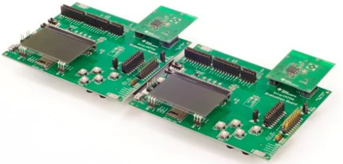
The hardware provided for this project was two sets of SmartRF06EB and CC2650EM, which contains important peripherals and functionalities to replicate, and potentially improve upon, the functionality of the previous project [2]. Each of the sets was acting either as a sender or as a receiver, respectively, and the communication between them was made using Bluetooth.
The Evaluation Board and Evaluation Module, seen in figure 1 [18], are connected using the EM connectors, which, together with the Software Development Kit (SDK), provides an API for the user to interact with the hardware. Depending on what peripheral the user wants to write to/read from there are a number of different I/O methods available, for example, UART (if there is a need for asynchronous receiving or transmission), SPI and I2C (for synchronous data transactions) [19].
Figure 1. The CC2650DK,which includes two sets of SmartRF06EB, each connected with a CC2650EM.
3. 3. 1. SmartRF06EB
The SmartRF06EB is a flexible platform for developing and testing everything from simple I/O operations, for example, pressing a button and making an LED blink or displaying some text on the integrated LCD screen, to interact with a plugged in Radio Frequency Evaluation Modules (RF-EM), such as the CC2650EM. It is possible through the SmartRF06EB operations to read and/or write to the RF-EM’s with using a specific API-Stack for each RF-EM. The EB acts as the main board for interacting with it’s internal peripherals as well as with external integrated devices as the RF-family from TI.
12
3. 3. 2. CC2650 Evaluation Module
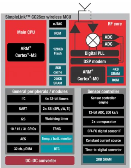
CC2650 is a wireless MCU with internal Bluetooth and Zigbee modules, which its internal structure can be overviewed in figure 2 [20], and is used as a testing platform for wireless communication using the two protocols. Its predecessor is the CC2640 which has the same functionality but without the ZigBee peripherals. CC2650 comes with a low active power for the RF and MCU and is therefore excellent for systems where long battery time is necessary. It also includes a 32-bit ARM Cortex-M3 processor which runs at 48MHz and contains peripherals such as a power sensor controller. The sensor is optimised for interacting with external sensors and to handle analog and digital data autonomously [20].
This MCU is a member of the Evaluation Module family, which in turn is part of the SimpleLink solutions made by TI. Included with the product is an SDK for the Bluetooth Low Energy (BLE) stack and the Zigbee stack [18].
Figure 2. CC2650EM described with a Block Diagram showing the internal structure with its containing
13
3. 3. 3. Accelerometer - BMA250
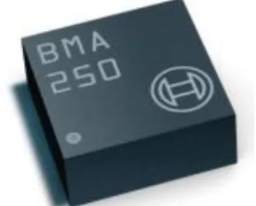
The BMA250 is an accelerometer sensor, whose appearance can be viewed in figure 3 [21], with tri-axial and low-g accelerations with a digital interface, which suits for low-energy applications. The device measures accelerations in three axis and senses things such as, but not limited to, tilt and vibrations. To access it’s internal register for reading or writing data, the digital I/O supports I2C and SPI [21].
Figure 3. The appearance of the accelerometer, BMA250, made by Bosch.
3. 4. Inter-Hardware Communication
Communication with the hardware is done with the specific drivers together with the functionalities that comes bundled with TI-RTOS. The EB handles all interactions with peripherals, such as buttons, LEDs and its different sensors while the EM controls all connections with the Bluetooth and/or the Zigbee. Communication with most peripherals, for example the accelerometer, is done either via SPI, I2C or UART.
The suggested and supported language to implement the functionality in is ANSI C, since it enables programming close to the hardware itself, by using Code Composer Studio (CCS) as the development environment. Since this report focuses on evaluating the data reading frequency and transmission rate to a receiver in comparison with the older system, there won’t be any deeper explanation of the complete BLE-stack except for some specific protocols that handles the transaction itself.
14
3. 4. 1. BLE-Stack API
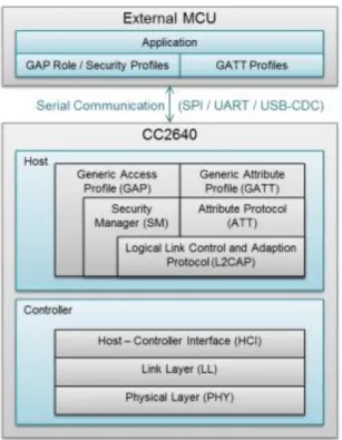
The BLE Stack SDK is developed by Texas Instrument with an API which enables programming the Bluetooth. The BLE-stack consists of layers, which can be overviewed in figure 4 [22], which is divided into two sections, the controller and the Host. These sections manage with the following; The application or profile that interacts with the Bluetooth is placed upon the GAP and GATT layers, where the GAP handles the connection between a transmitting- and a receiving PCBs as for example, detecting advertising devices and connection services, and where the GATT takes care of the data transactions. The security is handled by the security manager in the Host section, which encrypts and decrypts communications for safety reasons and the linking protocol (L2CAP) which encapsulates and transfers data from the lower to the upper layers, such as the GATT, GAP and the Application. The host control interface (HCI) provides communication between the Host and the Controller sections, and finally the physical layer that manage the actual frequency data transaction [22].
15
3. 4. 2. GAP & GATT
The Generic Access Profile (GAP) represents the API which handles functionality regarding connection and communication between device discovery, device access, link establishment and termination, security and other configuration. The GAPRole is a suggested API to be used as an intermediator to the GAP. It uses callback functions that is structured according to the roles a device can have. It can act as a broadcaster, observer, peripheral or a central. The last two roles are of particular interest for this project since it focuses on the connection and data transmission between a sender and a receiver.
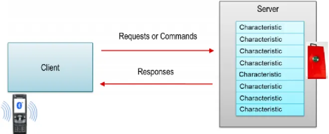
While the GAP handles connection related functionality, the Generic Attribute Profile (GATT) handles the communication between two linked devices. Figure 5 shows the communication between devices with the use of the GATT roles [22]. Data is sent and stored in the memory of the BLE-unit. The GATT profiles can take form as either a GATT Server or a GATT client [22].
Figure 5. Connection relation between a peripheral device, for example a sensorTag, acting as a GATT Server with a
central device, and a smartphone representing the GATT Client.
3. 4. 3. Peripherals
Embedded systems often include additional hardware devices, excluding the processor and memory, some devices vary depending on the application domain while others are essential and more generic, for example timers/counters and serial ports. Devices included directly on the chip is called internal peripherals and the opposite are therefore external peripherals.
Each peripheral device can be accessed through different controls and status registers. The registers represents I/O operations through bits of data, where each has its own specific definition and format. For example there are memory-mapped I/O registers which stores the address values of connected peripherals. These registers can be used to handle the communication between the peripherals and the CPU [23].
16
Communicating with peripherals
SPI and I2C are both based on serial communication, which means that data is handled by a process, similar to a queue system, where each bit is sent sequentially, one at a time. A shift register is an example of the simplest form of a serial communication. For example, two shift registers have a connection where one of them is a transmitter and the second is a receiver where the first handles the clock signal (CLK) and the control signals, known as synchronous connections. This means that the sender synchronise with the receiver by a CLK and also send characters which defines the start and stop [23].
Inter-Integrated Circuit (I2C)
I2C is a commonly used bus in embedded systems due to its low-speed operations, short distance communication and low hardware resource requirement. It is constructed with two bus signals, serial data
(SDA) and serial clock (SCL), where the connection and transactions are initiated by a master which also
uses the clock to control incoming data. The figure 6 shows an example description on a master communicating with multiple slaves via the I2C bus [23].
Unlike SPI, which uses a full duplex architecture, I2C uses a half duplex architecture, which means that the communication can take place in both directions but with only one direction at a time. I2C supports having multiple masters, allowing reading and writing to the same linked slaves and also including collision detection and arbitration to prevent corrupt packets. When a master communicates broadcasting data, including the receiver's address, each slave compares the incoming address with its own to verify to whom it is intended for [23].
I2C is an 8-bit oriented protocol and can bidirectionally transfer data up to 100kbit/s in standard-mode and 3.4 Mbit/s in High-speed Mode [24].Its advantages is that it has good communication with devices that are accessed occasionally and easy to use because of its addressing scheme [25].
Figure 6. Example of an I2C bus with several slaves connected where the master is the Microprocessor. All devices
17
Serial Peripheral Interface (SPI)
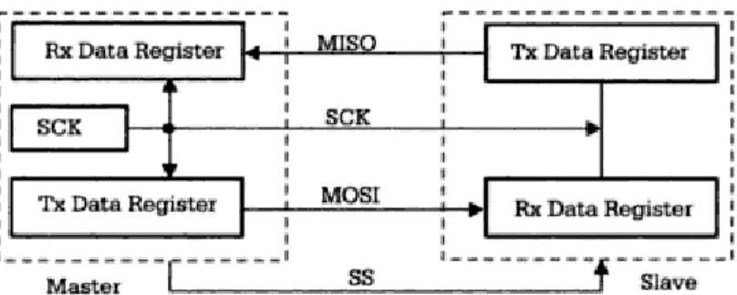
Essentially SPI consists of a pair of shift registers, where you clock data into one shift register while you clock data out of the other. Usually data is written in bytes by having each time 8 clock pulses in succession, but that's not an SPI requirement. It is possible to use word lengths of 16 bits or even 13 bits, if preferred. While in I2C synchronisation is done by using a start sequence, in SPI it is done by sending out a Slave Selection signal (SS), which in turn is for selecting which slave to communicate with. The user can decide after how many clock pulses this is. If the word length is set to use 13 bit words the SS will latch the last clocked in bits after 13 clock pulses. Since the bidirectional data is on two separate lines it's easy to interface. Figure 7 shows the connection between a master and a slave [26].
SPI uses a full duplex architecture [23], meaning that the communication can be done in both directions at the same time. If the master only want to read from the slave, it still has to send “dummy bytes” - the reading and the writing happens on the same line. The master can be connected to one or more slaves and communicates with a specific slave by using hardware signals containing the slave’s address, since it has no support for any device addressing scheme, which also gives the benefit of reducing overhead. The SPI master uses Master Output Slave Input (MOSI) and Master Input Slave Output (MISO) for the communication ports between itself and the slave [23]. The standout advantage of SPI is that it is simple and efficient regarding its full duplex and less overhead than I2C due to differences in address access [25].
Figure 7. Summary of the SPI protocol describing the communication between a master and a slave. Note that the
18
3. 5. Evaluation and Validation
A number of tests was aimed to be performed to assess the viability of this new platform in comparison to the platform used in the previous project. These tests was divided into two categories, one for tests that were performed during the course of the project, at least partially, and one for the tests that are suggested for the future.
Tests that were performed during the course of this project include:
Test time duration before package losses start occurring. Measure how long the device can keep constantly transmitting data over Bluetooth before package losses start occurring. Perform this test on a number of different package per second transmission rates.
Test the maximum distance the two Bluetooth modules can be apart before package loss starts occurring. All Bluetooth communication have a limited range, but is the connection stable all the way up to the cutoff-point or is there a risk of package loss at a certain distance before losing connection?
Evaluate the consistency of performance over a longer period of time. By running a test, which takes a known amount of time, several times in rapid succession it will be possible to see if there is any drop in performance if the system is to remain operational over a long time.
Evaluate the device's ability to withstand external signals. Perform a control test in a "safe"-environment, with little to no other active equipment in close proximity. Perform the same test in an environment with a lot of electronic equipment around and check for discrepancies in performance. Perform the test a third time in an environment with a lot of equipment using Bluetooth traffic, monitor for package loss or reduced operating range.
The following tests remain for future evaluation:
1. Measure the time it takes to read over UART(USB connection) by sending an incrementing number from 0 to 100, making each number a separate package, and calculate the average time for sending a single package over a USB connection.
2. Measure the time it takes to read a single register on the hardware via the I2C communication protocol. Read the registry containing the chip id and send the data over a USB connection. Repeat 100 times and calculate the average time for reading a register.
3. Measure the time it takes to read 9 axis of data. This requires reading from 18 registers: six readings for an accelerometer, six readings for a gyroscope and another six readings for a magnetometer. The six readings performed for each instrument are divided into two readings per x-, y- and z-axis. Bundle these 18 readings into one package and sending it over a USB connection. Repeat 100 times and calculate the average.
4. Identical to the previous test except that the data will be transferred over Bluetooth instead of through a USB connection. Repeat and calculate average time per data package.
5. Analyse the implementation of reading from the registers containing the data from the measuring instruments. Can it be improved upon or shortened without risking the integrity or accuracy of the collected data?
19
6. Test the difference in using a burst transmission of data compared to continuous transmission over Bluetooth. Is there a risk of package loss if the hardware waits for a certain number of packages to have been assembled before sending all of them in a short burst transmission instead of continually sending a package as soon as one is ready? If burst transmission is equally reliable, it would allow the Bluetooth unit to be put into a standby-state between transmissions, thus conserving power for the device as a whole.
7. Test the hardware in several different, reasonable, temperature conditions. Is there a risk that the performance of the device will be affected by differences in temperature while it is in operation? Estimated operating range of the final version of the device is between -20 to 50 degrees Celsius.
8. Test for environmental bias. Check if the device performs consistently in different environments, enclosed spaces, open areas, in or around vegetation or snow.
As the available hardware is also equipped with a ZigBee-module it is advisable to do the initial performance tests (tests 1-4) using this communication protocol and compare it's performance to that of the BLE-module. Initially only a pure performance test will be conducted to check how it performs, but if it appears a reasonable competitor to transmitting the data over Bluetooth, all the tests mentioned above will be performed, including the tests performed during this project, and the results compared to those obtained from the Bluetooth module.
20
4. Implementation
Before attempting to recreate the functionality on the new platform it is necessary to understand the hardware and how to interact with it. Therefore, a fairly large section of time was set aside to study the hardware’s software guide [22] and the examples mentioned within it as well as taking a quick introduction to the structure of TI-RTOS [27] via a set of workshop videos created by Texas Instruments [28]. The knowledge provided by these tutorials made it possible to analyse the contents of the example projects included with the installation of the Code Composer Studio IDE [29]. Unfortunately most of these examples does not appear to be adapted for the hardware provided, and as such testing and analysing these projects in any real sense has been especially difficult. Out of the seven example projects that were tested only two functioned as intended, and unfortunately, neither of these two projects provided any insight into how to communicate with the onboard accelerometer and only limited knowledge on the use of the BLE-stack. Because of this it leaves the project with further challenges, primarily regarding the time limit set for the implementation phase. This affects the process by way of needing to split up the development into several sub goals to be able to discover the right pieces to use for the final system. The rest of the implementation phase would therefore be to do more research and code tests to gradually find a suitable solution for the project.
To ensure that the comparison between the new- and the old platform is as accurate as possible it is necessary to keep the tests as close to identical as can be. Because of this it was determined that communication with the onboard accelerometer would use the I2C protocol,as this was the protocol used in the previous project. A significant amount of time was spent researching I2C, analysing code examples using the I2C protocol and creating new projects that could be tested on the available hardware. After several unsuccessful tests a discussion was had with a party that have more experience on the subject matter. With their help and some deeper analyses of the hardware schematics it was determined that the available hardware is not equipped to handle communication between the hardware and the onboard accelerometer via the I2C protocol [30]. Because of this revelation it is necessary to change the communication protocol to SPI, which will have two major effects on the project. Firstly, the comparison will take place between two projects using two different communication protocols, the results will still be valid but less ideal. Secondly, the current test projects need to be rewritten using this new protocol and, once it’s been determined that they are functional, run through several tests to determine it’s performance.
21
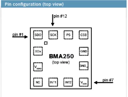
It’s important to note that it is possible to communicate with the accelerometer using I2C communication, but only if it is configured properly. To determine which communication protocol the accelerometer will respond to, SPI or I2C, the protocol select pin (PS pin) as seen in figure 8 [21], need to be connected to the supply voltage for I2C or to ground for SPI. As for it’s connection to the SmartRF06EB, the PS pin is connected to ground. Therefore the I2C protocol is disabled for this particular hardware.Figure 8. Pin layout of the BMA250 Accelerometer used in this project. The most relevant pin is the PS pin as it
determines if the device will communicate via either I2C or SPI.
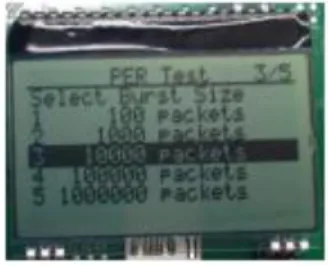
Communication over the BLE-stack has been confirmed to work, testing has been performed on the hardware with the pre-installed packet error rate test [31]. A number of tests were performed at several different transfer rates, the different rates available in this test can be seen in figure 9 [31]. The smallest test performed was of 20 packets/s with a burst size of 10000 packets, all burst sizes that can be used in this test are visible in figure 10 [31]. The test concluded at roughly 8 minutes and 20 seconds with an error rate of 0%. The timing aspect of the test involved a human factor so a small amount of error margin will be unavoidable. The consequent tests of 100000 and 1000000 packet sizes were not performed as they were deemed to take too long, with a calculated length of roughly 83 minutes and 833 minutes respectively.
Figure 9. Figure depicting the available speeds for use in the Packet Error Rate Test. Tests were performed using
22
The available packet rate of 50 packets/s was skipped in favour of the faster 100 packets/s and several tests were performed at this rate with 1000, 10000 and 100000 burst sizes. These tests were performed multiple times to make sure the results were consistent and all tests concluded at roughly their expected time of 10 seconds, 1,7 minutes and 16,5 minutes, with a consistent error rate of 0% across the board. The burst size of 1000000 packets were not tested as the test was calculated to take roughly 2,8 hours to conclude.Figure 10. A summary of the different packet burst sizes available in the Packet Error Rate Test. The primary burst
sizes used for testing were 1000/10000/100000 packets.
To evaluate the impact of distance on the bluetooth communication, the Evaluation Boards were placed next to each other and an error rate test was performed with a transfer rate of 100 packets/second and a burst size of 10000 packets. After this concluded at 0% packets lost, the two EBs were placed at a rough distance of one metre apart and the test was run again. Upon completion the distance was increased to two metres and so on, up to a maximum distance of roughly 5 metres. All tests concluded successfully with a packet loss of 0%. Furthermore, a test was run with a packet rate of 100 packets/second and a burst rate of 100000 packets. During this test, which takes roughly 16,5 minutes to run to completion, the distance between the EBs was altered several times, within the ranges specified earlier. This was done to check if changing the distance between the hardware during operation would have an impact on the communication. This does not seem to be the case as the test concluded with 0% packet loss.
In addition to distance, communication over longer periods of time was also tested. The longest test that had been performed previously (100 packets/s, 100000 burst size), with an estimated completion time of 16,5 minutes were run four times in rapid succession, effectively giving the system a continuous runtime of 66 minutes at the highest available transfer speed. All four tests finished with a 0% packet loss, signifying that communication can be maintained at a speed of 100 packets/s, for at least an hour without risk of losing packets.
Over the course of the project, the system was tested in a number of different situations in regard to external signals. Tests were performed in situations with barely any electronics in the immediate area, as a form of control test. Tests were then performed in an area with a lot of electronics (mobile phones, computers, both laptops and stationary, as well as various measurement instruments used in electronics), with no measurable change in performance or communication stability. Finally, the system was tested in an area with several other systems using bluetooth communication (mobile phones, computers, headphone and tablets), again with no noticeable differences.
23
Based on analysing the code for one of the example projects that includes the use of the accelerometer, none of which actually worked when testing on the available hardware, the base test reads data from the accelerometer every 50ms, or at a rate of 20Hz, which is the same frequency that was attained by the previous project. Therefore it seems reasonable to draw the conclusion that the frequency could be increased with a few modifications to the code, not to mention that this project also included several other functions, for example measuring battery life and analysing key presses. If these other functions could be removed, not only would it decrease the amount of memory used on the hardware to store the code, thereby decreasing the power consumption, but potentially also allow even higher frequencies when reading from the accelerometer since there are fewer tasks that need time to run and fewer interrupts for the RTOS to keep track of.24
5. Result
It was discovered that the accelerometer on this particular hardware is not wired for using the I2C communication protocol, which was used in the previous project. Communication was instead established using the SPI-protocol and transactions were successfully performed over a USB connection. A number of example projects involving the use of the BMA250 accelerometer were analysed and it could be determined that the software read from the accelerometer at a pre-defined sampling rate of 20Hz, while also working on several other tasks simultaneously, therefore performance can at least reach 20Hz.
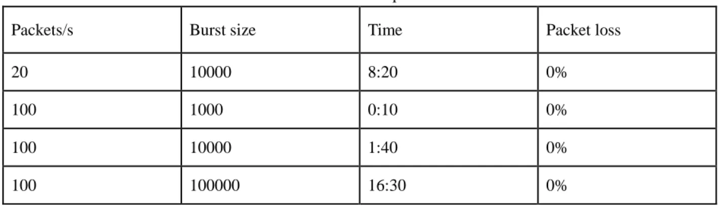
As was mentioned in section 3.5 Evaluation and Validation, several tests were conducted to measure the performance of the new system. The first test that was conducted was to measurethe transfer speed over a Bluetooth connection. These tests were limited to pre-programmed transfer speeds and number of packets to send. A number of consecutive trials were run at the maximum allowed speed of 100 packets/s in with a burst size of 100000 packets, all tests finished after roughly 16,5 minutes with 0% packet loss.
Table 3: Transfer speed test
Packets/s Burst size Time Packet loss
20 10000 8:20 0%
100 1000 0:10 0%
100 10000 1:40 0%
25
The impact of distance on the bluetooth communication was tested by running tests while modifying the distance between the two bluetooth modules. A range of up to 5 metres was tested and found to have no affect on the system. Changing the distance within the 0-5 metres range while transferring data also did not have any measurable impact on the system.Table 4: Distance tests
Distance in metres Packets/s Burst size Time Packet loss
0 100 10000 1:40 0% 1 100 10000 1:40 0% 2 100 10000 1:40 0% 3 100 10000 1:40 0% 4 100 10000 1:40 0% 5 100 10000 1:40 0% Variable 100 10000 1:40 0%
It was confirmed that the system can effectively run for, at least, an hour straight, transferring data at a rate 100 packets/s, without the risk of packet loss or slowing of performance because of running the system for a longer period of time. Each of the four tests run over this hour finished at the calculated time, with a small margin of error based on the human factor, with a 0% packet loss.
Table 5: Duration testing
Test Time Test conclusion
time Packets/s Packet loss
1 0:00 16:5 100 0%
2 16:5 33 100 0%
3 33 49:5 100 0%
4 49:5 66 100 0%
The current system was found to be very resistant to external signals, showing no measurable impact on either the bluetooth communication or performance of the system when in close proximity of other electronics or systems using bluetooth communication.
26
6. Discussion
The primary focus of the work done in this project was twofold. First to test the actual hardware, which included testing the BLE transmission and analyse the communication protocols used to interact with the peripherals, and secondly to implement an improved software solution with consideration of the constraints of the previous middleware.
During experimental coding, using Code Composer Studio and the example projects provided with it, it was discovered that the data acquisition rate, or sampling frequency, for interacting with a peripheral, for example an accelerometer, is a modifiable variable. This, together with the fact that both the SPI and I2C protocols can handle transfer speeds far higher than the ones attained in the previous project, shows that it is not the hardware itself, or the connection to it, that are acting as limiting factors for the system.
Additionally, the results from the bluetooth transaction tests further proves that the actual hardware is not a limitation, being capable of handling much more than is required by the system. Based on these factors, we can draw the conclusion that it is not the hardware that is insufficient for the task, but rather the software platform and, in particular, the ways in which it utilises the hardware that needs to be improved. Therefore, we believe that the outcome of this project strongly indicates that the main goals are feasible. Another part that we believe is needed for the project is to have a fully functional, platform independent, GUI, to enable analysis in a more user friendly environment and also to allow for a larger user group. This was discussed with the employer to implement if the time would allow. But it was set aside since the main goal of this project was to improve and compare the sampling frequency in regards of differences between the software of the previous- and the current system. This is described in more detail in the section of future work.
6. 1. Analysis of interaction with the accelerometer
Based on the two example projects mentioned in the previous sections, that were provided by TI in CCS, we can make a few deductions. In these projects, the sampling frequency was set at a fixed 20Hz, which also was the highest stable performance obtained in the previous project, therefore it is possible to change this value by modifying the code. These examples also contained several other functions and a lot of , for this project, irrelevant code. Therefore it should stand to reason that by removing the superfluous code, we can reduce the amount of overall code stored on the hardware, reduce the drain on the CPU, and therefore, in theory, maximise the performance of the functions that are left. In addition, both communication protocols, I2C and SPI, have a transfer limit far greater than the previously used 20Hz (100Kbps for I2C in standard mode, unlimited for SPI). Therefore, for the purpose of this thesis, using these protocols should not be considered a limiting factor. Rather it seems much more likely that either the complexity of the language used as well as the hardware itself are acting as limiters.
27
6. 2. Indicative results of BLE transactions
The maximum speed recorded during our tests was 100 packets/second with a burst size of 100000 packets. However, these were preprogrammed limits and therefore offered no possibilities of testing the actual limits of what the hardware is capable of. The Bluetooth 4.0 protocol is capable of handling speeds of up to 25 Mbps, which is much greater than what is required for this device to run optimally. Assuming that every package sent is 8 bits large that would still mean that the Bluetooth protocol can handle 3,1 million packets per second. Since the suggested optimal sampling frequency is 1kHz, there are nine axis of data to read, each reading constitutes one package. This equals 9000 packets every second and the limit for the Bluetooth protocol, as mentioned previously is 3,1 million packets per second. Therefore the Bluetooth protocol itself should not be considered a limiting factor. The remaining possible limiters are the BLE-module itself as well as other hardware and the complexity of the implemented software.
The maximum distance between the bluetooth modules during testing was five metres, which is more than necessary for the nodes in the BAN-system to communicate with each other. Interesting to note is that the bluetooth 4.0 protocol supports a theoretical range of at least 61 metres, depending on the bluetooth hardware used [32], but the stability and performance of that connection would need to be thoroughly tested before it can be used in any reliable fashion.
As for the durability of the system, the system ran, effectively, for roughly 60 minutes, transmitting data at the maximum speed available, 100 packets/s. There was no measurable impact on either the stability (0% packet loss) or performance (all tests concluded at the expected time) of the bluetooth communication. Further testing is suggested, but running the system continuously for at least an hour can be done without any risk of data loss or drop in performance.
The provided hardware showed a satisfying degree of resistance to external signals, both in terms of performance and communication stability. Even in close proximity of several other electronical devices, some of which were actively communicating via bluetooth, there were no measurable differences in the performance of the system or the stability of the bluetooth connection between the Evaluation Modules.
28
7. Conclusions
By analysing the gathered knowledge as well as the template code, provided with CCS, and by performing the tests mentioned earlier in this report, it was discovered that it is possible to adjust the rate of computing I/O operations, thereby giving the new software an increased sampling frequency compared to the previous system. The new suggested programming language and platform is also better suited for hardware applications, especially in real-time systems where I/O operations needs to respond as fast as possible. With that in mind, for this project it was more important to achieve a higher sampling frequency, instead of only taking low energy consumption into consideration, where BGScript would have been a good choice. It has also been concluded that the actual BLE hardware is not a limiting factor regarding the wireless transactions. As written in the previous sections, it’s transfer rate is more than enough to provide this system with wireless communication transmission, and because it is part of a BAN architecture, where nodes are intended to be placed on a human body, there won’t be any distance issues, especially since it is capable of handling up to a 60 meter distance for transmissions. Therefore the goal of finding an alternative way to implement a more efficient software system has been accomplished.
On the other hand, something that needs to be taken into consideration, is that since the finished version of the larger project will include reading from an additional two peripherals, gyroscope and magnetometer, it is important to carefully consider the functionality of TI-RTOS, for example how to best use the scheduler, handling of tasks, semaphores and interrupts so that the software will run as smoothly as possible.
29
8. Future Work
There are still some aspects that need to be further explored, for example: complete the development of the new software solution, integrate it with the complete system, perform continuous testing to ensure the performance of the new system is satisfactory and also create a GUI to visualise the sensor data for analysing. While the results of this thesis indicate that the switch to the new platform would give increased performance, the software still needs to be completed before a migration is possible. After moving the system to the new platform it will be necessary to do, or redo, the tests specified in section 4.5
Evaluation and Validation, to make sure that the system performs satisfactory and to minimise the risks of
anything unexpected occurring.
The following sections highlights these aspects of work that still needs to be done together with a few suggestions to consider when continuing the development process.
8. 1. Replication of functionality
Based on the research done it is very likely that the functionality can be replicated on this new platform and therefore the performance will be faster compared to the previous system. Since it is not possible to use I2C for reading/writing data from/to the accelerometer on the SmartRF06EB it is suggested to either change the hardware PCB to a different one that supports reading from the BMA250’s I2C port, or to implement and then analyse the differences between using the SPI on the CC2650DK and the previous system.
In case the project decides to switch to new hardware it will be necessary to set aside some time to understand the hardware, what it’s capabilities are and how to properly communicate with it before starting to implement the software. Otherwise, if it is decided to keep using the current hardware, it is recommended to spend some time looking into the usage of SPI and then start the implementation phase. Regardless of which option is chosen, once the implementation has been completed it will be necessary to perform extensive testing. Including, but not limited to, the tests that were suggested earlier in this thesis.
30
8. 2. GUI
One of the “future work” suggestions from the previous work was to connect the database, which stores the data collected from the sensors, to a GUI which a user can interact with. A possible alternative to the currently available C# GUI was to create a new GUI in Labview, since Labview was designed to be platform independent and can therefore be used on multiple OS, and to be more inline with the development platform used at the ESS-H (Embedded Sensor Systems for Health) department at MDH [1]. The following paragraphs contains a few suggestions on what to keep in mind, in regards to the GUI, when moving forward.
It would be necessary to spend time to understand developing in Labview, design and implement a GUI with the intent of visualising the received data from the database in a gridview, graph and/or to simulate a human shaped object that moves according to the collected data similar to the technology used for motion-capture. It will also be necessary to comprehend the structure of the database, as for example know what datatypes is being used, how the data is stored, and how to transfer the data from the database to Labview. Therefore it is also necessary to know how to connect Labview to an SQL-Database and how to populate the instruments with data from said database.
To ensure that the GUI is intuitive and user-friendly, it is recommended to have several user tests during the design phase, making sure that the users understands how the GUI works, what it does and how to use it. The earlier these aspects are taken into consideration, the greater the possibility that the final version will provide a satisfying experience for the user. Similar tests should also be performed continuously during the implementation phase to make sure that the project is progressing in the right direction, while also accepting feedback for possible adjustments. Making these adjustments during the development phase is considerably easier, less time consuming and less costly.
With the aim of increasing the system’s user-base, developing a simple GUI as a means of making it more user-friendly, additionally removing the programming knowledge requirement would make the system more accessible to a wider group of people. Providing the user with a visual representation of the collected data allows for different ways of interpreting and interacting with the data. Also having an easy way to save data and load it at a later date for verification or comparing it to new data is a powerful tool that should not be forgotten [2].
31
References
[1] ESS-H - Embedded Sensor Systems for Health Research Profile
http://www.es.mdh.se/projects/324-ESS_H___Embedded_Sensor_Systems_for_Health_Research_Profile.
Accessed: 2015-09-20.
[2] L. C. Eriksson & J. S. Willners. Body Area Network with Gait Symmetry Analyses. Master Thesis in Engineering - Robotics. Mälardalens University, 2015.
[3] A. R. Hambley. Electrical Engineering principles and applications 6th ed.
Pearson Education, Inc. 2014. Upper Saddle River, New Jersey 07458. ISBN-13: 978-0-13-311664-9.
[4] P. S. R. Diniz, E. A. B. da Silva. & S. L. Netto. Digital signal processing: System analysis and design 2nd ed.
Published in the United States of America by Cambridge University Press, New York, 2010. ISBN 978-0-51-88775-5.
[5] P. Hellström, L. Eriksson, J Willners, M Folke & M Ekström. Intelligent wireless body area network system for
human motion analysis, 2015. Link Accessed: 2015-09-18.
[6] W. Emmerich. Software Engineering and Middleware: A Roadmap, The Future of Software Engineering. ACM Press 2000, ISBN 1-58113-253-0
[7] BlueGiga. https://www.bluegiga.com/. Accessed: 2015-09-07.
[8] BGScript. http://mt-system.ru/sites/default/files/documents/bluetoothsmartbgscriptdeveloperguide.pdf. Accessed: 2015-09-07.
[9] BGScript.
https://bluegiga.zendesk.com/entries/39332288--REFERENCE-ADC-sampling-performance-on-the-BLE11x-module. Accessed: 2015-09-12.
[10] A. Schüpbach, A. Baumann, T. Roscoe, & S . Peter. Declarative Language Approach to Device Configuration. Journal. ACM Transactions on Computer Systems (TOCS). Vol 30. 2012.
[11] L. Mottola. & G. P. Picco. Programming Wireless Sensor Networks: Fundamental Concepts and State of the Art. University of Trento and Swedish Institute of Computer Science. Vol. 43. Issue 3, Article 19, Page 1. 2011.
[12] I. Akyildiz, W. Su, Y. Sankarasubramaniam. & E. Cayirci. Wireless sensor networks: a survey. Computer
networks, 38(4):393–422, 2002.
[13] Body Area Network (BAN). https://www.techopedia.com/definition/30083/body-area-network-ban Accessed 2015-09-16
[14] Personal Area Network (PAN).
https://www.techopedia.com/definition/5079/personal-area-network-pan.
Accessed: 2015-11-03.
[15] Bluetooth special interest group. http://www.bluetooth.org/. Accessed: 2015-09-12. [16] Mysql. open source database.https://www.mysql.com. Accessed: 2015-09-07.
[17] Texas Instrument. TI-RTOS 2.14. - User’s guide. http://www.ti.com/lit/ug/spruhd4j/spruhd4j.pdf. Accessed: 2015-10-28.
[18] Texas Instrument. CC2650 Development Kit. http://www.ti.com/tool/cc2650dk Accessed: 2015-10-28. [19] Texas Instruments. SmartRF06 Evaluation Board. User’s Guide.
http://www.ti.com/lit/ug/swru321a/swru321a.pdf. Accessed: 2015-10-28.
[20] Texas Instrument. CC2650 Datasheet. http://www.ti.com/lit/ds/symlink/cc2650.pdf Accessed: 2015-10-28. [21] Bosch. BMA250 Accelerometer.
https://ae-bst.resource.bosch.com/media/products/dokumente/bma250/Flyer_BMA250_v5_102010_25052011.pdf
32
[22]Texas Instruments. SimpleLink Bluetooth low energy CC2640 Wireless MCU. Software Developer’s Guide
http://www.ti.com/lit/ug/swru393/swru393.pdf
Accessed: 2015-10-12.
[23] M. Barr & A. Massa. Programming Embedded Systems Second Edition. O'Reilly Media. 2006. Print ISBN: 978-0-596-00983- 0| ISBN 10:0-596-00983-6. [24] NXP. I2C-bus specification and user manual. 2014.
http://www.nxp.com/documents/user_manual/UM10204.pdf.
Accessed: 2015-10-28.
[25] A. P. Godse & D. A. Godse. Microprocessor, Microcontroller & Applications. Technical Publications Pune. 2008.
ISBN 978-81-8431-27-9.
[26] M. Itescu & I. Susnea. Microcontrollers in Practice. Springer Berlin Heidelberg. 2005. ISBN-10 3-540-25301-7.
[27] Texas Instrument. Introduction to the TI-RTOS Kernel Workshop.
http://processors.wiki.ti.com/index.php/Introduction_to_the_TI-RTOS_Kernel_Workshop
Accessed: 2015-10-12.
[28]Texas Instruments. TI-RTOS Workshop.
https://training.ti.com/ti-rtos-workshop-series-1-10-welcome?cu=7475
Accessed: 2015-10-12.
[29] Texas Instruments. Code Composer Studio.
http://www.ti.com/tool/ccstudio
Accessed: 2015-10-12. [30] SmartRF06EB Schematic
http://www.ti.com/lit/df/swrr143/swrr143.pdf Accessed: 2015-10-26
[31]SimpleLink™ CC2650 Development Kit Quick Start Guide
http://www.farnell.com/datasheets/1886742.pdf
Accessed: 2015-10-26
[32] Wi-Fi Direct vs Bluetooth 4.0: A Battle For Supremacy
http://www.pcworld.com/article/208778/Wi_Fi_Direct_vs_Bluetooth_4_0_A_Battle_for_Supremacy.html