THE DEVELOPMENT OF A FRAMELESS
GLASS DOOR MADE FOR WHEEL LOADERS
JOSEFIN HULT
KPP305 - MASTER THESIS
Advanced level/D-level 30cr
Date of presentation: 13th of June 2014
Commissioned by: Volvo Construction Equipment
ABSTRACT
This thesis performed on master level covers an assignment given by the cab division at Volvo Construction Equipment (Eskilstuna, Sweden). The thesis has been carried out by Josefin Hult during the period 2014-01-23 to 2014-05-30 at Mälardalen University. Volvo Construction Equipment manufactures products including wheel loaders, backhoe loaders and articulated haulers. The assignment involves developing the standard door for larger wheel loaders. The current door has a welded frame surrounding the glass that is considered outdated and not cost effective. Volvo Construction Equipment wishes that the door was made in glass in a greater extent. The aim of the assignment has been to generate concepts regarding a glass door that fulfills given requirements. Three research questions have been stated and answered during the process.
The product development process has consisted of three phases: information gathering, concept development process and development of detailed concept. For example, field studies and benchmarking have been performed to gather information about
competitors’ products and the manufacturing and assembling of the current door. Concepts for handrails, sealant and overall door design have been generated in an iterative process. All components of the door have been developed into a detailed concept during the last phase of the process. The process has resulted in a frameless glass door. The concept suggestion consists of; a tempered sheet of glass, a clip list (sealant) that covers the edges of the glass, two different handrails, inner and outer handles, a gas spring, components to attach handrails against the glass, a cover and a lock mechanism.
The major conclusion that is drawn is that it is fully possible to develop a door made in glass in a greater extent than the current door. Many competitors have machines where the door is made in glass in a large extent. This makes it believable that the glass door also will be perceived as timely and more modern and clear.
Recommendations have been developed if there is interest in further development. The recommendations include, among others, development of handrail and test of
prototype to ensure that all requirements are fulfilled.
Figures are produced by the author if not stated otherwise.
Key words: Product development, Wheel Loader, Glass door, Glass, Door, Sealing, Sealant, Concept development, PDP, Construction Equipment
ACKNOWLEDGMENTS
I would like to thank my industrial supervisors Robert Sundkvist (Manager Cab & Operators Environment) and Magnus Fornell (Lead Engineer Hauler Cab) at Volvo CE Eskilstuna and my supervisor at Mälardalen University Bengt Gustafsson (Machine Technician) for all advice and encouragement you have given me!
I would also like to thank Kjell-Eve Bengtsson (Engineer Volvo CE) for helping me with CAD and sharing material, information and foremost your knowledge.
Finally, I would like to thank the whole cab department at Volvo CE Eskilstuna (Sweden). It has been a very rewarding time and the atmosphere you have is something special. Thank you!
Josefin Hult, Eskilstuna (Sweden) 2014-05-30
DICTIONARY
Cabin frame – The beams that forms the frame of the cabin’s doorway.
CAD – Computer Aided Design. A computer software for designing i.e. products. CAST – Common Architecture Shared Technology. A handbook for Volvo Construction
Equipment that describes e.g. interfaces between parts.
CTS – Common Technology Solution. A manual where standards and internal guidelines
from Volvo Construction Equipment are stated that are used when developing products.
DFMA – Design for Manufacture and Assembly. A product development tool that
intends to facilitate manufacturing and assembling.
EPDM – Rubber material often used for sealing.
IDEO – An innovation firm whose product development process has been used as
support during the project.
PD – Product Development.
PDP – Product Development Process. PD-tool – Product Development tool.
Pugh’s method – An evaluation method of products and concepts.
RPS – Reference Point System. A Volvo system made to facilitate manufacturing. Standard door – The current door for larger wheel loaders.
SVID – An industrial design foundation whose product development process has been
used as support during the project.
Volvo CE – Volvo Construction Equipment. WLO – Wheel Loader.
CONTENTS
1.0 Introduction ... 1
1.1 Problem formulation ... 1
1.2 Aim and research questions ... 1
1.2.1 Aim ... 1
1.2.2 Research questions ... 1
1.3 Delimitations ... 2
2. Research methodology ... 3
2.1 Phase 1 - Information gathering ... 3
2.1.1 Databases ... 3
2.1.2 Questionnaire ... 3
2.1.3 Forum search ... 4
2.1.4 Field studies ... 4
2.2 Phase 2 - Concept development process ... 4
2.3 Phase 3 - Development of the detailed concept ... 5
2.3.1 Summarization of the PDP ... 5
2.4 Reliability and validation ... 5
3. Theoretical framework... 6 3.1 Volvo CE ... 6 3.2 What is a WLO? ... 6 3.3 Glass ... 6 3.3.1 Pilkington ... 7 3.3.2 To process glass ... 7 3.4 Sealing ... 7 3.5 Standards ... 7 3.6 Volvo’s systems ... 8 3.6.1 RPS ... 8 3.6.2 CAST ... 8 3.6.3 CTS ... 8 3.7 DFMA ... 8 3.8 Pugh’s method ... 8 3.9 Ergonomics ... 8
3.10 Product development methodologies ... 9
3.10.1 Volvo PDP ... 9
3.10.4 SVID ... 9
4. Applied methodology ... 10
4.1 PHASE 1 - Information-gathering ... 10
4.1.1 Benchmarking ... 10
4.1.2 Ergonomic test ... 12
4.1.3 Description of current door solutions ... 14
4.1.4 Competitors’ products ... 17
4.1.5 Why choose glass at all? ... 19
4.1.6 Costs ... 20
4.1.7 Requirement specification ... 21
4.1.8 Functional analysis ... 22
4.1.9 Evaluation of existing solutions ... 23
4.2 PHASE 2 – Concept development process ... 24
4.2.1 Summarization of the concept development process ... 24
4.2.2 Generating concepts step (1) ... 24
4.2.3 Concept evaluation 1 ... 24
4.2.4 Generating concepts step (2) ... 26
4.2.5 Concept evaluation 2 ... 26
4.2.6 Generating concepts step (3) ... 28
4.2.7 Concept evaluation 3 ... 29
4.3 PHASE 3 – Development of the detailed concept ... 30
4.3.1 Design of handrails ... 30
4.3.2 Choice of sealant ... 30
4.3.3 Choice of handrail holders ... 31
4.3.4 Choice of hinges ... 31
4.3.5 Choice of handles ... 31
4.3.6 Choice of gas spring and its holder ... 31
4.3.7 Choice of lock mechanism parts ... 31
4.3.8 Choice of glass ... 31
4.3.9 Choice of fasteners ... 32
4.3.10 Cover ... 32
4.3.11 The detailed concept in summarization ... 32
5.1.2 Handles ... 34
5.1.3 Hinges ... 35
5.1.4 Handrails ... 35
5.1.5 Handrail holders ... 35
5.1.6 Lock mechanism and its holder... 36
5.1.7 Gas spring and its holder ... 36
5.1.8 Sealant... 36
5.1.9 Rubber protection for components ... 36
5.1.10 Cover ... 37 5.1.11 Fasteners ... 37 5.1.12 RPS ... 37 5.2 Prototype ... 37 5.3 Assumed strength ... 37 5.4 Estimated cost ... 37 6. Analysis ... 38
6.1 Phase 1 - Information gathering ... 38
6.1.1 Field studies ... 38
6.1.2 Forum search ... 38
6.1.3 Ergonomic test ... 38
6.1.4 Questionnaire ... 38
6.1.5 RQ3: Which functions does the wlo door need to fulfill? ... 39
6.1.6 RQ2: What are the arguments for designing a wlo door in glass without a frame? ... 39
6.2 Phase 2 - Concept development process ... 40
6.3 Phase 3 - Development of detailed concept ... 40
6.3.1 RQ 1: How can the wlo door be designed in order to ensure that strength, function and safety requirements are met? ... 40
6.4 Validation against requirement specification ... 42
6.4.1 Summarization of the fulfilled requirements ... 44
7. Conclusions and recommendations ... 45
7.1 Conclusions ... 45 7.1.1. Result ... 45 7.1.2. Method ... 45 7.1.3 Process ... 45 7.2 Recommendations ... 46 7.2.1 Glass ... 46
7.2.2 Vertical handrail ... 46
7.2.3 Sealant... 46
7.2.4 Cover ... 46
7.2.5 Gas spring holder ... 46
7.2.6 Prototype test ... 46
7.2.7 Cost reduction ... 46
7.2.8 Glass door that is perceived as safe ... 46
8. References ... 47
8.1 Literature sources ... 47
8.2 Internet sources ... 47
8.3 Verbal sources ... 50
TABLE OF FIGURES
Figure 1: The standard door ... 1
Figure 2: The PDP ... 5
Figure 3: WLO L250G ©Volvo CE ... 6
Figure 4: Shattered tempered glass ©Universal windows ... 6
Figure 5: Sealing ©DAFA ... 7
Figure 6: Volvo's PDP ©Volvo (2014) ... 9
Figure 7: The mechanical design process ©Ullman (2010, p.82) ... 9
Figure 8: A step in the door manufacturing ... 11
Figure 9: Volvo Articulated Hauler ©Volvo ... 12
Figure 10: The two handrails seen from inside the standard door ... 12
Figure 11: Ergonomic test ... 13
Figure 12: The standard door seen from inside ... 14
Figure 13: A CAD illustration of the standard door... 14
Figure 14: Section view of the frame's profile ... 15
Figure 15: The gas spring ... 15
Figure 16: The current upper hinge ... 15
Figure 17: The outer and inner handle ... 15
Figure 18: The handrails ... 15
Figure 19: L105 Door ... 16
Figure 20: WLO L25F ©Volvo ... 16
Figure 21: Sealant ... 16
Figure 22: Hinges for L20/50 ... 16
Figure 23: ©Fendt, Claas, Valtra ... 17
Figure 24: ©Lännen lundberg, ©Lännen ... 17
Figure 25: ©Huddig, New Holland ... 17
Figure 26: From top left: ©JCB, ©Liu Gong. From bottom left: ©CAT, ©Gehl ... 18
Figure 27: ©John Deere, ©Bosal Sekura ... 18
Figure 28: Cost for standard door ... 20
Figure 29: Evaluated products ... 23
Figure 30: Compact Mobile Crane AC40 ©Bosal Sekura ... 23
Figure 31: Lännen Lundberg 4200LS ©Lännen ... 23
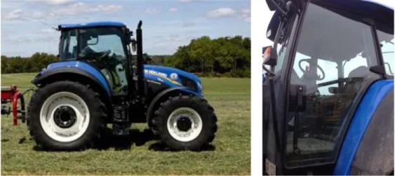
Figure 32: New Holland T5 Electro Command Tractor ©New Holland ... 23
Figure 33: Claas Axos 340-310 ©Claas... 23
Figure 34: Volvo WLO L20F ©Volvo ... 23
Figure 35: Concept 1 and 6 from step (1) ... 25
Figure 36: Evaluation of sealant suggestions in Pugh’s matrix ... 26
Figure 37: Sealant concept 2.1 ... 27
Figure 38: Sealant concept 2.3 ... 27
Figure 39: Sealant concept 2.4 ... 27
Figure 40: Selanat concept 2.5 ... 27
Figure 41: Sealant concept 2.6 ... 27
Figure 42: Combined concept 1 ... 28
Figure 43: Combined concept 2 and 3 ... 28
Figure 44: Combined concept 4 ... 28
Figure 45: Combined concept 5 ... 29
Figure 47: Glass side edge ... 32
Figure 48: Summarization of detailed concept ... 32
Figure 49: Detailed door concept and standard door... 34
Figure 50: Left: Outer handle. Right: Inner handle ... 34
Figure 51: Hinge ... 35
Figure 52: Left: The horizontal handrail right: The vertical handrail ... 35
Figure 53: Handrail holder for pipe ending ... 35
Figure 54: Holder for the vertical handrail attaching to the hinges ... 35
Figure 55: Left: Lock holder. Right: Lock ... 36
Figure 56: Gas spring holder, ball joint anchorage and gas spring ... 36
Figure 57: Sealant profile ... 36
Figure 58: Rubber protection under hinge ... 36
Figure 59: Cover ... 37
Figure 60: Reference points ... 37
1.0 INTRODUCTION
This report summarizes the thesis work at master level that has been carried out by Josefin Hult at Mälardalen University in collaboration with Volvo Construction Equipment (hereinafter named Volvo CE) at the cab division in Eskilstuna (Sweden) during 2014-01-20 to 2014-05-30.
1.1 PROBLEM FORMULATION
The assignment that was given was to redesign the standard door for the larger wheel loaders (WLOs) since the door is not considered cost effective or modern looking. The standard door consists of the main parts that are a steel frame, a tempered sheet of glass, inner and outer handles that connects to a lock, handrails and a gas spring for a safe opening and closing of the door, see figure 1.The assignment has been stated as follows: To redesign or if possible remove the steel frame that surrounds the glass in the current door (standard door) so that the door is made in glass in a greater extent than today. This should be done without risking safety aspects as well as strength and function requirements.
1.2 AIM AND RESEARCH QUESTIONS
The aim of the assignment and the research questions (RQ) that this thesis is built upon is stated below.
1.2.1
A
IMThe purpose of the assignment is to develop the standard door. This should be
performed by generating concepts for the door where it is designed in glass in a larger extent than the current solution, and in the meantime design the door in a cost effective way. The concept shall fulfill the same functions and requirements as the solution today.
1.2.2
R
ESEARCH QUESTIONSThe research questions (RQs) are divided into one main question and two sub questions. The sub questions are intended to help answer the main question of this thesis.
Main question
RQ1. How can the WLO door be designed in order to ensure that strength, function and safety requirements are met?
Sub questions
RQ2. What are the arguments for designing a WLO door in glass without a frame? RQ3. Which functions does the WLO door need to fulfill?
1.3 DELIMITATIONS
In accordance with Volvo CE, the generated concepts should be based on the following aspects:
The original parts for door handles, lock mechanism and gas spring should be used.
The door should express a “modern feeling”.
There should be an inner handle or handrail that acts as an elongation of the entry. Ergonomics needs to be investigated in this respect.
The door needs to fulfill the sealing requirements stated in the internal document CTS “Preferred solutions of doors”.
To provide a safe entering and exiting there needs to be a three-point grip, which means that the operator always shall have support for two feet and one hand or two hands and one foot.
The work will mostly be performed at Volvo CE Eskilstuna but resources will when needed be used from Mälardalen University Eskilstuna during the period 2014-01-20 to 2014-05-30 with in average 40h per week. Time is the biggest constraint. How the different components are being made or how they should be manufactured will, therefore, not be covered. There will also not be any room to find the cost for the concept suggestions, assumptions will instead have to be made. Only if time permits will simulations and calculations be performed, otherwise the concepts will be evaluated against competitors’ products in order to ensure a satisfying quality. If the time and possibility exists, a prototype will be made to test function and design.
The tasks that are considered as prioritized are:
Investigate existing door solutions in aspect to function and design, both products from Volvo CE and competitors.
Collect information about what functions and requirement that the door needs to fulfill.
Investigate what impressions regarding quality and opinions that exist about agricultural machines where the doors and cabins often are designed in glass in a large extent.
2. RESEARCH METHODOLOGY
A broader study has been conducted with quantitative secondary and primary data to answer the RQs. The data has been gathered by using the Volvo CTS database,
databases offered at the Mälardalen University library and finally Internet sources to complement the printed sources (Booth, Colomb and Williams, 2004, p.89). The primary data has been gathered during field studies of both agricultural machinery and
construction equipment, which are described more in more detail below. The project has been divided into three larger phases:
Phase 1: Information gathering
Phase 2: Concept development process Phase 3: Development of the detailed concept
The product development processes (PDPs) by: Ullman (2010), SVID and IDEO (described in section 3.10) have been used as support and a way of structuring the work during the project. Phase 1 is intended to answer the two sub questions (RQ2 and 3) and give deeper understanding of the core of the assignment in order to answer the main question (RQ1) during phase 2 and 3.
2.1 PHASE 1 - INFORMATION GATHERING
The different methods for information gathering are outlined below.
2.1.1
D
ATABASESThe databases Discovery and Google Scholar (Bell, 2006, p.93, p.95; Horne, 2004), provided by the library at Mälardalen University, were used to perform a literature study in order to find information about glass, sealant, (glass) doors and how to experience a product as safe. A database search is proposed by Booth, Colomb and Williams (2004, p.84) to be the first step when gathering information. Search words have included “glass”, “glass door”, “sealing”, “weather strip”, “sealing door”, “seal and door” “semantic design feeling security”, and “product development feeling of safety”. These have been chosen after the advice from Bell (2006, p.93) that refers to Horne (2004) to use specific search words in order to get concrete answers. Focus has primarily been to choose sources that are as new as possible to hold relevance (Booth, Colomb and Williams, 2004, p.89). Unfortunately, no usable information has been found during the database searches given the scope and time limit of this project. The Google search engine has been the primary database when searching for products from competitors, existing component solutions and similar. This is a method that should not be
underestimated according to Bell (2006, p.93) that refers to Horne (2004).
2.1.2
Q
UESTIONNAIREQuantitative information has been gathered by sending out a questionnaire to seven retailers of different agricultural and construction equipment. The main purpose of the questionnaire was not to confirm assumptions but rather to gather as much information as possible about function and design of doors that competitors use and opinions about them. The questionnaire was built on single respond and open questions that according to Bell (2006, p.138) is the type of questions that should be used when the respondents should be able to express their opinions. By having this combination of questions, a broader view on information and opinions about the door could be given. The questions were made with the thought of not being leading or judgmental (Bell, 2006, p.144). Unfortunately, even though reminders were sent out only two responses were received thus weakening the conclusion (Bell, 2006, pp.151; Moser & Kalton, 1971, p. 267-268).
2.1.3
F
ORUM SEARCHQuantitative information has also been gathered by searching in forums, in particular at the forum Maskinisten (The Machinist, authors’ translation). There is a great quantity of different agricultural and construction equipment discussed in this forum (Maskinisten, 2012). By focusing on this forum the opinion has been that if the information is not found here then it is unlikely to be found anywhere else given the time limit and project scope. When searching on the forum it has been considered to be extra important to have a critical mindset and questioning if the sources are reliable (Booth, Colomb and Williams, 2004, p.83). When reading posts and comments it became clear that the majority had the same general opinion, a conclusion was therefore made that the sources could be considered reliable.
2.1.4
F
IELD STUDIESThree different field studies have been performed to gain a greater understanding of both machines from competitors and products offered by Volvo CE today. This was done in order to give the author of this report her own view of the products. The field studies have contributed with primary data that complements the secondary data (Bell, 2006, p.187). The field studies have been unstructured types of observations since there was a clear purpose of the observation (Bell, 2006, p.188). However, since the objects that have been observed have been mostly machines there has not been a real method for observation, rather trying to investigate design and function of the different doors and their components.
Volvo CE Hallsberg (Sweden)
The production and assembling of the standard door were studied by observations in the beginning of the project in order to get a starting point of knowledge. Emphases was on the parts that take the most time to produce and are experienced as difficult in the production so that when generating concepts these parts would be avoided.
Lantmännen Eskilstuna
Lantmännen is a retailer of agricultural machines (Lantmännen, 2014a). A visit to them was made together with the industrial supervisor at Volvo CE with the hope of being able to look closer at the design of the doors. However, the visit was spontaneous and, therefore, unfortunately unplanned.
Volvo Customer Center Eskilstuna
In connection with a machine show at Volvo Customer Center an opportunity to ride along in an articulated hauler was given. During the visit, focus was on how the entry was designed, the general look and impression of the door and how people used the door when they entered and exited the cabin.
2.2 PHASE 2 - CONCEPT DEVELOPMENT PROCESS
The process has been highly iterative with multiple cycles of generated ideas combined with integration of phase 1 whenever more information was needed in order to develop ideas. This phase has had the highest focus and has taken the most time in line with the methodology by IDEO (see section 3.10.2). As support, different product development
Phase 3
2.3 PHASE 3 - DEVELOPMENT OF THE DETAILED CONCEPT
During this phase, priority has been on developing the concept that has been considered the one with the most potential from phase 2 and that answers best to the specified requirements. In order to make sure that the concept does answer to the requirements, discussions have been held with Volvo CE employees several times during the project. The concept development has been done with the help of CAD, which has facilitated finding design opportunities. In the end of the project, the first step towards a prototype was made that aims to test the design and functions of the detailed concept.
2.3.1
S
UMMARIZATION OF THEPDP
The process can be seen as an illustration in figure 2 to provide an overall view of the project. This structure has been followed during the project and is the same as this report is built upon.
2.4 Reliability and validation
To assess the quality of the work in a project there are two terms, reliability and
validation, that expresses how quality can be measured. According to Bell (2006, p.117) reliability is a measurement in what extent an approach generates the same results at different moments but at the same circumstances. The reliability can depending on situation, be measured by different methods. For example, questions can be asked with different formulations but with the same meaning or a test-retest (performing the same test at a different time) can be performed to test if the result is coherent. Validation is, according to Bell (2006, p.117), a measure of how well a question measures what it is intended to measure or describe.
In this project, the reliability and validity can be seen as how likely it is that the same result would be given if the project would be run again. The reliability and validity have been confirmed by using PD-tools for objective evaluations and continuous discussions have been held with Volvo CE employees to create a result that is seen as fulfilling the requirements. With this said, a generated idea is built on knowledge, experience and fantasy which means that it is fully possible that there are other ideas that can be thought of and that would function.
FIGURE 2:THE PDP
Phase 2 Phase 1
3. THEORETICAL FRAMEWORK
The theoretical framework that has been used during the project is outlined in this chapter.
3.1 VOLVO CE
Volvo CE is a part of the Volvo Group and is among the leading manufactures in their field. Their range of products includes, among others: wheel loaders, articulated haulers, backhoe loaders, pavers and compactors. The products are used in different fields, from general construction to forestry and demolition. (Volvo CE, 2014a)
3.2 WHAT IS A WLO?
A WLO stands for a Wheel Loader. It is a construction machine, which comes in different sizes depending on its intended use. A smaller WLO is often referred to as a compact WLO whereas a larger WLO is simply a WLO, see figure 3. A WLO can be used for handling gravel and similar materials. The environment that a WLO
operates in is often rough in the meaning that it is used in more or less all kinds of weather, the surroundings are dirty and the driver is often working long hours. (Volvo CE, 2014b)
3.3 GLASS
Glass is not just a material with one function. Depending on how it is manufactured, glass is made with different mechanical properties and can be used for different
purposes. The purposes’ include pure design objects, windows, façades and much more. One could say that the sky is the limit. (Pilkington, 2014)
Glass is usually divided into three different groups: Float
Hardened (toughened or tempered) Laminated
Float glass is glass in the first step that has not been altered. This glass is easy to break and when breakage occur sharp glass fragments are formed. Tempered or toughened glass is as it sounds, tougher and stronger to withstand forces. This is a sort of safety glass and if breakage occurs the glass will shatter in many small pieces that are not sharp and therefore does not make damage or hurt people, see figure 4.
When making cutouts in tempered glass, the cutouts must be made before the glass is tempered otherwise it will shatter into pieces. Laminated glass has a small
plastic film in between sheets of glass. This makes it harder to break the glass. If breakage does occur, the plastic film collects the glass shatter, which means that there will not be any glass shatter capable of hurting a person. (Hägglöf, 2011)
FIGURE 3:WLOL250G©VOLVOCE
FIGURE 4:SHATTERED TEMPERED GLASS
3.3.1
P
ILKINGTONPilkington is considered one of the larger companies in the field of glass (Pilkington, 2014a). Based on a conversation with a salesperson at Martin G Andersson (a company in the glass industry) it is the recommendations from Pilkington that have been followed in this project.
3.3.2
T
O PROCESS GLASSWhen making holes in a sheet of glass there are a couple of things to keep in mind. The following guideline is taken from Pilkington (2014b) (translation by the author of this thesis) and has been followed when setting the dimensions for the glass sheet.
“Holes and cutouts in glass
The distance from edge to hole with less than 50mm diameter shall be at least 1.5 times the glass thickness, and if the glass is 8mm or more it shall be at least 2 times the thickness. At corners shall the distance in the opposite direction be at least 4 times the glass thickness. If the hole is more than 50mm in diameter, or rectangular, the distance must exceed 0.5 times the hole diameter and the width of the hole. The distance between holes shall be 0.5 times the largest hole diameter, or at least 2-5 times the thickness of the glass. A circular hole must never be larger than a third of the width of the glass. In a rectangular hole can the hole width be maximum a third of the height of the glass sheet. Cutouts from the edge can be maximum 150mm deep and cannot be closer to a corner than 100mm. The radii to a predrilling hole in rectangular cutouts shall be at least equal to the thickness of the glass and never less than 10mm.”(Pilkington, 2014)
3.4 SEALING
A sealant is used when a part, for example, needs to be secured from particles and/or fluids, lower vibrations and keep air pressure. A sealant can consist of different kind of materials but is usually made in some kind of rubber. EPDM is a common alternative since it can be altered to sustain weather, heat, sunlight and more (Takcentrum, 2014). The profile of the sealant depends on where or what needs to be sealed. Depending on where the sealant needs to be applied different alternatives can be used, depending on what the
environment looks like and what materials the sealant will attach to.
For example, the sealant can be attached with adhesives, tape, nails or simply by being hammered into place. The sealants tooth like parts as seen in figure 5 attaches the sealant without use of adhesives or similar.
3.5 STANDARDS
The following standards have been taken into account in this project:
BS EN ISO 2867:2011 Dimensions of handrails and handholds. (Internal document, Volvo CE)
The standard state, among others, distances that is valid between handles/handrails and mounting surfaces.
SS-EN 572 Mechanical properties in glass (Pilkington, 2014c)
Standards included in the document “CAST For Doors Preferred solutions” and the CTS guidelines. (Internal document, Volvo CE)
The document states, among others: - Minimum diameter of handrails is 25mm - Preferred distance around handrails are 50mm
FIGURE 5:SEALING
©DAFA
3.6 VOLVO’S SYSTEMS
Volvo has different systems and standards that are used to ease developing and manufacturing of their products.
3.6.1
RPS
RPS stands for Reference Point System and is used in order to establish reference points from CAD onto a physical object and assist to facilitate manufacturing.
Six different points are needed including the controlling points. The points need to form a triangle so that a coordinate for each axle and point can be located.
(Sundh & Decoo, Cast for Cabs Handbook)
3.6.2 CAST
CAST stands for Common Architecture Shared Technology and can be equated with DFMA (described below). CAST involves the following:
CA: Takes a product’s architecture into account. This involves, for example, how the components are structured and related to each other.
ST: Guidelines that are used in order to share the knowledge about best practices. (Internal document CAST For Doors Preferred solutions, 2011)
3.6.3
CTS
In order to simplify future work, what can be described as a manual is developed. This manual is called a CTS that stands for Common Technology Solution and supports the work when, in this case, new doors are being developed. The manual includes information about standards and solutions that should be used.
(Internal document CAST For Doors Preferred solutions, 2011)
3.7 DFMA
DFMA stands for Design for Manufacturing and Assembling. This PD-tool helps product developers to design a product that facilitates manufacturing and assembling. It consists of various things including where screws should be placed, error proofing, how parts relate to each other and if parts can be integrated. (Boothroyd, Dewhurst and Knight, 2011, p.8-15; Ulrich and Eppinger, p.224-227, 2008)
3.8 PUGH’S METHOD
Pugh’s method, also called the decision-matrix method, can be used when evaluating existing products and wanting to narrow down number of concepts. This PD-tool allows a more objective evaluation because the concepts are evaluated against the
requirement specification and not against feelings and thoughts one can have about an idea. (Ulrich and Eppinger, 2008, pp.130; Ullman, 2010, p.221-224)
3.9 ERGONOMICS
A good working environment for a person that uses WLOs includes among other things that the handles and handrails have a good design and that they are placed in such a way that it is easy to reach and use them. Andersson and Nedergård (2004, p.11) refers to Kroemer and Grandjean (2000) who says, “Controls should be positioned between elbow and shoulder height so they are easy for the operator to reach”. To use a handle or handrail in an ergonomic way means that the hand should not have to be raised above shoulder level (Hägg, Ericson and Odenrik, 2008, p.176).
3.10 PRODUCT DEVELOPMENT METHODOLOGIES
There are different methodologies that can be used in a product development process (PDP). In this project, the methodologies by Volvo, IDEO, Ullman (2010) and SVID have together acted as inspiration, support and provided structure.
3.10.1
V
OLVOPDP
As seen in figure 6, Volvo has a global PDP (the GDP) that consists of six stages. This project can be considered to concern stages one and two where scope of the project is set, requirements are found and concepts are generated and evaluated, where for instance market research is taken into consideration. (Volvo, 2014)
3.10.2
IDEO
IDEO is a design firm that focuses on helping companies to create innovations in order to grow. Their approach is human-centered, which means that the human (the user) is in focus when developing i.e. a new product. Hopefully, by dedicating a larger amount of time to researching a greater understanding of the problem a better solution will arise. (IDEO, 2014)
3.10.3
T
HEM
ECHANICALD
ESIGNP
ROCESS The PDP by Ullman (2010) consists just like Volvo’s PDP of six general phases, see figure 7. This project can be considered to be part of phases one to five where focus has been on phase four. The first phase involves finding the needs that during the later phases should be fulfilled. Phase two aims to plan the project; phase three involves benchmarking and finding customers’ requirements and phase four focuses on generating and evaluating concepts. In phase five, the concept further develops into a product and is evaluated against aspects like DFx (Design for x, where x can be i.e. assembling, manufacturing,environment), costs, production, and performance and robustness. (Ullman, 2010, p.81-90)
3.10.4
SVID
SVID stands for Stiftelsen Svensk Industridesign (The Foundation Swedish Industrial Design, author’s translation). According to SVID the process of developing products is beginning with user studies followed by concepts and visualization. The concepts will then be evaluated and one will be chosen to continue with. That concept will be adjusted and when it is considered to be done the change/new product will be implemented into production. When that is completed, a follow-up will be made in order to find ways to improve next time. This can be seen as quite strict where the process is not highly iterative. (SVID, 2014)
FIGURE 7:THE MECHANICAL DESIGN PROCESS
©ULLMAN (2010, P.82)
4. APPLIED METHODOLOGY
The three phases of this project are outlined in this chapter.4.1 PHASE 1 - INFORMATION-GATHERING
The information-gathering phase has consisted of the following parts: Benchmarking
Ergonomic test Costs
Requirement specification Functional analysis
Evaluation of existing products (competitors and internal)
The information that these parts have provided has helped answer RQ2 and RQ3 and is described below.
4.1.1
B
ENCHMARKINGThe benchmarking has consisted of several parts in accordance with the earlier described method. To start with, a market analysis was performed in order to
understand how other companies have designed their doors. A shorter market analysis is presented in section 4.1.4, the full market analysis can be seen in appendix 1.The competitors that have been investigated are developing machines for agriculture and/or construction equipment and can be seen below:
Agriculture Fendt Valtra Claas Bosal-Sekura Huddig Lännen Construction Equipment CAT JCB Gehl Deere Liugong INTERNET SEARCH
The companies specified above are a selection of the larger competitors based on internal Volvo CE documents, an Internet search of web pages for retailers and a search of the forum Maskinisten. Since these companies have a big range of products, a selection of the products had to be made, see page 17. This selection is based on products that are operating in a similar environment as the WLOs from Volvo CE and that cover a product design range as large as possible. For the full analysis of the competitors’ products, see appendix 1. The findings show that the majority of the competitors’ machines have a door that is very similar to each other and that today it is common that a door is designed in glass in a large extent.
QUESTIONNAIRE
It was desirable to contact professionals who know what the machine users often feel and think about the products, in this case the doors. Therefore, a questionnaire was sent out to seven retailers of different agricultural machines and construction
equipment. Unfortunately, it was hard to receive responses from the retailers’, only two retailers responded. The respondents answered on behalf of JCB, Fendt, Valtra and Claas. Their answers can be seen in appendix 2. Based on the answers from the two respondents their customers have never expressed any opinion about the door. This makes it believed that the door (not depending on brand or door design) is experienced as unproblematic and safe.
FORUM SEARCH
The search at the forum Maskinisten was reviewed in order to collect opinions about doors that the end users may have. Maskinisten is a forum where people with high interests in machines, both agricultural and construction equipment, gathers and discusses thoughts and problems. The whole discussion forum was reviewed without finding any opinion about the doors in the sense of that the user is expressing any difficulty or wants. A conclusion from this is that the door, regardless of company, appears to work well and consumers do not seem to have a problem with either the doors function or design.
FIELD STUDIES
The field studies that have been performed are explained below. Volvo CE Hallsberg (Sweden)
A visit to Volvo CE in Hallsberg was made during the project start-up. At the visit, a Volvo CE employee within welding and engineering showed the production of WLO doors. A step of the production is seen in figure 8. There was a particular focus on how the frame of the current door is welded and how the door is assembled. It became clear that it is the welding that takes most time in the production. The welders discussed the difficulty in some cases to achieve the tolerances that are set, and there are many moments were it is difficult for the welder to get close to the objects that are being welded and to make a good weld joint. It was expressed that it is desirable to avoid welding as far as possible to ease the production.
Lantmännen Eskilstuna
Lantmännen is a retailer of agricultural machines from Fendt, Valtra and Claas
(Lantmännen Maskin, 2014a). The doors on the machines were examined in design, type of glass and what components that were used and how they were positioned and designed. Unfortunately, there was no possibility to open and examine all of the doors since the visit was spontaneous. The doors were made of tempered glass that was clear without any components taking up space or reducing the visibility. The overall design of the doors were similar each other. The overall impression was that the doors are modern and not experienced as being unsafe even though there are no frames because of a smaller sealant that covers the edges.
FIGURE 8:A STEP IN THE DOOR MANUFACTURING
Volvo Customer Center Eskilstuna
A possibility to ride along in a Volvo articulated hauler, see figure 9, was given. It was a simple and unplanned test since the opportunity to ride along came suddenly. However, attention was on the size of the cabin, how the user gets in and out of the cabin and of the general appearance of the door. The observations were made by the author of this thesis. One observation was that of a person exiting out of the cabin. This person chose not to follow the instructions of stepping out with
the face fronting the machine and instead walked out with the face out from the machine and jumped from the last step. This is not considered to be a good way of exiting the cabin because of the risk of injury. When riding along in the hauler it became clear that the space inside the cabin is limited. There is no room for a handrail that goes into the cabin, however, along the glass is no problem. Therefore, size and number of parts have been tried to be kept at a minimum in order to save as much space as possible.
4.1.2
E
RGONOMIC TESTA good working environment includes that it is simple to reach and use handles and handrails. Therefore, a simple test was made to be able to understand how the drivers of a WLO preferably would want to open and close the door, both from the inside and outside of the cabin and whether the handles and handrails are placed in a way that is ergonomically or not. The author of this thesis performed the test of the current door for a WLO. The test was made by sitting in the seat and testing how easy and
comfortable it was to reach and use the handle to open the door from the inside, use the handrail to close the door from the inside and how easy it was to get inside the cabin by using the handrails and outer handle.
LESSON 1
By stepping up on the steps and getting into the cabin the outer grip was tested. One lesson was that the first thing one does is to open the door and wait for it to be fully opened by the
gas spring and then use the inner vertical
handrail on the door as a grip in order to get into the cabin. Therefore, it is important that this handrail is designed in a way that allows the user to reach it from the outside when the user is on their way up into the cabin. This part of the vertical handrail is horizontal and was perceived as a good direction and simpler than a vertical direction would have been. The handrails can be seen in figure 10.
FIGURE 9:VOLVO ARTICULATED HAULER
LESSON 2
One reaches to grab the vertical handrail when sitting in the driver seat and closing the door, see figure 11. Therefore, the vertical handrail needs to be designed and positioned in a way that makes it easy for the user to reach and grab it. As it is now, the handrail is positioned vertically in the part that is made for the user to use for closing the door. This was perceived as more ergonomic and more comfortable for the hand compared to if the whole handrail would have been horizontal.
LESSON 3
Both the inner and the outer handle were perceived as having a good design and position. It was easy to understand how to open the door, both from inside and outside. To have
a continuous grip without parts that the hand can hit into the two handrails should either be attached against each other (this would however not be a continuous grip) or be separated. The horizontal handrail should not end at the backside of the vertical handrail since the user risk hitting the hand on the horizontal handrail. However, since the current handrails are designed with safety and ergonomics in mind the design will not be changed.
CONCLUSION
The current handles and handrails in the door are both well designed and well placed. It is easy to reach and use the handles when one is sitting inside the cabin and it is easy to reach the outer handle when entering the cabin. The placement of these details means that the user does not need to raise its arm over shoulder level or bend the body in a stressful position which is in line with Hägg, Ericson and Odenrick (2008, p.176). These components are therefore considered as fully functional for this project and do not need to be altered provided that the design and position are compatible with the concepts that later are to be developed.
4.1.3
D
ESCRIPTION OF CURRENT DOOR SOLUTIONSThe doors that have special interest in this project are the doors that are used for i.e. the WLO L250G (standard door), the door for compact WLOs i.e. L25F and the door for the WLO L105. These doors are described in the following section. The products from the major competitors have also been in interest where a selection is provided in section 4.1.4, for more details see appendix 1.
STANDARD DOOR
The standard door consists of a welded frame that surrounds the glass. A gas spring is attached to the cabin frame to offer a safe opening and closing by slowing down the door’s movement. The door opens by an inner and an outer handle. These handles are connected to the lock mechanism that is located on the inside of the door. On the inside of the glass are two handrails, a horizontal where the inner handle is attached and a vertical. The vertical handrail has a design that allows the user to get a continuous grip when entering and exiting the cabin. The handrails are welded onto the door frame. The upper right frame corner (seen from front) is slightly bended to be able to be the first corner to abut against the cabin frame and therefore provide a good seal. The standard door can be seen in figures 12 and 13.
COMPONENT DESCRIPTION
Following is a short description of the major components that the standard door consists of.
Frame
Surrounding the glass is a welded frame consisting of steel profiles that the glass is glued onto. The profile can be seen in figure 14. A pretension is welded into the right upper corner so that the corner is the one first to meet the cabin frame. This is preferred in order to get a good seal between the door and the cabin.
Sealing
The current sealant of the door is made of EPDM. The sealant was chosen based on the profile for the frame and is mounted by a hammer in the opening of the frame profile.
Gas spring
The gas spring is welded onto both the cabin frame and the door frame. The gas spring is seen in figure 15.
Glass
The current glass is a sheet of 6mm tempered
glass. This means that if the glass breaks it will shatter in many small pieces without sharp edges, which will not hurt a person. Surrounding the glass is
also a screen print that protects adhesives from UV rays.
Hinges
Two hinges are used to hang the door, see figure 16. Half of each hinge is welded onto the door frame and the other half is welded onto the cabin frame. The current hinges are considered to be fully functional and do not need to be changed during this project as long as they are compatible with the concepts that are
thought of.
Handles
The outer handle can be seen in figure 17. The inner handle is housed in the horizontal handrail and can also be seen in figure 17. These components are connected to each other by among others lock wires that in turn are connected to the lock (not seen in figure).
Handrails
The standard door consists of two handrails, one horizontal and one vertical as seen in figure 18. The horizontal handrail is used foremost to contain the inner handle. The vertical handrail offers the user a continuous grip when especially exiting the door. This handrail is part of the three point grip.
Horizontal handrail
Vertical handrail
FIGURE 14:SECTION VIEW OF
THE FRAME'S PROFILE
FIGURE 15:THE GAS SPRING
FIGURE 16: THE CURRENT UPPER HINGE
FIGURE 17:THE OUTER AND INNER HANDLE Confidential information
DOOR L105
The main difference with this door compared to the standard door is that the cover that hides the lock and its components is smaller. This makes the glass appear clearer. The inner and outer handles are the same as in the
standard door, as well as the two handrails. The door is seen in figure 19.
DOOR FOR COMPACT WLOS
Volvo CE has also compact WLOs. Doors for these machines are often made in glass in a greater extent. The model L25F is as compact WLO and is seen in figure 20. Its door is made entirely in glass. Every component is directly attached into the glass without any panels for the outer handle to be screwed into. This has acted as a great inspiration.
Glass
The glass is like in the standard door a sheet of 6mm tempered glass.
Handles and handrails
The standard components are used as well for this model, being the same as in the standard door.
Sealing
The sealant on this door is glued around the edges acting as a frame. The sealant does not cover the whole edge of the glass as seen in figure 21.
Hinges
The hinges on the L20/50 WLO have a different design compared to the standard door. These are more rounded and have two holes in them to attach the hinges onto the glass and the vertical handrail, see figure 22.
FIGURE 19:L105DOOR
FIGURE 20:WLOL25F ©VOLVO
FIGURE 21:SEALANT
4.1.4
C
OMPETITORS’
PRODUCTSFollowing is a selection of the competitors’ machines that have been analyzed in the market analysis. Concepts developed during phase 2 have been evaluated against these machines. For the full market analysis, please see appendix 1 where a description of each product and more pictures can be seen as well.
AGRICULTURE
First seen are machines from Fendt, Claas and Valtra, these are seen in figure 23. They are similar in their door design with doors made of glass in a large extent.
In figure 24 are Lännen Lundberg and Lännen showed. The doors are considered as more old fashioned with a stiffer impression.
Lastly, machines from Huddig and New Holland are seen in figure 25. These doors are very similar to Fendt, Claas and Valtra and give a modern and airy impression.
CONCLUSION AGRICULTURAL COMPETITORS
Agricultural companies are trying new designs and are not afraid of trying new ways of looks and technical solutions. The designs of the doors are becoming more glass inspired and have a more modern and softer look. The type of environment that tractors and similar products are operating in is in a way more kind compared to construction sites and parts of the machines can therefore be built in less robust materials in a greater extent.
The doors are becoming more and more frameless. Instead, there is often a sealing with a metal strip inside of it. However, there are still a lot of different designs with frames but the door is mostly in one sheet (not divided into multiple sections), which gives a more modern and not so bulky impression. The handles for opening the door from the outside are similar in design.
FIGURE 23:©FENDT,CLAAS,VALTRA
FIGURE 24:©LÄNNEN LUNDBERG,©LÄNNEN
CONSTRUCTION EQUIPMENT
The machines from CAT, JCB, Liu Gong and Gehl as seen in figure 26 have doors that are similar each other. They do not have many visible components, which makes the impression of the door modern and clear.
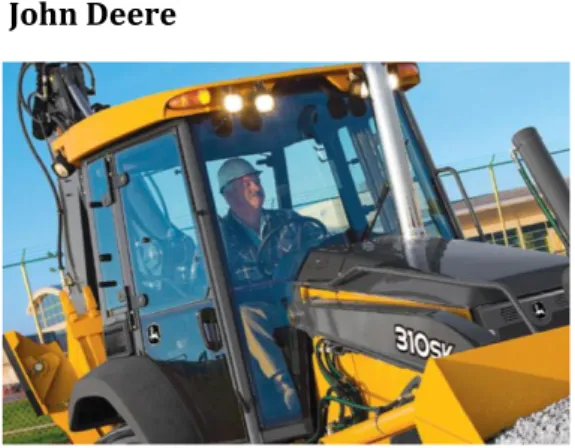
The doors on the machines from John Deere and Bosal Sekura seen in figure 27 are comparable to the ones mentioned above but are divided into two parts, which makes the door appear not as clear as the others do.
CONCLUSION CONSTRUCTION EQUIPMENT COMPETITORS
Companies that offer construction equipment seems to want doors with more glass than before and doors that have solely one sheet of glass instead of multiple sections. So far, it is not as common to have doors without frames as it is for companies that offer products within agriculture. Though, as showed above there are some exceptions, which shows that the trend is leaning against offering frameless doors. The design of the outside handle seems to have a communal shape and is often similar to the handle that the WLOs from Volvo CE have today.
FIGURE 26:FROM TOP LEFT:©JCB,©LIU GONG.FROM BOTTOM LEFT:©CAT,©GEHL
4.1.5
W
HY CHOOSE GLASS AT ALL?
There are different reasons for choosing a design with a large amount of glass. Of course, there is a safety perspective and it is natural to have the feeling of “this is not safe”. However, based on the information gathered from questionnaires and forum search this feeling is not expressed. However, this does not mean that this feeling does not exist. Since glass is a material that is safe when processed correctly, used the right way and with a good design, there is no need to worry. Following are the reasons for why glass is considered as a material that works well for the concepts in this project: Concrete reasons:
More glass means an improved visibility
Easier to assemble when no welding is required
Can lead to a cost reduction since painting and welding of frame is not required Arguments that can be discussed:
Gives a more open and airy impression
Since more glass provides an improved visibility it is likely that the impression is that it feels more open and therefore more airy. This is however a subjective opinion and should not be taken as the truth.
Gives a more modern impression and is timely considering competitors design The trend seems to leaning against doors that are made of glass in a large extent, are peeled down and have few components that are visible.
Compact Volvo CE WLO’s are already implementing glass door solutions To get a consistent appearance of the Volvo CE WLO product range it is assumed that a consistent door design is preferred. Since compact Volvo CE WLO’s have doors made in glass in a large extent, the standard door is considered to be able to have a similar design.
4.1.6
C
OSTSThe cost for the standard door for a WLO is approximately 2 100 SEK. The major expenditure items are the profiles for the frame (calculated 407 SEK), panels (176 SEK), adhesives (145 SEK), cover (129 SEK) and a plate (129 SEK). A big expenditure is also the painting (approx. 300 SEK). The whole list of costs can be seen in figure 28.
To minimize the cost this project has focused on: - Fewer articles
- Standardized articles
- Easy assembling that saves production time
FIGURE 28:COST FOR STANDARD DOOR Confidential information
4.1.7
R
EQUIREMENT SPECIFICATIONA requirement specification has been made that is based on the information discussed during the different field studies and on CTS Documents. The specification can be fully seen in appendix 3. The following points have been prioritized and are copied from the CTS “Preferred solution of doors”:
“ 1.2. Air tightness
Ability to keep inside Cab pressure of 50Pa, total Cab test (Acc. to ISO 10263:1994 Earth - moving machinery - Operator enclosure environment. 3.1 Position of handle
The handle should be positioned in such a way that visibility through the door is not impaired.
3.2 Position of handrail
3.2.1 Handrail should be positioned in such a way that visibility through the door is not impaired.
3.2.2 It is important to try to have long handrails without attachment points on the middle so the operator doesn’t have to change grip so often.
3.3 Three point grip
The standard states that the operator always shall have a three point grip i.e. always have support for two feet and one hand or two hands and one foot.
5.4.4 Diameter
Minimum handrail diameter in the standard is 20 mm and recommended is 25 mm. In Volvo, we shall use 25 mm as much as possible. Thinner handrails shall only be used when space is limited.
5.4.5 Space around handrails
Space around handrails and handles is recommended to be 50 mm and minimum is 40 mm. It is not totally clear in the standard when it is applicable, but we use it on all handrails and controls that the operator grab. “
(Volvo CE, CTS Preferred solutions of doors) The requirement specification is confidential.
4.1.8
F
UNCTIONAL ANALYSISThe functions that the door needs to meet were analyzed based on the requirement specification and the current door. A door is a very common product and its functions can be considered being obvious. In this case, there are also functions that involve having the user entering and exiting the cabin in a safe way.
Following is the function analysis:
Main function
(A) Enclose the cab space/area (a limited space)
Sub function
(A.1) Enable entering and exiting
(A.2) Enable isolation from within (i.e. being able to close (open) door from inside cabin) (A.3) Enable improved visibility
(A.4) Enable support inside cabin
(A.5) Being able to open door from outside
Support function
(A.1-1) Offer a safe handle/grip for ingress and egress
(A.1-2) The door provides an extension of the ingress and egress (A.2-1) The inner handle needs to have an ergonomic design (A.2-2) The inner handle needs to have an ergonomic placement (A.3-1) –
(A.4-1) The inner handrails needs to have an ergonomic design (A.4-2) The inner handrails needs to have an ergonomic placement (A.5-1) The outer handle needs to have an ergonomic design (A.5-2) The outer handle needs to have an ergonomic placement
4.1.9
E
VALUATION OF EXISTING SOLUTIONSThe competitors’ products that were specified in section 4.1.4 have been evaluated and compared against each other and against the standard door in how well they fulfill the requirements. The evaluation was made with Pugh’s matrix and can be seen in appendix 4. A list of the products that have been compared is seen in figure 29. The requirements are the same as in the requirement specification and are weighed after importance based on the information that has been gathered. The evaluation has been made solely based on product pictures, no tests have been performed. The ones considered to fulfill the requirements the least were Bosal Sekura Compact Mobile Crane AC40 (figure 30) and Lännen Lundberg 4200Ls (figure 31). These ones were, for example, considered to
not ease manufacturing and assembling. Claas Axos 340-310 (figure 32) and New Holland T5 Electro Command Tractor (figure 33) are the ones that were considered to fulfill the
requirements the most. These are considered to be very similar to the reference Volvo CE WLO L20F (figure 34) with the one exception of appearing to protect the glass slightly more. For pictures of the products evaluated, see appendix 1.
FIGURE 34:VOLVO WLOL20F
FIGURE 30:COMPACT MOBILE CRANE AC40 ©BOSAL SEKURA
FIGURE 31:LÄNNEN LUNDBERG 4200LS ©LÄNNEN
FIGURE 29:EVALUATED PRODUCTS
FIGURE 33:CLAAS AXOS 340-310©CLAAS FIGURE 32:NEWHOLLANDT5ELECTROCOMMANDTRACTOR ©NEW HOLLAND
4.2 PHASE 2 – CONCEPT DEVELOPMENT PROCESS
Concepts have been developed for both the door as a whole as well as for different components in several stages in an iterative process. The stages will be explained during this chapter. However, for a better understanding of the process a short summarization is being presented first.
4.2.1
S
UMMARIZATION OF THE CONCEPT DEVELOPMENT PROCESSThe aim of this project was, when starting this project, to develop a door made in glass in a greater extent than the current solution and where the handrails could be
redesigned in order to function with the glass design. With this in mind, concepts covering the whole door and ideas for the handrails were generated and evaluated (1). At the same time, the ergonomic test was performed where the main insight was that the current design and position of the handrails should be kept. This meant that the ideas that were thought of for the handrails were put aside. Instead, focus shifted in order to find what ways the door could be sealed. Different solutions that exist today were looked into and alternatives that were thought to work for this context were stated and evaluated (2). When evaluating the sealant alternatives and overall door concepts, discussions led to the opinion that the hinges that are used today should be used for the new door as well. Since the door at this point is fully in glass the opinions were that the vertical handrail needs to be connected in both of the hinges. This in turn led to that the handrail needed to be redesigned, something that earlier was thought of as unnecessary and that should be avoided since the handrail is designed for ergonomics and safety reasons. Since the handrail needed to be connected with the hinges, ideas from (1) and sealing suggestions from (2) were combined in order to find new overall concepts including the handrail (3). However, at a new evaluation the redesign of the handrail was thought of as not fulfilling the requirements. At this point, a decision was made to disregard the requirement of a three-point grip and, therefore, not lay more time on designing the handrail. Instead, focus was to complete the concept for the whole door and develop a prototype were the functions could be tested, which is the final phase of this process (phase 3).
4.2.2
G
ENERATING CONCEPTS STEP(1)
In total, ten different concepts were thought of for the whole door/handrails. Handmade sketches and a short description of those concepts can be seen in appendix 5. There are notes on the sketches, though they are in Swedish. However, during the project focus shifted and a decision was made to use the original handles and handrails, which means that concepts for these parts did not become more elaborated.
4.2.3
C
ONCEPT EVALUATION1
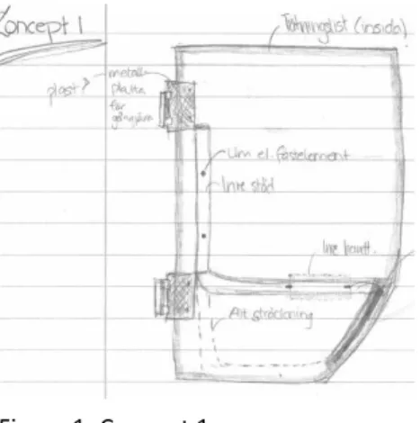
While the concepts were generated a decision was made to not continue to focus on further developing the handles and handrails. This meant that no evaluation was made for these concepts. The concepts that concern the door in general were evaluated against the requirement specification in order to assess which concepts that had potential and should be further developed. This was a smaller evaluation that only intended to provide a foundation for plausible solutions. The concepts that were thought as most probable were number 1 and 6. These can be seen in figure 35 and are described below.
Concept 1 Whole door (step 1)
The door is made entirely in glass without a frame, unlike the standard door. On the inside of the glass is a sealant attached with glue. There is only one handrail that is shaped in a continuous pipe. This allows the user to use the handrail both for support when entering and exiting and to use it to close the door. This would increase the feeling of a glass door. The handrail is attached against the glass with either glue or screws. To get a door that is perceived as a complete glass door the number of details in the glass should be kept as low as possible. A thought was therefore to hide the outer handle and its lock wire inside the pipe frame. However, since the assembling of these parts
involves screws and nuts that manually need to be positioned this part of the concept is not feasible.
Concept 6 Whole door (step 1)
This concept involves two handrails (one vertical and one horizontal) that possibly are welded together. The vertical handrail is attached in both of the hinges. The horizontal handrail is similar to the original with the inner handle hidden inside of the handrail. A cover is used to hide the lock wires etc. that the handles and lock are connected to. The concept is seen in figure 35.
These concepts were as described before plausible solutions that have been further developed during the PDP.
4.2.4
G
ENERATING CONCEPTS STEP(2)
The next step was to generate concepts for the sealant. Based on the information that was found about ways of attaching a sealant and how it can be designed, concepts that were thought to function were generated. The following input was used when
generating ideas.
- The sealant can be attached with tape, screws, adhesives or with tooth like parts that is in the sealant’s design, see figure 5 (page 7).
- Clip list with steel core and cellular rubber for increased stability - Clamping profile/Glazing list
Nine different sealant concepts were thought of. Out of these nine, three were for sealant attached against the cabin frame and the remaining six are for sealant attached against the glass. All concepts can be seen in appendix 6 with a short description.
4.2.5
C
ONCEPT EVALUATION2
The concepts were evaluated in Pugh’s matrix and can be seen in figure 36. It became clear that the most suitable solutions were the ones were the sealant is attached against the glass, not the cabin frame. Mostly this is because it is believed to be easier to get stuck in, and step on, the sealant attached to the cabin frame, thus causing damage on the sealant as well as irritation for the user. The whole Pugh’s matrix can be seen in appendix 7. The requirements that the concepts were evaluated against are
requirements that are based on the information gathered in phase 1 about sealants and how the sealant needs to function. The reference was the current solution of a weather strip that is mounted in the profile of the doorframe. The requirements are partly subjective, which makes the evaluation more subjective than if the requirements would have been hard facts.
CHOICE OF SEALING CONCEPTS
From the evaluation five concepts were considered to go through to the next step and were discussed with Volvo CE employees, see description and figure 37-41 below. There are notes on the sketches, they are in Swedish though.
Concept 2.1
A rubber sealing is glued along the inside of the glass edges. It does not surround the entire edge. This concept is a base concept on which the other concepts are built upon. See figure 37.
Concept 2.3
This concept involves a clamping profile (also called glazing strip), normally in hard plastic, that is U-shaped and surrounds all of the edges of the glass. The profile is attached with toothlike parts that mean that no glue or tape is needed. See figure 38.
Concept 2.4
A continuation on concept 2.3. An aluminum fronted profile with rubber inside that is glued against the glass. The profile covers all edges. See figure 39.
Concept 2.5
A clamping profile with extra sealing against the cabin frame in form of a weather strip. The sealing is attached as concept 2.3 with toothlike parts against the glass (no glue or tape needed). See figure 40.
Concept 2.6
Similar to concept 2.1 but has an L-shape that surrounds the outer edge and the front side. The profile is rounded and taped against the glass. See figure 41.
These concepts were taken to the next step (3), which is described in the next section.
FIGURE 37:SEALANT CONCEPT 2.1
FIGURE 38:SEALANT CONCEPT 2.3
FIGURE 39:SEALANT CONCEPT 2.4
FIGURE 40:SELANAT CONCEPT 2.5
4.2.6
G
ENERATING CONCEPTS STEP(3)
After the first two steps, step (1) and (2), concepts for both the whole door and the sealing had been generated. After the evaluation of those concepts, the concepts that were thought as the best were combined. This resulted in five new concepts (based on the whole door, sealant and new design of the vertical handrail) that were thought as better suited. These concepts were presented for the industrial supervisor and a Volvo CE colleague. The concepts are partly alike with sometimes component solutions in each making parts of the concepts similar. Larger sketches of the concepts can be seen in appendix 8.
Concept 1
This concept concerns a door made entirely in glass with a clamping profile or a glued U-shaped profile list that surrounds all glass edges with either a rectangular or a circular form. There are two handrails, one vertical and one horizontal. The horizontal handrail holds the inner handle. The vertical handrail is formed as the original handrail. If the sealant is glued against the glass, a plastic film is needed to protect the glue from UV-rays. This film could be slightly enlarged to give the impression of a frame and by that increase the feeling of that the door is safe to use. The outer and inner handles are the standard components. See figure 42.
Concept 2 and 3
These concepts are the same as concept 1 but the sealant suggestions are thinner. The sealant could either be glued on the inside of the glass, not covering the edge, or a L-shaped taped sealant that would leave a sharp edge in the corners. It can also be a clamping profile that covers all edges and is attached without glue or tape. The glass corners are rounded, not sharp, to give a softer look and at the same time decrease the risk of tension. The difference between concept 2 and 3 are the sealant suggestions for the whole door. See figure 43.
Concept 4
This concept suggests a door that is partially framed. The frame covers the left and upper side of the glass. This is assumed to ease the pretension in the upper right corner (seen from front) and provide a good seal against the cabin frame. The glass is glued against the frame. See figure 44.
FIGURE 42:COMBINED CONCEPT 1