V¨
aster˚
as, Sweden
Thesis for the Degree of Master of Science (60 credits) in Computer
Science with Specialization in Software Engineering 30.0 credits
AUTOMATIC GENERATION OF
CONFIGURATION FILES FOR
PRODUCT FAMILIES
Enxhi Ferko
efo19001@student.mdh.se
Examiner: Antonio Cicchetti
M¨
alardalen University, V¨
aster˚
as, Sweden
Supervisors: Jan Carlson
M¨
alardalen University, V¨
aster˚
as, Sweden
Company supervisor: Zulqarnain Haider,
Bombardier Transportation, V¨
aster˚
as, Sweden
Abstract
Over the past years, many software industries have adapted the Software Product Line(SPL) as a paradigm that empowers software reuse by exploiting software similarities and managing variabil-ities to enable high-quality deliverables with a shorter time to market. Nevertheless, the lifecycle of SPL development often faces complex tasks. Creating a specific product from the product family is the main challenge. One way towards product realization is through configuration files. Still, manually creating configuration files for each product is an error-prone and time-consuming activ-ity. Therefore, this thesis proposes a variability modeling approach that shall enable an automatic generation of the configuration files for a single product. We conduct a thorough investigation on how to model variability to support automatic generation of the configuration files, introduce four essential decisions related to variability expression, features, constraints and configuration transformation, and present a number of alternative solutions to these decisions. Moreover, we identify evolution scenarios of SPL and evaluate the decisions concerning the scenarios. Finally, a validation of the approach in an industrial case study provided by Bombardier Transportation is presented.
Acknowledgments
First, I would like to express my profound gratitude to my supervisors, Jan Carlson and Zulqarnain Haider. I appreciate their guidance and the fruitful discussions that have been crucial in the completion of the thesis.
I would also like to thank Inderjeet Singh, for giving me the opportunity to be part of Aventra team at Bombardier Transportation as a master thesis student, and offering his continuous support and motivation.
Thank you, professor Elinda for leading me toward this great experience as a student at M¨alardalen University.
Finally, I must express my deepest gratitude to my dearest ones, friends and family. Thank you for believing in me and always inspiring me to do my best!
Table of Contents
1. Introduction 3
1.1 Problem Formulation and Goal . . . 3
1.2 Thesis Outline . . . 4
2. Background 5 2.1 Introduction to Software Product Lines . . . 5
2.1.1 Domain Engineering . . . 6
2.1.2 Application Engineering . . . 7
2.1.3 Variability Management . . . 7
2.1.4 FeatureIDE Tool . . . 8
2.2 Model-Driven Engineering . . . 9
2.2.1 Models and Metamodels . . . 9
2.2.2 Eclipse Modeling Framework . . . 10
2.2.3 Model to text transformation . . . 11
3. Related Work 12 4. Method 13 5. A systematic approach for automatic generation of configuration files 14 5.1 Identified decisions . . . 14
5.1.1 Variability expression . . . 15
5.1.2 Including secondary features in the variability model . . . 15
5.1.3 Utilization degree of constraints . . . 15
5.1.4 Translation from configuration to configuration files . . . 16
5.2 Evolution of SPL . . . 17
5.2.1 Types of evolution . . . 17
5.2.2 Scenarios of evolution . . . 18
5.3 Evaluation of identified decisions considering SPL evolution . . . 20
6. Case Study in a railway transportation domain 23 6.1 High level description of the system under study . . . 23
6.2 Data collection and data analysis . . . 24
6.3 Validation of proposed approach . . . 26
6.3.1 Modeling variability . . . 27
6.3.2 Modeling constraints . . . 29
6.3.3 Product configuration . . . 31
6.3.4 Tool implementation: Configuration file generator . . . 33
7. Discussion and Limitations 35
8. Conclusion and Future work 37
List of Figures
1 Single application development vs Product line development (adapted from [1]) . . 5
2 SPLE framework (adapted from [2]) . . . 6
3 Feature model for the mobile phone domain (adapted from [3]) . . . 8
4 Four-layer framework of MDE. (adapted from [4]) . . . 10
5 The Ecore meta-metamodel. (adapted from [5]) . . . 10
6 Mapping decisions to the SPL process . . . 14
7 Scenarios of evolution in a simple SPL . . . 19
8 Simple metamodel in EMF for train SPL . . . 20
9 Instance of the metamodel in Figure 8 . . . 21
10 Acceleo template for generating XML configuration file . . . 22
11 Aventra product family . . . 24
12 Configuration file for LOT5carDV . . . 26
13 Feature Model of Aventra: Primary Features . . . 27
14 Feature Model of Aventra: Secondary Features . . . 28
15 Constraints in Aventra feature model . . . 29
16 Tree contraints in the configuration editor for LOT4carDV . . . 31
17 Cross-tree contraints in the configuration editor for LOT4carDV . . . 32
18 The format of the configured product LOT4carDV in FeatureIDE . . . 32
19 Translation file illustration . . . 33
List of Tables
1 Important decisions for generation of configuration files . . . 17
2 Evaluation of identified decisions considering SPL evolution . . . 22
3 Configuration parameters and their values . . . 25
4 Technical values for LOT5carDV . . . 26
1.
Introduction
The rapid advancements in software engineering and the significant increase in the need for largescale systems generate a complicated problem in their development due to complexity growth. Over the years, many software companies have focused their product development within specific domains, and most of the software products they promote have common or very similar function-alities. Therefore reusing already developed software or parts of it is the core of benefiting from problems solved earlier in similar circumstances. A relevant solution to manage software reuse in these types of systems, which share a common domain, is Software Product Lines (SPL), also called Software Product Family.
SPL is a software development paradigm where a single software is developed to meet the needs of several products with similarities and variabilities running within a product family. Thus, SPL exploits the commonalities of the different products (also referred to as product variants) belonging to the product family to decrease the overall cost meanwhile providing a higher quality and shorter time of development. This leads to a substantial adaption of SPL use in the software industry. [6]. Nevertheless, the lifecycle of SPL development often faces complex tasks and difficulties. The development of SPL includes modeling the variabilities and commonalities of a product family and using the model as an input to the second phase of configuring and deriving particular products from the shared architecture. The derivation of products remains a challenge because the config-uration of product families and creating a specific product is often manual, time-consuming and error-prone.
Several authors [1, 7, 3, 8, 9, 10, 11] have recognized the importance of automating the con-figuration process of single products and have proposed different approaches also described in the related work section. Most of the approaches are focused on the technical requirements and have proposed a framework or a software tool for automating the derivation process of single prod-ucts. However, to the best of our knowledge, little effort is invested in specifying a straightforward method for modeling the variability to support the automatic generation of configuration files.
Therefore, the purpose of this thesis work is to investigate how to model the variability and define systematic steps throughout the process of developing a product family to support the automatic derivation of the configuration files for a SPL, reducing complexities as well as shortening the time of the development life cycle. To achieve this, we have analyzed an industrial case product family and have identified four essential decisions motivating benefits and drawbacks with respect to evolution of SPL and support for automatic generation of configuration files. Furthermore, we have evaluated our proposed approach modeling the variability of the case study and implemented a helper tool to generate the configuration files. A more thorough explanation of the problem statement is described in the following section.
1.1
Problem Formulation and Goal
First, we will define to what we refer as configuration and configuration file throughout the report and then further explain the problem. One configuration represents a valid selection of features from a SPL variability model with respect to constraints and dependencies specified in the design to identify a single product derived from the product family [12]. Whereas a configuration file is part of the concrete realization of software that at runtime determines some aspect of the software. For instance, it can be an XML file with different configuration parameters related to selected features from product configuration that enables different parts of the same source code used for product families.
SPL differentiates between two development processes being Domain Engineering and Applica-tion Engineering. Domain Engineering, also known as core assets development, is responsible for defining the commonality and variability of the product line. Application engineering, also known as product development, uses the core assets to derive a single product from the software product family adding constraints to match each product’s additional requirements and functionalities [13]. The linking point to both processes is the management of the variability across the product line. Modeling techniques are used to master the complexity and variability of such systems.
Once the SPL model is designed, one way to derive an individual product is by means of configuration files. Other options are to automatically generate code from the configurations of
the products or select different components/existing libraries based on the set of features contained in the configuration.
Our work is focused on configuration files and aims to propose a variability modeling approach which shall enable an automatic generation of configuration files for a single product. The goals of our thesis work are described as below:
– Finding a practical and effective approach for automatic generation of configurations files that would be quick to develop, easy to maintain and easy to validate the correctness of the transformation.
– Alternatively, evaluating different alternatives identified with respect to the desired proper-ties.
More specifically, we want to define some systematic steps for the development of a software product line that supports the automatic generation of configuration files at the same time being scalable, robust and easy to maintain. With this in mind, we have formulated the following research question:
– RQ: How to model the variability of a SPL for an extendable and robust solution to support automatic generation of configuration files?
All the steps from modeling, designing, implementation and selecting the toolchain of soft-ware that would make the generation of the configuration files possible, will be demonstrated and evaluated with a case study on the Train Control and Management System (TCMS) at Bom-bardier Transportation Sweden AB. TCMS is a complex system with multiple types of software and hardware such as controller boards, I/O units and Human Machine Interfaces (HMIs), which is responsible for the vehicle and train control including onboard communication of other subsystems, passenger information, and entertainment functions.
1.2
Thesis Outline
This thesis work is organized in 8 chapters. In Chapter 1, we introduce the area and the topic of our work, emphasizing our research goals and motivation. In Chapter 2, we present all necessary background that the reader needs to know to better understand our work. The information related to SPL, model-driven engineering and tools that we have used is presented there. In Chapter 3 we summarize the related work we have studied to accomplish this research. In Chapter 4 we describe and motivate the research method that we have used to conduct the thesis work. In Chapter 5 we introduce our approach for automatic generation of configuration files to evaluate the approach with a case study in Chapter 6. In Chapter 7 we answer the research question and present the limitations of our work, to conclude the report with conclusions and future work in Chapter 8.
2.
Background
In this chapter, we provide the basics related to software product lines as well as an introduction of the FeatureIDE tool in Section 2.1. To continue with a brief introduction of model-driven engineering, Eclipse Modeling Framework (EMF) and Model transformation in Section 2.2.
2.1
Introduction to Software Product Lines
Single application development aims to create a single software based on the preliminary ments provided by the customer. Traditional software engineering includes analyzing the require-ments, development, and maintenance of the software. This approach requires following all the steps for each individual product, and it is inevitable in the case where the software product is unique and does not share any feature with already developed products. However, most of the software development organizations focus on specific domains, and the products they develop have similar or the same requirements for specific parts of the software. In this case, developing every-thing from scratch affects the main challenges that companies face today being cost, development time and software quality. Software Product Line Engineering is proposed as a solution to embrace software development reuse [1].
A Software Product Line (SPL) is “a set of software-intensive systems that share a common, managed set of features satisfying the specific needs of particular market segment or mission and that are developed from a common set of core assets [artifacts] in prescribed way” [14].
Figure 1 depicts the differences between single application development and software product line development. As it is shown in Figure 1, more effort is required up-front in SPL develop-ment. Instead of developing every single product based on its requirements as in single application development, a thorough analysis of all the product requirements is essential in product line devel-opment. It specifies the domain, and from there Family Engineering will derive Domain Artifact Base. This process is needed to create the also called shared architecture, which defines common-ality and variability of the product line. The construction of a single product later is possible from product derivation using the artifacts and adding specific constrains for additional requirements. In the best scenario, it will require only little effort and implementation deriving a specific product reusing artifacts. Feedback is sent to the Family Engineering process after each product is de-rived to maintain the shared assets and also to improve software development using the methods of the product line approach. The entire process of developing software product lines is divided into two sub-processes Domain Engineering and Application Engineering that are described more thoroughly in the next section.
As briefly explained in the previous paragraph, Product line development consist of two main processes being Domain Engineering (creating artifacts) and Application Engineering (deriving products). The framework in Figure 2 explains the life cycle of Domain Engineering and Applica-tion Engineering.
Figure 2: SPLE framework (adapted from [2])
2.1.1 Domain Engineering
Domain Engineering is the process of SPL engineering that is responsible for identifying, clas-sifying and documenting the commonality and variability of the product line [2]. As shown in the upper half of Figure 2, the life cycle of Domain Engineering starts with Product Management which includes a domain analysis and is responsible for defining the scope of product line [13]. Several accouterments are taken into consideration in this phase as cost estimation and benefits which are evaluated from business and technical experts. It is one of the most critical steps as it directly affects the economic profits of the product line. For instance, if the scope of the software product line is too broad, there is a chance for the artifacts to become too generic and deriving a single product would require much effort. Differently, if the scope is too narrow, only a few products can be generated considering that the requirements for different applications may not be covered. Domain Requirements Engineering as the next step is responsible for all activities related to the requirements of the products within the scope envisioned previously. It encompasses defin-ing, documentation, validation, and management of all requirements separating them in common and variable requirements. Therefore, at the end of this phase, the amount of commonality and variability for the product line is defined and it has a huge impact on the following steps in domain engineering, as well as in the application engineering. Domain Design is responsible for defining the shared architecture of the product line, while Domain Realization deals with detailed design and implementation of domain artifacts. As the last phase in the Domain Engineering cycle, Do-main Quality Assurance is crucial because one fault in a doDo-main artifact may affect all applications derived from it.
2.1.2 Application Engineering
Pohl et al. define application engineering as ”the process of SPL engineering in which product line members are built by re-using core assets and exploiting the product line variability” [2]. The second half of Figure 2 describes the same steps as in Domain Engineering, but now in Application Engineering linked to the development of a single product. Starting with Application Requirements Engineering, where specific requirements are defined from the application variability model and linked to the common requirements defined for the software product line. In practice, market-specific or customer-market-specific requirements are not always fully covered in core assets developed in Domain Engineering. Therefore, it is needed to model and document the application specific variation in addition to the variability bindings, coming up with application variability model. In the successive step, Application Design, domain architecture is adjusted to application architecture. During Application Realization, domain artifacts are used to derive a specific application using application architecture and the application specific requirements from previous phases. In this phase configuration techniques or code generation adapting model-driven techniques may be used for automation. The last step in the cycle, Application Quality Assurance, assures that the quality of the single product developed matches customer requirements. Application testing techniques in this phase aim to minimize retesting of the common parts of applications in the product line, focusing on application-specific test cases.
In overall, the basic idea behind application engineering relies on two main activities that are product configuration and product derivation.
Product Configuration — It refers to the selection or deselection of a specific set of variant features identified in the domain engineering process, which is an input to derive a single product. In order to build a product, product designer are responsible to select a valid and complete set of variants, respecting constraints and restrictions, from each of the variant points specified in the domain engineering.
Product Derivation — The process of developing a single product from the software product line shared architecture. The key feature of a SPL is the shared architecture and the reusable assets, which decides the amount of reuse. However, the shared architecture modified in accordance with configuration files, in most of the time does not satisfy all the functionalities of the product. Hence, it is often required to implement additional functionalities unique for specific products. The primary input for this process is the product configuration, and the artifacts identified in the domain engineering process [2].
2.1.3 Variability Management
Variability of a SPL represents the set of differences, described systematically, between some or all the features of several products. Variability in a product line should be identified, documented, evolved and implemented throughout the lifecycle of SPL [15]. All these activities define the man-agement of variability, which is a crucial point in the product line development. Being responsible for the effectiveness of a product line approach, from the early analysis in domain engineering to configuration and derivation of products in application engineering [4].
From an abstract perspective, variability management can be seen as the definition of varia-tion points and variants. A variavaria-tion point is a representavaria-tion of a locavaria-tion point where several variants are possible. A variant is a realization of a variation point. For instance, if we take into consideration the railway domain, one variation point could be voltage between several types of trains. The realization of this variation point could be with variants Dual Voltage (DV), Direct Current (DC)or Alternative Current (AC).
Variability model is commonly used to manage variability. It can be defined as the management and documentation of all the differences and similarities among products within a product line. One commonly used variability model is Feature Model. Variation points and variants can be easily represented with a feature model as explained in the next section [16].
Feature Model — Describes the software product line as a set of features. Features are char-acteristics of a concept that is relevant in some context, as stated in [1]. The SPL set of features are hierarchically organized in a Feature Diagram based on their relationship. Feature Diagram has a tree structure, where features are nodes of the tree. Features can be divided in four different groups:
• mandatory — represent commonalities between final products
• optional — denotes characteristics that are specific or unique to some of the final products • alternative — express a single choice between several variants of a variation point
• or — express single or multiple choice between several variants of a variation point
Additionally, the diagram represents constraints between features, mutual exclusion or other restrictions.
• requires — two features are interdependent (one feature requires the existence of another feature)
• excludes — two features cannot coexist (one feature is mutually exclusive with another one) The process of identifying and analyzing all features with their constraints according to domain specific knowledge is called Feature modeling. In the model are described all possible configurations of a SPL. Figure 3 represents a simple feature diagram with aforementioned characteristics of a mobile phone product line. Features Calls and Screen are mandatory and all final products should include them, while GPS and Media are optional features. Variation point Screen is an alternative group and can be resolved as either Basic, Colour or High resolution, while variation point Media is an Or group and can be resolved as Camera or MP3 or both of them. Phones that have a camera require High resolution screen, while phones that have GPS exclude a basic screen.
Figure 3: Feature model for the mobile phone domain (adapted from [3])
2.1.4 FeatureIDE Tool
FeatureIDE [17] is an Eclipse plug-in and helps developers to manage the variability in a SPL. There are two main reasons that we chose FeatureIDE among several tools for variability management. First, it is the only open-source IDE for managing software variability in product lines. Second, it is used in industrial settings, that can incorporate thousand of features, and it offers support for
both phases of SPL development, Domain Engineering and Application Engineering. In [17] reader can find a guideline with structural steps on how to work with FeatureIDE and several examples as well.
This Eclipse plug-in comes with its own perspective convenient for product line development. The structure of a project in featureIDE has three main parts.
• a feature model — It provides an editor to build the feature model in a tree-structure, defining all features and their dependencies constituting the feature model formalism.
• configurations — An individual editor where a product is configured. Features are presented with a checkbox to select or unselect the feature in product configuration.
• generated source files that represent the product for the selected configuration.
For each model, it is possible defining the relationship of features and their constraints from the context menu or directly by selecting one feature that is contained in the constraint expression. All constraints are shown below the model and restrict user of selecting invalid combinations of features when configuring products. The example in Capter 5, Figure 7 is developed in featureIDE environment.
2.2
Model-Driven Engineering
Model Driven Engineering (MDE) is a paradigm of software development that has the focus on cre-ating software models as well as enables automatic generation of code from models. It increases the level of abstraction and at the same time the level of flexibility in terms of [4]: (1) implementation, different technologies can be implemented having as a baseline the same model; (2) integration, being able to automate code generation and the composition strategies; (3) maintenance, having a design that is understood by a machine gives developers direct access to the specification of the system and thus making maintenance tasks easier; and (4) test and simulation, since models can also be used to validate specific requirements.
MDE helps in managing, maintaining and automating the process of configuration genera-tions [18].
In this section we will describe the main concepts related to the MDE paradigm: model, metamodels and model transformation.
2.2.1 Models and Metamodels
Models are the keystone in MDE. A model is a representation of a real world system and its environment omitting the irrelevant details for a specific purpose. Using models would facilitate the understanding of real world problems. There are two types of models: prescriptive and descriptive. The former ones are models generated to guide the development of the system that do not exist yet. The later ones are models build with the purpose to understand the existing systems [19]. Typically models have been used as a mean of communication from designers to implementation. In MDE, the purpose of using models goes beyond that, emphasising the automation enabled by models rather than communication.
Jean B´ezivin, in his article [20]defines two relationships between models: representedBy and conformsTo. The first one is the relationship between a system and a model that represents it. The second one covers up a higher level of abstraction and specifies the relationship between a model and the metamodel it conforms to. A metamodel is the language in which the model is written. The metamodel is unique in the technical space in which it is working so that operations between models can take place as transformations, combinations, and comparisons. Since the metamodel is also a model, it is conform to the meta-metamodel that is the upper layer of metamodels structure and it conforms to itself. Figure 4 illustrates the four-layer framework of MDE.
• M0 System - software, database content etc
• M1 Model - models of software, database schemas etc
• M3 Metamodel - Language for describing software(UML), ER diagrams etc • M4 Meta Metamodel - Languages for metamodels, (MOF), Ecore etc
Figure 4: Four-layer framework of MDE. (adapted from [4])
2.2.2 Eclipse Modeling Framework
The Eclipse Modeling Framework (EMF) [5] is a modeling facility for creating metamodels that conform to Ecore meta-metamodel. Ecore is a common meta-metamodel, defined in terms of itself, that allows expressing other models by leveraging its constructs. The Ecore meta-metamodel is presented in Figure 5. EMF also provides facilities to instantiate models from the metamodels
Figure 5: The Ecore meta-metamodel. (adapted from [5])
defined in it. The syntax of the models is based in a tree structure. In Capter 5, Figure 8 shows a metamodel for trains SPL created in EMF, while Figure 9 shows an instance model conformed to the metamodel.
2.2.3 Model to text transformation
Model transformation contributes to automating the process of modifying and creating models and is one of the most useful operations in models [5]. It applies a set of transformation rules to transform a source model into a target model automatically [21]. Types of model transformation are listed below:
• Model-to-model transformation — takes as input a source model and outputs a target model • Model-to-text transformation — takes as input a source model and outputs stream of
char-acters
• Text-to-model transformation — takes as input a stream of characters and outputs a target model
In this report, we have used Model-to-text(M2T) transformation that is used to generate textual artifacts from models. Acceleo [22] is a M2T language for transforming models into code. It can be installed in Eclipse and provides a wizard for creating the transformation projects. The statement used to generate code are written in Acceleo Templates. In the template, tags are used to distinguish transformation rules from static text. In Capter 5, Figure 10 shows an example of an Acceleo template.
3.
Related Work
After preliminary research in two databases IEEE Xplore and ACM, we identified from different papers several approaches to automate product derivation in general from a SPL. However, we could not find any paper that discussed specifically the generation of configuration files. In most of the papers, feature models are used to represent commonalities and variabilities of the SPL, defining its scope. Moreover, model-driven engineering (MDE) techniques are used to model soft-ware products and automatically generate code from models. Domain Specific Language (DSL), modeling language defined by Domain Specific Modeling technique of MDE, was mentioned in addition to feature models. For example, Fang et al. [23] have presented an approach where fea-ture modeling is integrated with domain-specific modeling languages for variability representations which concludes in the improvement of automating software derivation. Train Control Language (TCL), a DSL for describing train stations in the train signaling domain, and the application of the Common Variability Language (CVL) which provides a more generic approach for modeling variability in DSL models, has also shown to be effective in creating a SPL and generating its products as described by Svendsen et al. [24].
Vasilevskiy et al. [25] have presented in their study the Base Variability Resolution (BVR), a domain specific language built on top of CVL, to model variability and specifies operations to derive a new product. Furthermore, the paper introduces the BVR tool bundle as several Eclipse plugins that support the resolution, realization, and derivation of products. The same authors have also presented an approach to build robust realizations in [26]. Meaning that a small change in the SPL model should result in a small change in the realization. A realization defines a mapping between abstract features in a feature tree and their implementation artifacts in a model, leading to the derivation of a product. This new technique is compared to the existing realization layer in the BVR language.
Aspect Oriented Programming is integrated with feature modeling for an effective and efficient product derivation automation in the context of large-scale product lines presented by Lee et al. [27].
Some other works combine MDD techniques with AOP for product derivation. For example, in [28] Voelter and Groher propose to use model-driven and aspect-oriented development to support the derivation process; model transformations are used to provide a mapping between the problem domain (modeled as a feature model whose features are related to models further defining them) to the solution domain (defined using another modeling language). Aspect oriented techniques support the actual core assets composition forming the products.
Gomaa et al. [8] present a different approach on their research. They expose as successful, the UML based methods used for software product line engineering and automated product derivation. Tawhid and Petrin [9] tackle the problem of automatically generating a model for a specific product with concrete details related to its performance. It includes two model-to-model transfor-mations. The first model transformation is performed in the Atlas Transformation Language (ATL) taking as input the SPL model and deriving the UML model of a specific product with performance annotations also called MARTE annotations. The second transformation called PUMA generates a Layered Queueing Network (LQN) for a product that will be used to analyze its performance.
Several frameworks and commercial tools support product configuration in a SPL, An assess-ment for GEARS, pure:variants , Captor, CIDE, MSVCM, XVCL, GenArch is done in [29].
More recent is ArchFeature [30] which integrates feature specification, product line architec-ture, and their relationships in a single monolithic architecture model. This is enabled by extending an existing XML-based architecture description language (ADL), xADL that is mostly used for modeling a single system’s architecture consisting of components and connections. It includes a graphical modeling environment that visualize relationship of feature in product line architecture, and support automatic derivation of the products. ArchFeature is integrated in ArchStudio, an Eclipse-based architecture development platform. Ontology-based product Architecture Derivation (OntoAD) framework [31] automates the derivation of product specific architectures from an SPL architecture. In their solution the product line architecture is specified by a language-independent model to specify the product line architecture. Model driven approaches as model-to-model trans-formation is used to automate the generation. Khalfaoui et al. [10] present an automatic framework based on graph transformations produce all structurally valid products of a SPL.
4.
Method
In this chapter, we introduce the research method we adhere to conduct this thesis work. We will present all scientific methods we have adapted to reach our thesis goals as well as the selection of tool-chain and development approach. The most significant milestones of our research are listed below. For each milestone reached the next one proceeds only if the goal for that milestone is achieved. Whereas if a problem is encountered, backtracking to previous milestones is conducted. – (Pre)define research goals: The first milestone for the thesis work was to define prelimi-nary research questions and research goals. This step was formalised in the thesis proposal, where the preliminary goal for the thesis was: Identifying ways to model variability in a product family to automatically generate the configuration files for a single product.
– Literature review: Existing related works were thoroughly studied at this point, in order to better understand and identify state of the art regarding SPL and similar solutions addressing the same problem. We have selected IEEE Xplore and ACM to conduct the research based on credibility and popularity of the topic in these databases. The search string slightly changes in both databases as they offer different search options and boundaries. We got a total of 52 papers which were further selected, and the more relevant ones are presented in Chapter 3. Most of the approaches were focused on product realization and derivation, which is a broader area and not specifically for configuration files. Technical requirements and several frameworks have been proposed the derivation process of single products. Based on the related works, the next step was going back to the first phase to refine our thesis research goals and research questions. We maintain the same research goal since our aim was specifically on generating the configuration files and not the entire product realization. – Propose approach for the generation of configuration files: Next milestone was a
thorough investigation on how to create a variability model that will describe commonalities and variability among different products within a product family, that supports the approach of automating the generation of configuration files. The main goal for this milestone was to identify important decisions and respective alternatives analyzing the case study in the rail-way transportation domain at Bombardier Transportation. Furthermore, to have a scalable solution, we considered the evolution of SPL and evaluating pros and cons of the decisions concerning evolution.
– Implementation: The main goal with this milestone was to investigate existing tools that support generation of configuration files and contemplate to build on top of that to have configuration files automatically generated. Several conceptual examples are presented to motivate our choices in the proposed approached. Different scenarios of evolution and their impact in the configuration are implemented in featureIDE and presented in Section 5.2.2. Furthermore, simple metamodel for train SPL and model-to-text transformation in Acceleo is presented in Section 5.3. Similarly, tool implementation for translation from configurations to configuration files is presented in Section 6.3.4.
– Case Study evaluation: The main goal for the last milestone was to validate the feasibility of the approach proposed with an industrial case study provided by Bombardier Transfor-mation presented in Chapter 6.
5.
A systematic approach for automatic generation of
con-figuration files
One of the goals of SPL is the automation of tasks to produce software as automatically as possible. In this chapter, we report a systematic approach to provide comprehensive support that leads to automatic generation of configuration files for product families, at the same time addressing the research question introduced Section 1.1 of the report.
In Section 5.1, we first introduce four important decisions and respective alternatives that we have identified analyzing the case study in the railway transportation domain at Bombardier Transportation. We assert these decisions as essential to make prior, to alleviate the generation of configuration files automatically. Further, in Section 5.2, we turn our focus to the evolution of SPL as it directly impacts the generation of configuration files. To conclude the chapter, we will reason about the pros and cons for each of the decisions identified in Section 5.3 considering the evolution scenarios in Section 5.2. Putting this all together, we will evaluate what is the best combination and implement the approach as proof of concept on the Bombardier Transportation case in Chapter 6.
5.1
Identified decisions
Analyzing state of the art and the case study in the railway transportation domain at Bombardier Transportation, we have identified four different aspects as crucial decisions to be made to pave the way for generating the configuration files. These aspects are explained in more details in the following sections, as well as several alternatives are being stated for each of them. In Section 5.1.1, we introduce the first decision that is related to the expression of the variability. The concept of primary features and secondary features is introduced in Section 5.1.2. In the following Section 5.1.3, we present another aspect related to the constraints of the product family. To conclude with the ways on how transform configurations to configuration files in Section 5.1.4. At the end of each section, we motivate what should be considered when making a decision.
Figure 6 is a simplified version of the SPLE framework (presented in Figure 2) mapping where the identified decisions rely on the SPL engineering process. Two main processes Domain Engi-neering and Application EngiEngi-neering are presented as rectangles that have as an input, respectively Domain Requirements and Product Requirements. The sub-phases of Domain Engineering and Application Engineering that are more thoroughly explained in sections 2.1.1 and 2.1.2 are indexed with numbers that correspond to each of the decisions as shown in the Figure 6 legend.
5.1.1 Variability expression
At the moment, there is no standard way to represent variation points and variants in variability models [4]. However, one of the most used methods to represent variation points and variants is by means of feature modeling. A more generic way that allows a lot more freedom is building your own meta-model for the software product lines, and initialize a feature model instance from that, capturing the distinctive characteristic of your feature model. Feature modeling is a well-defined formalism, and several tools can be used to express the variability with feature models. One of the tools that we investigate further in our study is featureIDE [17]. This Eclipse plugin is already used in industrial settings and support analyzing variability models with thousand of features. On the other hand, the Eclipse Modeling Framework (EMF) is the main academic and industrial reference of modeling frameworks [4]. It offers editing tools for creating and manipulating meta-models that conform to Ecore and then initializing models that conform to such meta-models. Thus, we present the following alternatives for this decision:
• Taking advantage of well-defined tools and formalisms for variability modeling to manage features of SPL (ex. feature model and featureIDE eclipse plugin)
• Developing your own modelling support (ex. using EMF to build your own meta-model to express variability)
To be able to make this decision, certain criteria should be taken into consideration, including: • Ease of use — having a user-friendly approach to visualize all the features and their
relation-ships in a model.
• Cost of development — at this point, it is important to estimate time and effort in both approaches.
• Special characteristic of the SPL — product family aspects that cannot be easily expressed with existing formalisms.
5.1.2 Including secondary features in the variability model
Analyzing the case study in the railway transportation domain at Bombardier Transportation, we have identified two types of features. The first type includes the features that categorize the product and combination of which is a configuration that defines one type of product. These are the typical features encountered and discussed in previous related work. The second type of identified features are those that do not explicitly define a product. Still, all derived products, in the end, should include these features with different attributes that are previously known. Throughout this report, we refer the two identified types of features as primary features and secondary features, respectively. For instance, high voltage configuration of the train is a primary feature and its alternatives such as alternative current(AC), direct current (DC) or dual (AC and DC) combined with other features define the type of train. Whereas, ”max speed” feature is a secondary feature as it does not define the type of train, but its value is previously known for a particular type of train.
We assert that there are two options to treat secondary features, as shown below:
• Including these features as mandatory features in the model so that they can be selected for every configuration.
• Attaching these features to each derived product during the configuration file generation. We keep in mind the complexity added by extra features to make this decision. SPL that have a large number of features are hard to maintain and manage.
5.1.3 Utilization degree of constraints
Another discussion is to express the variability for only the existing product members of a SPL or adjusting the existing shared architecture of variability model in such a way that would accommo-date the requirement of possible future family members. A thorough analysis of current product
members, as well as expert knowledge from specialists to predict the potential prospective product members, is required . On the other hand, it would take more investment in defining the feature model to only allow exactly the current product instances. Constraints that define the relation-ship between features are a vital part of variability models and closely related to this discussion. Moreover, defining the constraints for a product family directly affect the level of automation tasks within the SPL engineering process. Thus, the next important decision is related to definition of the constraints and their utilization degree in the model. The main alternatives that we have perceived considering management, utilization and manipulation of constraints are:
• Define technical and user-specific constraints restricting the feature model to specify only existing products in the product line and generate all valid configurations.
• Specifying only the essential, technical constraints and configuring products manually for user-specific requirements.
To be able to make this decision, certain criteria should be taken into consideration, including: • The desired level of tasks automation.
• Involved roles in defining constraints — Level of domain knowledge and user-specific require-ments knowledge of the specialists responsible for configuring the products.
5.1.4 Translation from configuration to configuration files
The decisions described in previous sections are related to domain engineering, impacting variability expression and not directly related to generation of configuration files. The last concern that we were able to identify in the process is directly associated with the automatic generation of configuration files that take place in the application engineering phase of SPL. A translation must be defined with rules that map each feature to its representation in the file, to be able to set up configuration files for each product.
First, as previously defined in Section 1.1, a configuration is a selection of common features together with product specific features to identify a single product derived from a product fam-ily. Whereas, a configuration file is a textual file, generally expressed in a specific format with domain specific language, corresponding to each configuration or derived product that contains all secondary features (further explained in Section 5.1.2) with their corresponding predefined values. Stated differently, the configuration file does not include the semantic meaning of features rather than the technical values assigned to the features. The aforementioned configuration files are part of the concrete realization of the software and with the specified parameters (technical values) determines at runtime the configuration of actual software. A concrete example of configuration and configuration files is presented in Chapter 6.
Second, we will give two conceptual examples or alternatives on how to define the actual translation from configuration to configuration files and what to consider when choosing one of them. Two main ways that we have identified for the translation are:
• Using model-driven technique Model-to-text transformation — textual configuration files can be generated using Acceleo [11]. This technique enables the generation of text files (being simple documentation, XML or even code) navigating models that can be expressed with EMF.
• Simple generation of textual files with traditional programming — building a simple program that takes as input one file that specifies the configurations and another the translation rules and generating the configuration files.
The criteria to keep in mind when making this decision are:
• Maintainability — the solution should be easy to maintain and support the changes in the future. For example, when changing a parameter name in the configuration file etc.
• Validation of the translation — the solution should be easy to validate the correctness from configuration to configuration files.
Table 1 summarizes all of the decisions with corresponding alternatives and criteria to choose one of the alternatives.
Decision Main alternatives Criteria to choose one of the alternatives Variability
expression (VE)
Existing modeling tools for VE Creating own modeling support
Ease of use
Cost of development
Special characteristics of SPL Secondary
features
Including features in the model Attaching features later
Complexity of model Use of model
Constraints Constraints for all products Essential constraints
Level of automation Level of domain knowledge Translation Model driven approach
Traditional programming
Maintainability
Validation of the translation Table 1: Important decisions for generation of configuration files
5.2
Evolution of SPL
SPL systems inevitably evolve over time [15]. It is prevalent for variability and evolution to exist not only over space (the change from one system to another) but also over time. For instance, small changes in the variability model, including new variation points, may be required when adding a new product to the product family simply because the configuration of existing features may not satisfy all the requirements of a new product. Given the fact that these changes directly affect the generation of configuration files, because new features should be added and configured with correct values in all of the files, we first present the relevant types of evolution in Section 5.2.1 and then summarize potential scenarios of evolution in SPLE in Section 5.2.2.
5.2.1 Types of evolution
S. Deelstra et al. [32] have identified three types of evolution being: Product specific adaptation, Reactive evolution and Proactive evolution. In this section, we link the effect of each type of evolution to the generation of configuration files.
Product specific adaptation is the first level of evolution, and it belongs to the application engineering phase of SPLE. Consequently, it takes place during product derivation in the cases where a new functionality is implemented in product-specific artifacts. It has a minimal impact on generation of configuration files because, only one configuration file (the product specific file) should be modified in accordance with the new requirements of the product since the old one cannot be reused due to the new requisites unless an old configuration is needed for that specific product.
Reactive evolution is the type of evolution in between domain engineering and application engineering phase. It involves adding new functionality on a product in the derivation process, but unlike the first level of evolution, the new functionality should also be configured for other family members of the SPL, which means that the shared artifacts in domain engineering should be adapted to handle the requirements. Therefore, the influence on the generation of configuration files is more prominent than in the first case. All the configuration files that are affected should be regenerated, to include the new functionality with the respective configuration for each product.
Proactive evolution is the third level of evolution. It is a ”pure” domain engineering activity and is closely related to the second decision stated in 5.1.3 Utilization degree of constraints, and would imply to have only the essential constraints and not strict constraints that specify all the products. By some means, shared artifact should be adapted in such a way that accommodate the needs of potential forthcoming requirements. This would have the same impact as reactive evolution because all products are affected, and all configuration files should be regenerated with respect to requirements emerged in product derivation.
5.2.2 Scenarios of evolution
Regardless of the evolution type, we summarize the potential scenarios of the evolution as below. Each one of the scenarios directly affects the process of product configuration and automatic generation of configuration files.
• Add, change or remove variation point — A variation point in the model is a feature that can be resolved in different ways. It is the first scenario that we have considered in the evolution of SPL, given the fact that it is more likely to happen. In an industrial environment, user requirements are very dynamic. Commonly, customers require new functionality for existing products. Therefore a new variation point has to be constructed and added to the feature model to satisfy recent requirements. Similarly, some existing functionality may become obsolete and to keep the feature model clean and easy to manage, it is essential to remove or change the variation points.
• Add, change or remove variant — Occasionally, there may be times when the new func-tionality presented fits very well in the actual set of variation points. For example, when introducing a new train and want to express the max speed, it already is presented as a variation point in the model. Still, if the range of speed of this specific train is different, it can be incorporating by merely adding a new variant. Furthermore, when changing the realization of a variation point, it may affect all existing variants, and they have to be altered or removed accordingly.
• Add, change or remove constraint — Constraints are the core of automating the process of product configuration. Relevant constraints should be well defined and specified to alleviate the configuration process and to assure an error-free configuration, by enabling only valid settings. That is why, with the addition of a new variation point or variant, potential changes are introduced to the set of constraints by adding, removing or changing them accordingly. In most cases, all three scenarios are closely related and the occurrence of one will trigger others as well.
Figure 7 presents a simple conceptual example focusing on how configurations (possible derived products) change in different scenarios, consequently changing the configuration files. The product family, in this case, is a group of documents that have as common features: type (t), number (nr), version (v). The set of constraints below the model helps in configuring only the valid documents. Added feature or constraints are marked with a green line, modified ones with a blue line and deleted features or constraints are not presented in the consecutive sub-figure.
Figure 7a introduces the model and current valid configurations next to it.
In Figure 7b new documents with version v4 (only for documents that have type t2) are added to the SPL, this causes changes in the model, adding a new variant v4 as well as adding constraints that belong to the new products and adding the product to valid configurations.
In Figure 7c all documents with type t1 are no longer needed; that is why the variant with type t1 is deleted from the model. It also affects the set of constraints to change, eliminating all restrictions that include t1 variant, as well as products containing feature t1, are deleted from the set of valid configurations. At this point, the feature that represents the number of document 4 is a dead feature(marked with a red cross) because only documents that have type t1 could have number 4. As a good practice, these features should be deleted from the model.
In Figure 7d it is required that all documents have priority as p1 or p2. A new variation point priority (p) is added to the model and constraints related to that to fulfill the user request. Now, all valid configurations change to include the new feature. Notice that when removing the dead feature from the model, two constraints become redundant and can also be removed (marked with the warning sign in the model).
(a) SPL for documents
(b) Adding new variant, adding and modifying constraints
(c) Deleting variant, deleting constraints
(d) Adding new variation point, adding new constraints
5.3
Evaluation of identified decisions considering SPL evolution
In this section we evaluate each of the decisions motivating prons and cons for their alternatives with respect to the evolution scenarios presented in Section 5.2.2 with the intention to identify a scalable approach for generation of configuration files for product families.
• Variability Expression – The two alternatives that we have identified for variability expression are using already existing tools and formalisms for variability modeling or developing your own modeling support. For the first option, there are a lot of available tools (some of them presented in related works) that provide easy and user-friendly interfaces for building models of product lines conforming to a well-known formalism such as feature model. As already mentioned in Section 5.1.1, featureIDE is an eclipse plugin that we decided to investigate further during this work. The main advantage of it is the ease of use that comes from the visualization of the feature model. Moreover, it perfectly supports all of the scenarios of the product line evolution as shown in the example presented in figure 6, that is developed in the featureIDE environment.
On the other hand, in case that the already existing formalism of feature model does not fully support the product family, EMF is a great workspace to build your own metamodel for the specific product family and configuring the products instantiating models conforming to the metamodel. It offers much freedom so you can express any aspect of the product family. This approach supports all three scenarios for the evolution of the product family but more effort and a good understanding of model-driven techniques is required, because the model should potentially change for each scenario of the evolution.
Figure 8 shows an example of a simple metamodel in EMF for a product family of trains. Class Train has as properties all the features at train level and is a composition for class Consist. Voltage and MaxSpeed are enumerations to prevent user to put other values that are invalid for the properties voltage and maxSpeed. At this model, one train can have from one to five consists. Class consist is a composition for the class car which has as properties, features at car level. Conforming to this metamodel different models for a different type of trains can be built changing the value of the properties.
Figure 8: Simple metamodel in EMF for train SPL
• Including secondary features in the variability model – A SPLE in an industrial environment can integrate thousands of features with its evolution. The expansion in the size of a SPL causes an extreme complexity for its maintainability and management. Furthermore, it makes
the process of product derivation challenging [33]. In Section 5.1.2, we have introduced the concept of primary and secondary features. One of the alternatives of these decisions is to not include the secondary features in the model, but attaching these features to the derived products at a later stage instead. Doing that, the model could be more manageable with less of features and constraints and It would contribute to reducing complexity.
In different circumstances, when second features are the majority in the feature set of the model, it can increase the manual work when adding the static information in generation of configuration phase and vague the usability of the model. For instance, when adding a variation point that should be realized for all existing products all configuration files should be generated.
• Utilization degree of constraints – The first alternative identified for this decision is precisely specifying constraints for each of the products. The main benefit of selecting this alternative is to enable automated configuration. However, a lot of effort should be invested up-front. Regarding the levels of knowledge stated in [32], tacit (specific knowledge in expert minds), documented(expressed with informal description) and formalized(written down in formal language), people responsible for writing all the constraints should have all three type of knowledge. Furthermore, when adding a new product, or changing the functions to existing ones, new constraints related to the product should be stated.
The second alternative is to define only essential constraints that prohibit the invalid com-bination of features when manually configuring products in the next step. Additionally, this can be optimized by adding constraints to increase the level of automation. Moreover, with this approach, tasks can be easily divided into people with tacit knowledge (create essen-tial constraints) and documented formalized knowledge (configuring products). All three scenarios of evolution are supported with less effort that in the first option.
• Translation from configuration to configuration files – Regardless of the setup for generating the configuration from the model, there is one last step to translate these configurations in the configuration files format that will be used in run time. One way to manage it is by using model-to-text transformation. Figure 9 shows a product model conforming to the metamodel in Figure 8. This type of train has only one consist and 5 cars.
Figure 9: Instance of the metamodel in Figure 8
Figure 10 shows the template in Acceleo that generates the configuration file by navigating the model and extracting the needed information. First, train level features are printed in XML format, then an iteration per consist and per each car in consist prints the features in car level. The translation from feature name in the model with concrete parameters and values is done with the help of if conditions in Acceleo template.
Figure 10: Acceleo template for generating XML configuration file
Similarly, another method is using traditional programming and building a program that does the translation. In this case, a translation file would be needed to link the features to concrete parameters and values.
Both options support evolution of SPL. When using the first alternative, the template in Acceleo should be changed if adding new features. Whereas, with the second approach, the translation file should be modified. An example of the translation file is given in the next chapter.
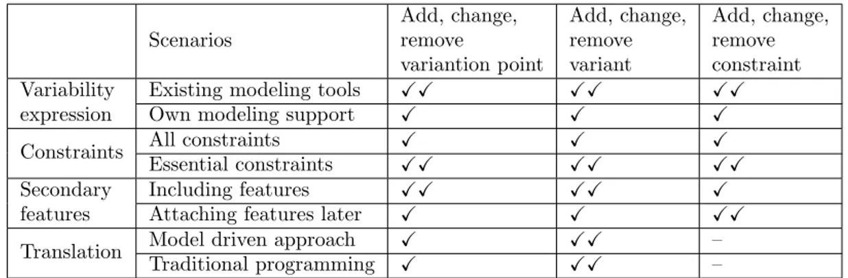
Table 2 summarizes the support of different alternatives of the decisions for the scenarios of evolution in a SPL. Symbols used in the table and their meaning are described below:
• X: the scenario is supported but is time-consuming and requires specific knowledge • XX: the scenario is supported with less effort than in the first case
• – : the scenario is not affected by this option/alternative
Scenarios Add, change, remove variantion point Add, change, remove variant Add, change, remove constraint Variability expression
Existing modeling tools XX XX XX
Own modeling support X X X
Constraints All constraints X X X
Essential constraints XX XX XX
Secondary features
Including features XX XX X
Attaching features later X X XX
Translation Model driven approach X XX –
Traditional programming X XX –
6.
Case Study in a railway transportation domain
This chapter validates the feasibility of the approach proposed in Chapter 5 with an industrial case study provided by Bombardier Transportation. For all of the aspects identified there, we will motivate a choice and explicitly define a process for modeling variability to support automatic generation of configuration files. In addition, an implementation in C#.net is presented for auto-matically generating the files. Thus, benefiting an end to end solution for the problem addressed in this thesis.
First, we will describe the system under study and its requirements in Section 6.1, followed by a thorough explanation of data collection and data analysis process in Section 6.2. To conclude with the validation of the proposed approach in Section 6.3 with the intention to answer our research question in the next chapter.
6.1
High level description of the system under study
At Bombardier Transportation, there exists variability between different projects that are delivered to different customers, as well as variability within a particular project. The Aventra family is a British family of passenger trains designed by Bombardier that will be taken into consideration for this case study. In Aventra there are several types of trains including London Overground train (LOT), East Anglia (EAA) and South West Rail (SWR). These trains have commonalities and variabilities among each other but also can have different configuration within one type. For instance, the number of cars can differ for each type, but also within one type there are versions with a different number of cars. Same with the sort of power supply that can be Dual Voltage(DV), Alternative Current (AC) or Direct Current(DC) among different types of train or within the same type. Most of the variabilities being studied in the data analysis section are on train level (as the ones mentioned above). But there is also some variability on car level, such as car orientation or car position. Each car can be oriented with the same or opposite direction as the leading car. Also, each car can be of a different type. For example, there could be passengers carrying cars and drivers cabin cars and car position in the train changes accordingly.
The infrastructure backbone that controls all the functions in a train is Train Control and Management System (TCMS). TCMS is a complex system with multiple types of software and hardware which is responsible for the vehicle and train control, including onboard communication of other subsystems, passenger information, and entertainment functions. All intelligent units of TCMS, such as controller boards, I/O units and Human Machine Interface (HMIs) are connected and share information via different communication links, such as IP networks. Some of the generic functions in TCMS are:
• Doors control function — this function controls opening and closing of the train doors. • Passenger information function — displaying real-time information to the passenger • Pantograph up/down function — indicating if the pantograph is in contact with the electric
lines.
One of the software units of TCMS is Computer Control Unit (CCU). A CCU unit contains the control program of the train and has a different development for each type of train. This software has an interface that process information for different types of train to change their behaviour.
Given all these facts, the software produced for these type of trains, that have in common the basic functionalities but can differ in some specific functions, can be treated as a product family to take advantage of all benefits of SPL paradigm.
The realization of the different products should be done by means of configuration files. Each product should be described by one configuration file. At Bombardier Transportation case, the configuration file is an XML file that has all features with respective technical values for each train. These files are given as an input to the software interface for determining different aspects of the software. Currently, the management of the configuration files is done manually, being time-consuming and error-prone. In this chapter, we will give an example of how to automate this process.
6.2
Data collection and data analysis
According to Lethbridge et al. [34], we have used the third degree of data collection techniques. All the data that are used for the case study are extracted from the Software Architecture and Design Specification (SAS) of Aventra TCMS Applications.
After carefully reading the document, relevant parts to our problem were extracted and further analyzed. In the limited scope of the thesis, a subset of features has been chosen to demonstrate the feasibility of the approach proposed in Chapter 5. Since the approach is independent of the number or type of features, it can be extended to other kinds of features as well. These features can be categorized as:
• Primary Features — All of the features that categorize the product and combination of which is a configuration that defines one type of product.
• Secondary Features — All of the features that do not explicitly define a product, but have predefined values for each type of product.
With the help of the primary features, we have identified which are the main products that will be derived from the product family. Figure 11 shows the current products. One branch of the tree (from root to leaf) represents one product. Level one of the tree hierarchy describes the possible types of trains that can be: LOT, EAA or SWR. For each type of train, there is shown the possible number of cars is shown. It can be respectively four or five for LOT, five or ten for EAA and SWR. The third level depicts the type of voltage. A permanent linking of two five-car sets composes the consist that has ten cars. Therefore, another branch in the fourth level, which specifies the side of the consist (Side A or B) is needed. This information is important because the two sides have different configurations of cars and functions.
Figure 11: Aventra product family
In the next step, all other features categorized as secondary features, were carefully analyzed with their technical values for each product.
Table 3 describes the configuration parameters in the configuration file. In the first column is shown the name of the parameter. The second column maps the configuration parameter with the corresponding feature(s). Most of the runtime configuration parameters are related one to one to the features of the product line, except the project name parameter, which is related to all primary features. A short description and possible realization for each parameter are presented in the third column. Type of the parameter is shown in the last column. The parameters are inspired by the company data but are not the same to maintain the anonymity of the company’s confidential data.
Parameter name in config. file
Feature name
in feature model Description
Type of value in config.file project name type carNr voltage
The parameter refers to a specific valid customer product It has different integer values for different products: Lotrain 4 cars, Lotrain 5 cars,
East Anglia 5 cars, East Anglia 10 cars, Sowth West 5 cars, Sowth West 10 cars side A or B of 5 car consist)
Integer
high voltage config voltage
The parameter refers to the high voltage
configuration in the consist. It has different integer values that correspond to different high voltage configurations: AC, DC, DV
Integer
max speed maxSpeed
The parameter refers to the maximum speed
that the train can reach. It has different integer values for different values of speed that can be:
unknown, 140kph/87mph, 180kph/111mph, 250kph/155mph
Integer
nr of cars in consist carNr The parameter refers to the number of cars in consist. Integer nr of doors per car doorsPerCar The parameter refers to the number of doors per car. Integer half consist position sideOfConsist
The parameter refers to the side of the 5-car consist. It has a boolean value and is true if the cosist side is ”A” and false if consist side is ”B”
Boolean
type car1 car1type The parameter refers to the type of car 1 in consit.
It has a string value that can be: A, B, C, D, E String type car2 car2type The parameter refers to the type of car 2 in consit.
It has a string value that can be: A, B, C, D, E String type car3 car3type The parameter refers to the type of car 3 in consit.
It has a string value that can be: A, B, C, D, E String type car4 car4type The parameter refers to the type of car 4 in consit.
It has a string value that can be: A, B, C, D, E String type car5 car5type The parameter refers to the type of car 5 in consit.
It has a string value that can be: A, B, C, D, E String orientation car1 car1o
The parameter refers to the orientation of car 1 relative to the leading car. It has an integer value that corresponds to unknown, same, opposite.
Integer
orientation car2 car2o
The parameter refers to the orientation of car 2 relative to the leading car. It has an integer value that corresponds to unknown, same, opposite.
Integer
orientation car3 car3o
The parameter refers to the orientation of car 3 relative to the leading car. It has an integer value that corresponds to unknown, same, opposite.
Integer
orientation car4 car4o
The parameter refers to the orientation of car 4 relative to the leading car. It has an integer value that corresponds to unknown, same, opposite.
Integer
orientation car5 car5o
The parameter refers to the orientation of car 5 relative to the leading car. It has an integer value that corresponds to unknown, same, opposite.
Integer

![Figure 2: SPLE framework (adapted from [2])](https://thumb-eu.123doks.com/thumbv2/5dokorg/4718212.124436/10.892.131.760.219.605/figure-sple-framework-adapted-from.webp)
![Figure 3: Feature model for the mobile phone domain (adapted from [3])](https://thumb-eu.123doks.com/thumbv2/5dokorg/4718212.124436/12.892.161.714.658.932/figure-feature-model-mobile-phone-domain-adapted.webp)
![Figure 4: Four-layer framework of MDE. (adapted from [4])](https://thumb-eu.123doks.com/thumbv2/5dokorg/4718212.124436/14.892.285.605.123.477/figure-layer-framework-mde-adapted.webp)