V¨
aster˚
as, Sweden
Thesis for the Degree of Master of Science in Computer Science with
Specialization in Embedded Systems,
30.0 credits
AUTOMATIC GENERATION OF
NETWORK CONFIGURATION IN
SIMULATED TIME SENSITIVE
NETWORKING (TSN)
APPLICATIONS
Albert Bergstr¨
om
abm13007@student.mdh.se
Examiner: Saad Mubeen
M¨
alardalen University, V¨
aster˚
as, Sweden
Supervisors: Bahar Houtan
M¨
alardalen University, V¨
aster˚
as, Sweden
Mohammad Ashjaei
M¨
alardalen University, V¨
aster˚
as, Sweden
Abstract
The amount of data required to be processed in real-time embedded system is steadily increasing. This has caused industries to search for alternatives for reliable time-sensitive network communi-cation. IEEE set of standards for Time-Sensitive Networking (TSN) is an attractive option for achieving this. It leverages the advantages of IEEE standards for Ethernet, such as high bandwidth and low hardware cost, while introducing deterministic behaviour. Simulation tools are used to facilitate verification and analysis of TSN networks. However, even simulation-assisted design of large complex networks is a challenging process. To alleviate this issue, this thesis investigates how TSN simulation can be improved by automatic generation of network configurations. So far, many different simulation frameworks have been developed in academia. This thesis builds on the OMNeT++ simulation framework and NeSTiNg simulation model. We prototype an automatic TSN configuration tool capable of generating configuration automatically through a graphical user interface (GUI). The purpose of the prototype is to demonstrate the feasibility of automatic con-figuration in TSN and how it eases design complexity. Furthermore, to verify the proposed tool a use case inspired by the vehicle industry is modelled. It is concluded that automatic configuration improves usability in five key areas, such as: (1) facilitating recollection of the network, (2) en-abling automatic configuration, (3) increasing user-friendliness of a TSN simulation platform with a GUI, (4) increasing efficiency and usability of a TSN simulation platform, and (5) minimizing user error. The results gained in this thesis justify the usability of automation and could provide insights for future research and development of TSN simulation tools.
Table of Contents
1. Introduction 1 1.1 Motivation . . . 2 1.2 Problem Formulation . . . 2 1.3 Thesis outline . . . 2 2. Background 3 2.1 Real-time systems . . . 3 2.2 Ethernet . . . 3 2.3 Switched Ethernet . . . 42.4 Ethernet and Real-time . . . 4
2.5 Time Sensitive Networking (TSN) . . . 5
2.5.1 Traffic classes . . . 6 2.5.2 Scheduling mechanisms . . . 6 2.5.3 Frame preemption . . . 6 2.6 OMNeT++ . . . 6 2.6.1 NED . . . 7 2.6.2 INET Framework . . . 7 3. Related Work 8 3.1 Comparison of schedule synthesis methods . . . 8
3.2 Simulating Time-Sensitive Networking . . . 9
4. Method 11 4.1 System Development Research Method . . . 11
5. Design description of the tool 13 5.1 Choice of platform . . . 13 5.2 Component description . . . 14 5.3 Configuration reader . . . 15 5.4 Network parser . . . 15 5.5 Flow GUI . . . 15 5.6 Node GUI . . . 17
5.7 Gate state GUI . . . 17
5.8 Schedule generation . . . 18
5.9 TSN flow extraction . . . 18
6. Network configuration use case 20 6.1 Use Case Description . . . 20
6.2 Modeling of the Use Case with the TSN-configuration tool . . . 22
6.3 End-to-end Timing Analysis of the Use Case . . . 23
6.3.1 Configuration 1 - All gates open with no frame preemption . . . 23
6.3.2 Configuration 2 - All gates open with frame preemption enabled . . . 24
6.3.3 Configuration 3 - Gate schedule with no frame preemption . . . 24
6.3.4 Configuration 4 - Gate schedule with frame preemption enabled . . . 25
6.4 Discussion . . . 25
6.4.1 Improvement area 1 - Recollect of network properties . . . 26
6.4.2 Improvement area 2 - Manual inputs . . . 26
6.4.3 Improvement area 3 - Visual aid . . . 26
6.4.4 Improvement area 4 - Efficiency . . . 26
6.4.5 Improvement area 5 - User error . . . 27
7. Conclusion 28 7.1 Reflection on the research question . . . 28
References 32
Appendix A Installation guidelines 33
1.1 OMNeT++ . . . 33
1.2 NeSTiNg . . . 33
1.3 TSN-configuration tool plug-in . . . 34
Appendix B Using the tool 35 2.1 Preparing the network . . . 35
2.1.1 Notes about the NED . . . 36
2.1.2 INI . . . 36
2.2 Configuration schedules with the tool . . . 36
2.2.1 Loading the files . . . 36
2.2.2 Working with flows . . . 37
2.2.3 Viewing nodes . . . 38
2.2.4 Gate schedule and diagram . . . 39
1.
Introduction
Real-time embedded systems have an essential role in many different industries such as in auto-motive, locomotion and aviation industries. These systems require the ability to process physical and ambient events within a specified time, such as emergency brakes or events based on sensor data, camera, LIDAR and accelerometers. Many of these systems are commonly implemented as distributed systems, connecting various sensors, actuators and nodes. For these systems, it is important to determine end-to-end delay from the point the event has been sensed to the point the system is ready to react to the event. However, in most traditional networks the end-to-end delay of a packet is affected by other traffic on the network and, during heavy traffic loads, can be indefinitely blocked. As a result, network delay and delay variation (jitter) in real-time communi-cation must be deterministically bounded [1].
Due to this need for reliable time-sensitive network communication, many different approaches have been suggested. Controller Area Network (CAN) [2] has been a communication protocol well suited for real-time systems but with some drawbacks such as the trade-off between signal rate and network length. For instance, if a cable length of 100 m is required, then the network will be limited to a signal rate of approximately 0.5 Mbps to be reliable [2]. Ethernet is an attractive alternative to CAN, as it has a considerable bandwidth and low adoption cost. These are important properties as many real-time systems today face increasing communication needs in terms of network capacity to process and transfer a considerable amount of data (such as raw camera data, map data and high-resolution displays). However, Ethernet has some innate properties which made it infeasible for real-time systems. For instance, it is impossible to guarantee a bounded message transmission time with conventional Ethernet [3].
As a result, the Institute of Electrical and Electronics Engineers (IEEE) developed the Time-sensitive networking (TSN) standards. TSN standards are extensions of the IEEE Ethernet stan-dards to support high-bandwidth, mixed-criticality, low-latency real-time communication and are promising solutions to be applied in various real-time domains. Several scheduling algorithms are available in TSN for controlling traffic flow, such as time-triggered gating, priority scheduling, credit-based shaping as well as other supporting mechanisms like frame preemption and frame du-plication. For example, TSN provides different traffic classes, including time-triggered (TT), Audio Video Bridging (AVB) and Best Effort (BE), to handle mixed-criticality communication. Many of the TSN mechanisms can be deployed simultaneously (for example combining credit-based shap-ing on a queue with time-triggered gatshap-ing and frame preemption) to create intricate behaviour, resulting in a complex network which can be difficult to analyze [4]. As the network grows, the complexity of the analysis also grows. Therefore, configuring, simulation and interpretation of the network in terms of behaviour, timing and scheduling becomes a challenging task. OMNeT++ is a popular discrete event simulation framework used in scientific as well as in industrial settings [5]. The framework consists of many different components, including a simulation kernel library which several simulation tools are based on [6]. One of the extensions to OMNeT++, called Network Simulator for Time-Sensitive Networking (NeSTiNg) [4], models several TSN mechanisms includ-ing the time-triggered schedulinclud-ing mechanism and frame preemption. However, although existinclud-ing simulation models such as NeSTiNg have implemented the fundamental characteristics of the IEEE TSN standard, they still have some limitations when attempting to simulate larger networks. For example, in all of the existing academic simulators creating or modifying network configurations, to define TSN traffic of the network, involves working with raw text files. As such, designing complex networks in this simulators can be challenging for the designers. Another related issue is the trace-ability of errors made during the configuration of the simulated network. With several different files requiring modification, tracing errors during the process is challenging. As this field of research is significant for many industries which rely on real-time systems, the main purpose of this thesis is to facilitate the analysis and use of TSN networks by exploring different approaches to automatically generate TSN networks configurations. The thesis will also examine approaches to automate and enhance simulation tools to deliver more meaningful and understandable visualization of results.
1.1
Motivation
Design and analysis of dependable real-time networks based on TSN standards is a complex process. Simulation frameworks have been developed for this purpose, alleviating some of the difficulties with network analysis in TSN. Moreover, careful configuration of the complex simulated TSN net-work is also essential.
In TSN, the critical traffic schedule must be planned beforehand. For network simulations, several properties can be configured including traffic schedule for each node, type of nodes, TSN switch parameters and the traffic class. To allow several different types of traffic to coexist in the same network, TSN includes specifications for traffic classes. Each traffic class has a unique priority and is isolated from the other traffic classes to prevent interference. The purpose of this is to accommo-date the specific requirements of timing and bandwidth of each traffic class, ensuring deterministic behaviour.
Planning the TSN configuration depends on the properties of the network including transmis-sion delays, processing delays, package sizes as well as the individual deadlines of tasks. As a result, creating these configurations by hand is a challenging task and becomes more infeasible as the size of the networks increases. Complex real-time networks can have many different kinds of traffic, each with individual requirements of worst-case response time, packet frequency and size of payload. The more data that needs to be relayed between senders and receivers, the more problem-atic it is to configure. Additionally, manual configuration of nodes in the network to comply with timing requirements is time-consuming, especially when considering changes might be required after analysis indicates an issue with the current configuration.
The focus of this thesis is to explore the possibility of extending an existing simulation frame-work, OMNeT++, with an automatic process to facilitate the creation and modification of TSN network configurations.
1.2
Problem Formulation
The main goal of this master thesis is to investigate automatic configurations of TSN networks by analyzing TSN simulations tools. The thesis aims at providing an answer to the following research question:
• How can TSN configuration be automated to improve the usability of the TSN simulation tools?
To investigate this research question, existing literature will be reviewed. Based on the knowledge gained through this process, a tool will be implemented which can generate network configura-tions for TSN. A use case inspired by the vehicle industry is modelled with the prototype tool to demonstrate its usability. For the use case, the simulation framework OMNeT++ will be the tar-geted platform to be integrated with the tool, using existing network descriptions in the framework along with user-defined network performance requirements to generate configurations. OMNeT++ is considerably modular and popular with the scientific community, which makes it suitable as the targeted platform for the use case. The purpose of the tool is to validate the proposed approach to automatic configuration of TSN and examine how it improves usability.
1.3
Thesis outline
Section 2. describes some relevant background, including main terms and concepts, which are required to know for the thesis. Section 3. presents the related work done in TSN simulation and automation. Section 4. present the approach employed and explains how it was carried out. Section 5. described the configuration tools design, examining and motivation design decision. Section 6. presents the modelled use case using the tool to demonstrate its usability. The results are presented along with a discussion of the usability improvements gained through automatic configuration. Section 7. presents the conclusions reached in this work as well as suggestions on potential future work.
2.
Background
Computer Networks is a core part of Information Technology (IT), allowing computational devices to communicate and share data. Ethernet is the most popular medium for networks, due to low cost, scalability and high bandwidth. TSN is built on Ethernet, both developed by the IEEE through the IEEE 802.3 and IEEE 802.1 respectively. TSN leverages the advantages of Ethernet such as scalability and bandwidth while providing deterministic behaviour necessary for real-time systems. Several simulation frameworks are available for simulating network behaviour, such as ROSS[7], J-Sim[8] and TraceR[9]. For this work we have chosen the simulation framework OM-NeT++ as the targeted platform for the automatic TSN configurations tool, as it supports TSN mechanisms through NeSTiNg.
In the following subsections, the concepts of Ethernet, real-time systems, time-sensitive networking as well as OMNeT++ will be described in detail.
2.1
Real-time systems
Real-time systems are the foundation of many modern embedded systems, such as vehicle control systems, industrial control systems and electric power system. A real-time system is a system which not only dependent on the logical correctness of its performance but also time-bound. Tasks must be done within their defined real-time constraint. Real-time systems are designed for predictability to ensure that certain tasks are carried out within a maximum allowable amount of real-time. For example, as real-time systems have to handle several different tasks simultaneously, tasks in real-time systems must be scheduled when to executed to ensure time constraints are met. For critical systems, it should be possible to demonstrate that the schedule can fulfil all real-time constraints (with some assumptions of system the specifications). Not fulfilling time constraints in a real-time system can have varying consequences, from the degradation of service to fatal system failure. Time-constraints in real-time systems can be divided into three categories based on the consequences of a missed deadline: hard, firm or soft [10].
• Hard real-time constraint: The result of not meeting the deadline would have catastrophic consequences and are non-tolerable, typically used for periodic tasks. Examples of this are airbags, vehicle control and medical equipment such as Electrocardiogram (ECG/EKG) mon-itors.
• Firm real-time constraint: Missing a deadline is tolerable. However, If the process is not carried out before the deadline, the result has zero utility, and the task should be aborted. Database transaction for banks, ticket sites and betting sites usually operate with firm real-time constraints.
• Soft real-time constraints: Occasional deadline misses are tolerable, but could negatively impact the Quality of Service (QoS) as the utility of the result decreases after the deadline has passed. Video streaming, consumer electronics, and map updates are some example of soft real-time constraints.
Many embedded systems are also implemented as real-time systems. In a real-time embedded system, the embedded components must also be considered. For instance, when components must communicate over a network, the end-to-end delay of the network must be bound to guarantee critical messages can be transferred within the real-time constraint.
2.2
Ethernet
Ethernet includes a collection of network technologies standards for communication in Local Area Networks (LAN). The Open System Interconnection (OSI) standard for computer communication consists of seven layers, physical, data link, network, transport, session, presentation and applica-tion layer. Ethernet encompasses both the physical and data link layers from the OSI model[11]. Several variations of physical mediums and ranges are included in the Ethernet standards for the physical layer, such as coaxial, fibre-optic and twisted pair cable. Since the initial development
of Ethernet in 1976 by XEROX Palo Alto Research Centre (PARC) [12], Ethernet has steadily increased the serial transmission bit rates and serves for handling communication in applications that are based on ever-growing data [13]. In 2017 bit rates of 200Gbit/s and 400Gbit/s were intro-duced to the IEEE standard for Ethernet [14]. The data link layer of Ethernet is made up of two sublayers, the Logical Link Control (LLC) and Medium Access Control (MAC) layer. MAC is re-sponsible for the hardware which has access to the transmission medium. Every Ethernet interface is given a unique 48-bit MAC address to be identified in the network. The LLC is responsible for error-correction and controlling the link between nodes, acting as an interface between the upper network layer (OSI layer 3) and the MAC layer.
Ethernet networks were initially designed to use a shared medium for all connected nodes, similar to how radio systems and CAN operate, and support several different kinds of network topology. Token bus networks were one of the early arbitration mechanisms developed1, where one token was passed around each node in the network and only the node with the token was allowed to transmit. However, token bus networks were difficult to set up, caused issues when the number of nodes on a network changed. Ethernet is based on an arbitration mechanic called Carrier Sense Multiple Access/Collision Detection (CSMA/CD). With CSMA/CD every node in the network listen to a common medium, generally through an Ethernet hub which repeats incoming traffic to every other port, to sense if the medium is idle (Carrier Sense). If no transmission is detected, each node is allowed to transmit onto the medium (Multiple Access). While transmitting, the nodes monitor the medium to detect collisions (Collision Detection). In the case a collision is detected, the nodes send out a jamming signal to indicate for every receiver that a collision is detected and then they wait a random amount of time before trying to transmit again. If another collision happens after the waiting period, the period is increased exponentially until either the transmission succeeds or the transmission node reaches the 16th attempt which will cause the node to abort retransmission [15]. The end-to-end delay of conventional Ethernet is unbound, as in theory transmissions can be perpetually blocked due to network congestion.
2.3
Switched Ethernet
Conventional Ethernet networks operate by broadcasting the message from a source node to all connected nodes in the network, with no regard of destination. This means that only one node can transmit messages at any given time. As the number of nodes on the network increases, the conventional Ethernet method yields exponentially worse efficiency as more nodes has to wait until they can transmit. Switched Ethernet addresses this issue by only sending traffic from sources to its destinations. While an Ethernet hub simply repeats traffic to every connected port, an Ether-net switch generates a MAC table containing the MAC addresses of every connected interface to manage where messages should be sent. This allows Ethernet switches to have multiple concur-rent transmissions in the network, greatly increasing switches efficiency. With switched Ethernet, full-duplex is also possible, allowing nodes in the network to receive traffic while simultaneously transmitting. Switched Ethernet makes up most of modern LAN, as it is considerably more effi-cient. The only disadvantage with switched Ethernet is the slight latency introduced by performing MAC table lookup to determine the message receiver, which is negligible. As the Ethernet switch can control the flow of traffic on the network, end-to-end delays throughout networks can be bound. This is the core principle of TSN, controlling the flow of traffic at endpoints to create deterministic behaviour.
2.4
Ethernet and Real-time
As technology continues to advance, more and more data will be required to be transmitted over real-time systems. As a result, Ethernet has become an attractive option for many real-time sys-tems with its high bandwidth, scalability and low cost. However, standard Ethernet is not suitable for real-time systems as it is comprised of several mechanisms which prevent data transmissions from being guaranteed and instead operating using BE. Due to the lack of deterministic behaviour,
several standards have been proposed based on Ethernet to solve the problem of unpredictabil-ity for standard Ethernet-based communication. Protocols based on Ethernet do not have any innate support for real-time requirements, such as Transmission Control Protocol (TCP), User Datagram Protocol (UDP) and Internet Protocol (IP). Therefore, real-time Ethernet solutions typically introduce special transport protocols focused on delivering low latency and deterministic delay guarantee [16]. Some examples of the real-time communication standards based on Ether-net are: EtherEther-net Powerlink2, TCnet3, CC-Link IE Field4, EtherNet/IP5, SERCOS III6, Profinet7, TTEthernet8. However, a considerable disadvantage with these specialized approaches is that they are incompatible with other networking technologies. Solving this issue is one of the goals with the TSN standard.
2.5
Time Sensitive Networking (TSN)
TSN, developed by the IEEE 802.1 TSN Task Group, is a collection of IEEE 802.1Q standards which introduce deterministic, real-time communication over Ethernet. TSN works at the data link layer of OSI, ensuring that information transmitted between two points in a network arrives within a fixed and predictable amount of time.
The IEEE 802.1 AVB was initial created 2007 for the purpose of developing AVB, which would replace audio, High-Definition Multimedia Interface (HDMI) and other cables by standardizing Audio Video (AV) transfer over Ethernet [17]. The AVB Task Group developed several standards for creating ad hoc networks for streaming AV with low jitter and bound latency. The standards included:
• 802.1AS: ”Timing and Synchronization for Time-Sensitive Applications” which described synchronization protocols and procedures,
• 802.1BA: ”AVB Systems” which defined components and preparations necessary for building networks supporting time-sensitive AV data streams,
• 802.1Qat: ”Stream Reservation Protocol” which reserves bandwidth by establishing a path between senders and receivers through the network,
• 802.1Qav: ”Forwarding and Queuing for Time-Sensitive Streams” which describes timing-aware queue draining algorithms.
In 2012, the IEEE 802.1 AVB Task Group was renamed to the TSN Task Group and begun working on a number of TSN standards.
Time-critical communication between end devices in TSN is commonly expressed with the term ”TSN flows”. Each TSN flow is unidirectional, going from one source end device to destination end device with a unique identification and time requirement. Bridges (also referred to as switches) transmits and receives frames for a TSN flow based on a time schedule. To operate correctly, all bridges and end devices must first be time synchronized to ensure the time schedule is followed correctly throughout the network. The IEEE 802.1AS-rev standard, a redesign of 802.1AS, spec-ifies the protocol for establishing and maintaining time synchronization between network devices. Several queuing algorithms are specified for TSN to provide bounded latency and prevent con-gestion loss. Concon-gestion loss occurs when buffers in a node are overflowed with packets. TSN networks pace the transmission of packages so the amount of traffic never exceeds the capability of buffers and can be delivered within a bounded latency. TSN also offers methods for increasing the reliability of packet delivery. By sending copies of data over several paths in the network, TSN can avoid packet loss caused by equipment failure.
2https://www.ethernet-powerlink.org/ 3https://www.toshiba.co.jp/sis/en/seigyo/tcnet/technology.htm 4https://www.cc-link.org/en/cclink/cclinkie/cclinkie_f.html 5https://www.odva.org/Technology-Standards/EtherNet-IP/Overview 6https://www.sercos.org/technology/what-is-sercos/ 7https://us.profinet.com/technology/profinet/ 8https://www.tttech.com/technologies/time-triggered-ethernet/
A significant advantage with TSN, compared to other real-time Ethernet solutions, is that it enables different kinds of traffic to be consolidated into one single network. Unless TSN flows demands an extensive amount of the bandwidth from a network link, devices requiring BE traffic can still as operate as normal. This means that critical and non-critical traffic can share the same infrastructure, reducing cost.
2.5.1 Traffic classes
Traffic classes in TSN are encoded in the data link frame and represented by a three-bit priority code point (PCP). TSN uses eight traffic classes to prioritize different types of data traffic based on the QoS required. Although not mandatory, IEEE provides some suggestions for each traffic types [18, pp. 1711-1712] represented by the eight combinations of PCP. Each TSN bridge can queue up to eight different traffic classes on every port. When queues are allowed to transmitted is controlled by so-called gates, which can either be open or closed. If two or more gates are open at the same time, the queue with the highest priority is drained first.
2.5.2 Scheduling mechanisms
The IEEE 802.1Qbv standard defines the scheduling and transmission of frames for bridges and endpoints for time-sensitive networks. The Time-Aware Shaper (TAS), specified in the 802.1Qbv standard, is responsible for determining when different traffic classes should be allowed to transmit on a network and is an essential feature of TSN. Based on time-triggered scheduling, TAS schedules consist of equal discrete time-slots. Each slot specifies which gate should be open or closed at that specific time. The schedule is represented in a list, called Gate Control List (GCL), which contains the time-slot entries and the associated configuration of gate states (GS). During operation, the list is iterated through with gates opening and closing according to the entry. When the last entry is reached, the schedule returns to the first entry and continues.
Credit-Based Shaper, defined in 802.1Qav, is another scheduling mechanism which can be imple-mented together with TAS. The Credit-Based Shaper distributes the transmission for two traffic classes to even-out sudden increases in traffic and is suitable for performing AVB. With the Credit-Based Shaper, queues build up credit when packets are waiting in the queue and spend credit to send packages. While useful for reducing delays for AVB, the mechanism is unsuitable for real-time traffic which requires deterministic behaviour.
2.5.3 Frame preemption
The IEEE 802.1Qbu standard defines a class of service for time-critical frames to preempt the transmission of non-time critical frames. In standard Ethernet, once a frame has started being processed, it will continue being processed until it has finished being transmitted. This is an issue for time-sensitive networks, as a time-critical frame that just arrived will have to wait until the non-time critical frame has finished transmission [19]. As a result, the transmission latency for the time-critical frame is increased unexpectedly, and it could cause issues with the time-scheduled traffic in the network. The amendment was introduced to address this issue, by providing a mechanism for interrupting non-time critical frame mid-transmission when a time-critical frame arrives. Once the time-critical frame has been processed, the non-time critical frame resumes the transmission. A requirement for frame preemption is that both the transmitting and receiving devices has support for this mechanism.
2.6
OMNeT++
OMNeT++ is an abbreviation of Objective Modular Network Testbed in C++ and is a discrete event simulation platform, primarily used for constructing simulations of networks [5]. While OM-NeT++ itself is not a network simulator, it provides an extensive simulation framework and library for modelling network components. OMNeT++ is open-source and free to use for non-commercial
purposes such as research and teaching. As a result, the platform has gained widespread pop-ularity in the scientific community with several simulation model and frameworks being based in OMNeT++. OMNeT++ models are built using nodes and messages. Components are im-plemented using the provided C++ library and can be combined to model complex behaviour. OMNeT++ also provides an Integrated Development Environment (IDE) based on the Eclipse platform with several features such as C++ editing, result analyze and file editor for configuring simulation models execution.
2.6.1 NED
Network topologies in OMNeT++ are defined through NED description language. The Integrated Development Environment provides a Graphical User Interface (GUI) for creating and editing the network structure with modules and channels.
2.6.2 INET Framework
INET9 Framework is a comprehensive open-source model library created for OMNeT++. INET contains several models for simulating protocols, including Ethernet, Transmission Control Pro-tocol (TCP), User Datagram ProPro-tocol (UDP), IP version 4 (IPv4) and is especially useful for studying new protocols in various networks including wired, wireless and mobile networks. Be-cause of this, many researchers working in OMNeT++ utilize INET modules and components as a base for their models.
3.
Related Work
As TSN gained more popularity, more focus has been placed on making the implementation of TSN networks easier. Many researchers have presented different TSN models which focus on various aspects of TSN. Automatic synthesizing of TSN schedules which can fulfil real-time constraints is also a prominent area of research which can be approached with various methodologies. The tool presented in this thesis does not include any form of automatic schedule synthesizing. However, it is still beneficial to examine work relate to schedule synthesizing as generated schedules could be used as input for the automatic configuration. Section 3.1 presents some of the work investigating schedule synthesis. Section 3.2 presents research done in the field of TSN network simulation.
3.1
Comparison of schedule synthesis methods
Researchers have proposed several different approaches to synthesize schedules in networks with real-time constraints. Nigam et al. presented a tool, TSNsched [20], which can automatically gen-erate a TSN schedule. The tool uses a topology of a network and a Satisfiability Modulo Theories (SMT) solver called Z3 [21] to generate schedules for each TSN switch in the network. This tool is the first openly available tool for generating TSN schedules, according to the authors. An open-source implementation of TSNched is available online10based on the theoretical work of the paper. Serna et al. addressed the scheduling problem of TSN by examining what information is re-quired from the network to derive scheduling constraints [22]. Based on the key parameters and scheduling constraints, a graph-based approach for computing static schedules was presented. In this approach, a generalized network model is first extracted and modelled as a directed graph. Then, scheduling constraints are defined which will guarantee the correct temporal behaviour. In this work, the authors defined two types of scheduling constraints: Basic Deterministic Ethernet Constraints which are constraints defined for one single frame and 802.1Qbv Constraints which defines constraints for specified traffic queues which encompassing all frames of the same priority. To determine if the current set of scheduling constraint is schedulable, the authors used an SMT solver similar to the previous work. SMT is suitable for solving constraint-satisfaction problems [23,24]. The goal of the solver was to determine offset and queue priority for each frame in the network. However, some issues were presented by the authors. As the task of finding a feasible time-triggered schedule is an NP-complete problem [22], the approach had poor scalability. As the size of a network is increased, the computational time required to synthesis a schedule grows exponentially. To alleviate this issue, a modified implementation of SMT was used, which included an incremental backtracking algorithm to eliminates unfeasible schedules early in the process [25]. The second issue is a lack of possibility to optimize the result for a specific property, as SMT will only give the first valid result reached other of many potential solutions, provided a valid result exists. To address this issue, an approach called Optimization Modulo Theories (OMT) was implemented. OMT is an emerging field of research [26]. It functions as an augmented SMT solver, solving constraint-based problems while optimizing for specified goals such as minimizing end-to-end latency or number of used queues.
Serna et al. continued their work on synthesizing GCL schedules in [27] by presenting a novel approach which formulates arrays to express a system of constraints. This work is the first, ac-cording to the authors, that addresses the scheduling problem of windows directly. In this approach, window intervals are computed through these constraints and are mapped to entries in the GCL schedule. The authors compared their window-based synthesis method with the same constraints as their previous work [22] which used a synthesis method based on frames instead of windows. The window-based synthesis was able to reduce the amount of gate open events by scheduling several frames in one window, although this is done after the generation of a schedule and thus not guaranteed due to hardware limits.
Farzaneh et al. present another approach to schedule synthesis in their graphic modelling tool which automatically synthesis schedules for TSN network [28]. Their work applies SMT,
oriented modelling and logic programming to automate the scheduling of TT traffic. The tool consists of a graphical editor where the users can construct a model of their network. The model is based on the Eclipse Modeling Framework and uses two types of nodes, switches and end-stations, with connected links. Logic programming is then used to transform the model into a network knowledge base. The authors use their network query tool to produce queries which are used to define the schedule constraints. The authors demonstrated the tool by modelling a network of their previous work [29], proving the tool’s capability of synthesizing schedules for schedulable networks. An interesting feature of the tool was that it allowed non-schedulable network models to be provided. In these cases, the tool would provide helpful feedback to clarify issues in the model, by indicating unfulfillable conditions and which stream they belong to.
In summary, the research area of schedule synthesis for TSN is still developing as the major-ity of research was done in the last five years. Most approaches utilized an SMT solver such as Z3 and expressed the network topology with a directed graph or object-oriented modelling. The goal of this thesis is to facilitate configuration of TSN networks in OMNeT++. While interacting with a human designer directly is the approach mainly focused on in this thesis, this could also be done through an automatic schedule generator. As the tools presented in this section are external and not integrated with any specific development environment, their outputs could be used directly by the configuration tool. TSNsched in particle, is a compelling option as the tool is publicly available and outputs useful statistics such as total execution time, average latency and average jitter. These different approaches of synthesizing schedule also incorporate some helpful features, including the ability to indicate issues in a model and optimizing for specific properties like end-to-end latency, which could further enhance usability.
3.2
Simulating Time-Sensitive Networking
Jiang et al. presented a simulation model for TSN that was developed using a module-based design method based on OMNeT++ [30]. The simulation model consisted of four modules: Configura-tion, TAS, Queue and Transmission. The Configuration module was responsible for providing TAS with important parameters for how the TAS would operate, including gate state, time interval and length of the GCL. The TAS operated the gates based on the configuration module, controlling the GS. Each GS was represented with an 8-bit value, following the traffic class representation defined in the IEEE 802.1Q standard. The Queue module handled queue priority for each queue, caching traffic as it arrives and transmitting during specific time-slots defined in the GCL. Each traffic class was assigned a corresponding priority queue. The Queue module was based on the CoRE4INET-Framework. The Transmission modules simulated the physical media using the INET-framework, modelling the traffic flows behaviour through the network. A timer was used to establish time-instants, which TAS uses to operate the GS. The model was validated using numerical results from a real-world TSN testbed compared with numerical results obtained from the simulation. The comparison showed that the differences between simulation and testbed were insignificant. The authors expressed a need for bridging simulation nodes with real devices to create and evaluate TSN on a larger scale. This work gives useful insights into how the different mechanisms of TSN can be implemented in a simulation environment.
In their previous work, Jiang et al. developed a TSN simulation model for TSN-enabled switches [6]. Compared to their previous work, which modelled a complete TSN network including end devices with TSN functionality, this study was concentrate on simulating the behaviour of TSN switches. The purpose of the study was to present a TSN simulation model for verifying real-time networks with multiple classes of traffic. Similarly to the author’s previous work, OMNeT++, INET and CoRE4INET were used to develop the simulation model. Along with the simulated TSN-enabled switch, the authors also presented a method for synthesizing GCL schedules based on network topology and timing requirements. In this method, the switch cycles through three time-triggered transmission modes. The first transmission mode (Protected Window) only allows TT traffic to transmit. The second mode (Unprotected Window) occurs after the first transmission mode period has ended and will allow all other classes of traffic to transmits. Lastly, the third transmission mode (Guard Band) stops all transmissions to allow any transmission started in the
previous transmission mode to finish, ensuring the channel is idle when TT traffic continues to transmit. To employ this method, transmission periods for the three transmission modes must first be calculated using formulas provided in the paper. The simulation model was evaluated using two simulated switches, six end devices and three flows of TT, AVB and BE traffic. The authors verified that the model could guarantee bound end-to-end latency for TT traffic without being affected by BE traffic.
Another notable example of TSN simulation framework is NeSTiNg [4]. Presented by Falk et al. NeSTiNg is a collection of extensions for the OMNeT++ and INET framework, made to fa-cilitate simulation of TSN networks. Due to the several overlaying mechanisms TSN encompass, it is difficult to analyze network behaviours using formal network analysis. Therefore, the authors developed this simulation framework to ease evaluations of TSN networks. Several TSN features are provided in NeSTiNg, including time synchronization, preemptable frames by ST traffic, time-aware and credit-based shaping. NeSTiNg is available online11 for use in research and is used in this thesis to modelling various TSN mechanism when evaluating the automatically configure tool. In summary, as these researchers focused on simulating TSN, most of them only studied how the hard real-time traffic behaved. They commonly limited the models to a small subset of TSN mechanisms. Lastly, the majority of presented implementations were not made publicly available by the authors, with the exception of NeSTiNg. This thesis examines automatic TSN configu-ration through the NeSTiNg simulation platform. As such, this thesis will extend the NeSTiNg implementation by introducing automatic network configuration to the framework.
4.
Method
The focus of this thesis is developing new approaches to automatically configuring TSN simulations.
4.1
System Development Research Method
The research approach in the thesis is based on the ”System Development Method” presented by T. Purdin, M. Chen and J. Nunamaker in [31], a multi-methodological approach to conduct re-search in the field of information systems. The several steps of the rere-search process are outlined in Figure 1. This approach is suitable when the research question can not be answered with empirical testing or mathematical proofs.
Analyze and design the system Construct a conceptual framework
Develop a system architecture
Build the (prototype) system
Observe and evaluate the system
Figure 1: The process of System Development Research [31]
The research consists of five stages: literature review, review of existing simulation tools, design of software architecture, implementation and evaluation. Figure 2 shows how the study has been performed. To investigate the process of automatic generation on simulated TSN network, a state
Literature
review Design Implementation Evaluation
Review of existing simulation tools
of the art study was performed on the existing simulation tools currently used for TSN. Different properties of each tool were examined, such as features and limitations, to provide insight into the workflow of TSN network simulation.
A major part of the thesis was investigating the process of automatically configuring a simu-lated TSN network. Before any implementation was performed, a detailed description of how the automating process would be performed was made along with documentation on the software architecture of the tool. The tool itself is based on the OMNeT++ and NeSTiNg framework, im-plemented as a proof of concept. The primary goal of the tool was to act as an interface between raw configuration text files, the simulation and end user. Using a GUI, the tool is able to generate configurations based on user specifications. It is also able to load existing configurations to allow modifications to be made.
Lastly, in order to validate the usability of the tool, an automotive application use case was mod-elled and configured using the tool. The use case included one network model and four different configurations of TSN schedules. The simulated performance of each configuration is analyzed and compared.
The work carried out in this thesis can be summarized in the following steps: • Literature review
• Study and review the existing simulation tools for TSN.
• Investigation on how to automatically configure a simulated TSN network. • Design software architecture of the tool.
• Develop an automated tool to generate TSN configuration using a GUI. • Configure a use case with the configuration tool to validate its usability.
5.
Design description of the tool
In this section, the design of the configuration tools is presented, focusing on the high-level design, and we discuss different approaches to the problem. This section includes some of the critical decisions were made during the design process, the broad design of the tool as well as some of the challenges faced during the design process.
The primary goal of the tool is to elevate the process of simulating TSN networks, by automating the configuration process and providing easily readable information about the TSN flows, such as their path, priority and period, back to the user. To achieve this, the tool has to interact with the user via a GUI and connect to the network simulator OMNeT++ to access the network topology and node addresses. Lastly, the tool generates the schedule and routing files which are required by NeSTiNg to perform the TSN simulation. Figure 3 shows the expected simulation workflow, after the introduction of the configuration tool. The end user creates the network topology (NED), configuration and input data (INI) for the simulation in OMNeT++ and the schedule in the con-figuration tool. The tool uses the network topology and node addresses in OMNeT++ to generate the configuration files. The files are read by NeSTiNg in OMNeT++ which simulates the TSN network and presents the results back to the end user.
Figure 3: The interactions within the TSN simulation workflow
For a more comprehensive description of how to use the tool as well as more details on the software components, please refer to the user documentation in appendix A and B as well as the openly accessible repository12.
5.1
Choice of platform
One of the first design decisions considered was the platform the tool would be implemented on. Creating a stand-alone application was initially considered, as this would offer great flexibility in how the implementation would be carried out along with making the tool easily adaptable to other simulation software and TSN frameworks. The other alternative was to develop the tool as a plug-in for OMNeT++. The OMNeT++ IDE is based on the Eclipse platform, which is an extensible, Java-based framework. Eclipse allows extensions (called plug-ins) to be written in the Java language and added to an existing Eclipse installation, extending it with new functionality by contributing various user interface elements into the platform user interface. As an OMNeT++ specific plug-in, the tool would have access to the OMNeT++ API provided proving many useful functions such as browsing, accessing and even modifying the data structures used by OMNeT++,
including INI and NED files. Another advantage with this approach is that the tool can be used in tandem with OMNeT++, accessing currently open projects and adding functionality directly to the IDE.
While initially, the intent was to use a stand-alone implementation, it was ultimately decided that the tool would be most suited as an OMNeT++ specific plug-in. While this would limit the available resources to employ with the tool, partially the graphic representation, the ability to uti-lize OMNeT++ specific API functions and more directly interact with the workflow was deemed to be more important.
5.2
Component description
To ensure the tool would fulfil the purpose of facilitating working with TSN network configuration, a set of requirements were formulated. The requirements to guide the software architecture design. The following requirements were specified:
• The tool should be able to read all necessary files containing network topology and settings. • The tool should allow existing configuration to be examined and modified.
• Users should be able to add, modify and remove TSN flows using a GUI. • Switch gate schedules should be configurable with a GUI.
• Statistics of individual TSN flows, including packages received and end-to-end timing, should be extract-able through the tool.
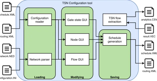
The software implementation was divided into several components, based on the requirements of the tool. Figure 4 shows the derived components and the information flow between them. The tool
TSN Configuration tool
Modifying Saving
Loading
Configuration
reader Gate state GUI
Node GUI Schedule
generation TSN flow extraction Flow GUI Network parser schedule.XML routing.XML network.NED configuration.INI schedule.XML routing.XML result.VEC analytics.CSV
Figure 4: The software components of the tool
operates in three stages: First, loading all the necessary files and configuration. Then, presenting the GUI allowing the user to modifying the network configuration as needed. Finally, the required schedule and routing files are generated by the tool. However, in addition to these three states, one noticeable component exists outside this flow. OMNeT++ does not have any innate function for extract analytic data for specific TSN flows at the time of this writing. As such, the ”TSN flow extract” component will also be added to the tool to further help working with simulated TSN networks using OMNeT++ and NeSTiNg.
5.3
Configuration reader
To have simulated TSN traffic using NeSTiNg in OMNeT++, the network must be provided with two Extensible Markup Language (XML) files containing the network configuration. One file spec-ifies the TSN flows that should be present in the network, including the source node, a destination address, size of the package, transmission cycle and the priority code/traffic class. The other file specifies the static forwarding of packages for switches, meaning which port each switch in the network should forward traffic to based on the package destination address.
The configuration reader is responsible for receiving the existing configuration supplied by the user, parsing the content to extract all TSN flows present and forwarding the flows to the GUI. While reading existing configuration is not a strictly necessary feature for the tool to generate new schedule configurations, omitting the ability to reuse existing configuration would be inconvenient. To illustrate this, consider the following two scenarios:
1. The user wants to make a small modification to an existing flow, such as changing the size of the transmission.
2. A new TSN node has been added to an existing large network and the user wants to add a TSN flow from this node.
In both of these scenarios, the user is attempting to make a change to schedule limited to one flow. However, without the ability to read existing configurations, the user would be required to recreate the configuration before proceeding. It would be unreasonable to expect the user to redo the complete network configuration whenever one of these scenarios arises. Fortunately, several libraries are provided in Java for parsing XML files.
5.4
Network parser
When performing simulations in OMNeT++, a NED and INI file must always be provided. INI files contain model parameter assignments, input data and other related settings, including the MAC addresses for every node. NED files contain component declarations and topology descrip-tions of networks. When configuration the TSN schedule, both files are necessary.
The Network parser is responsible for determining what nodes are present in the network and how they are connected using the NED file, while it extracts nodes specific properties through the INI file. However, one challenge with this task is that OMNeT++ supports the use of wildcards in INI files. Wildcard characters are tokens which represent some number of characters. For the INI file wildcards can be used to reference several different nodes or gates within one line. This means that node names in the NED file might only be partially found in the INI file. As a result, simply searching for the complete node name would not work.
This could have been addressed in a few different ways. For instance, as the tool is a proto-type, it could be specified that using wildcards with the tool is prohibited. Another way would be to go through each line in the INI file and search for any partial matches with each node in the NED file. Lastly, using the OMNeT++ Java API to parse the INI file together with NED. While the API function is not design for this purpose, as it reads all NED files accessible in the project and is somewhat slower than the other approaches, this was still deemed the most suitable approach for the Network Parser. Prohibiting wildcards would make the tool incompatible with most INI files and naively searching for partial matches would potentially neglect OMNeT++ specific features such as comment lines. The selected approach also has the advantage of likely working with any potential changes in newer releases of OMNeT++.
5.5
Flow GUI
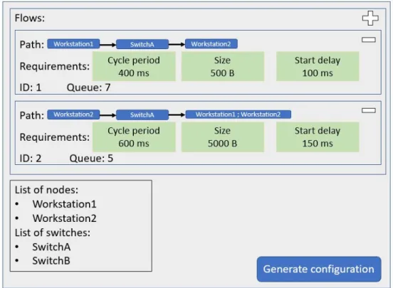
An essential part of the tool is the presentation of TSN flows. The Flow GUI is responsible for presenting TSN flows to the user. Each TSN flow is displayed comprehensibly with related properties. The user is also allowed to add, modified or removed TSN flow at will. The presented
properties for each TSN flow is based on the requirements of configuration files by NeSTiNg and are as follows:
• Cycle - The period cycle time.
• Start - Offset for when packages should be sent, relative to the cycle. • Queue - The priority code for packages in the flow.
• Size - The amount of data that should be transmitted.
• Path - The source, destination and all nodes visited along the way.
While almost all of these properties are easy to read and present, one exception is the path. The explicit path is not specified for each flow. Rather, only the source and destination for each flow are explicitly specified. The switches within the path between the source and destination are listed in a separate static forwarding table. This means that the flows and the forwarding between switches could be treated as two separate entities with separate configurations, which is how it is currently done in NeSTiNg. However, this approach has two disadvantages. Firstly, it becomes difficult to discover the path assigned to a flow as the information is spread out over the flow schedule, forwarding table and network topology. After leaving their initial node, packages within a flow will follow the forwarding table, which is separate from the flow schedule. However, the forwarding table only specifies which port packages are forwarded to. This means that to determine the next node in the path, the network topology must also be examined. Secondly, manually configuring the complete path is time-consuming for large networks as each switch between the every flow source and destination would have to be configured. To improve usability, the Flow GUI will instead determine each flow’s path by comparing the source and destination with the existing forwarding configuration. As a result, the whole flow path can be displayed, as seen in Figure 5. This approach also makes it easy to reconfigure the path or destination, as the tool is aware of the network topology and can ensure that the path is valid (meaning every node along the way is connected).
5.6
Node GUI
When working with the different TSN flows in the network, having certain nodes properties readily available is useful. The Node GUI is responsible for displaying information about each node, including general information such as node type and connected nodes as well as information specific to the node type.
5.7
Gate state GUI
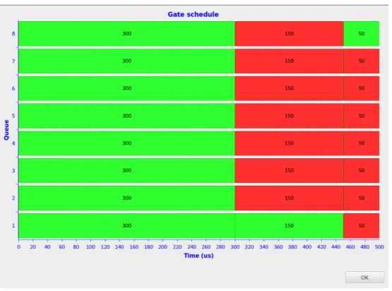
Along with scheduling the flows, TSN also requires gate scheduling of the traffic shaper to ensure deterministic behaviour. As such, the Gate state GUI is responsible for displaying the current gate schedule for switch ports as well as allowing the user to modify the schedule. The gate schedule is defined as a list of entries. Each entry contains an eighth-bit long bit vector representing the eight queues state as either open or close, along with the amount of time before switching to the next entry. The Gate state GUI employs two different views of the gate schedule. The first
Figure 6: Window used to configure gate schedule
view allows the user to added, edit and remove entries in a concise window, shown in Figure 6. The second view displays the states proportionally to their duration using a diagram, shown in Figure 7, and is meant to aid the configuration of TSN schedules by displaying a time period which can be compared to existing designs. Initially, the diagram was meant to also display any flows which passed through the gate, showing when the package would be expected to arrive at the gate and what queue it would be placed in. However, two issues with including the TSN flows in the diagram were identified in the initial design stage. Firstly, adding the flows along with the queue would make the window considerably large and make it difficult to compare gate states with the flow. Secondly, it is difficult to estimate exactly when a package from flows will arrive at a switch, especially if the switch is not directly connected to the source node. If the estimate receiving time is incorrect, the presented diagram would potentially be misleading. As such, it was decided that the diagram would only present the gate schedule for the queues.
5.8
Schedule generation
After the user either creates a new configuration or modifies an existing one in the tool, the tool should either create or update two configuration files which can be used by NeSTiNg. This is the purpose of the schedule generation component, to generate schedule and routing files. This process is similar to how the configuration reader operates but in reveres, converting the TSN flows and gate schedules in the tool into XML readable for NeSTiNg. One difference from the configuration reader is that the schedule generation also generates a flow Identification no, (ID) for each entry. Flow ID is a unique identification number used by NeSTiNg to identify flows during the simulation. While the assignment of flow ID could have been performed manually by the user, it was decided that it would be likely more convenient to automate the assignment.
5.9
TSN flow extraction
Along with simulating many different kinds of networks, OMNeT++ also offers tools for analyzing the results of simulations. However, while it is possible to collect certain useful statistics such as end-to-end delays, the collection process does not differentiate between TSN flows. As a re-sult, OMNeT++ does not offer any built-in functionality for extracting TSN statistics. Currently, obtaining statistics for TSN in OMNeT++ involves either tracing event logs by hand (a chal-lenging and time-consuming process) or exporting the statistics to an external application such as SQLite13 were evaluation is easier. To facilitate TSN statistics collection with a built-in option for OMNeT++, the TSN flow extraction component was also added to the tool. The TSN flow extraction takes a vector (VEC) file as input, which is a file generated after a simulation run. This file records data values as a function of time and stores the results in vector form. The
compo-Figure 8: CSV file generated by TSN flow extraction 13https://www.sqlite.org/index.html
nent searches the VEC file for two specific statistic collections when TSN packets are received, the flow ID and end-to-end delay, and collects the data separate for each flow. After that, a comma-separated values (CSV) file is created with the end-to-end delays comma-separated by TSN flows. An example of this file can be seen in Figure 8.
However, while this is the approach used by the TSN flow extraction component, it has some considerable disadvantages. Firstly, this method requires that the two statistic collections men-tioned are present for each receiving node by adding it to the NED file. This means that it will not work on any result file generated together with NeSTiNg and the user must manually add the statistic collection. Secondly, the current method is not very efficient when processing the data. While this is less noticeable when working with smaller networks and shorter simulation time, this could be a potential issue if the tool is employed on a larger scale. One example of an alternative approach to extracting TSN flow would be to modify the NeSTiNg models to generate a unique vector for each flow, making the statistic data directly available in the VEC file. However, by modifying the model itself, the option to not record statistics would also be removed. If the data is not needed for every receiving node, the modification would lead to an unnecessary increase in computation time and file size of results.
6.
Network configuration use case
In this section, the usability of the proposed network configuration approach is validated by mod-elling an industrial use case with the prototype TSN-configuration tool. The use case was selected as an example of the application of the tool inspired by a real industrial use case. Moreover, this section also presents an end-to-end timing analysis of the modelled system using the TSN analytic extraction of the TSN-configuration tool.
6.1
Use Case Description
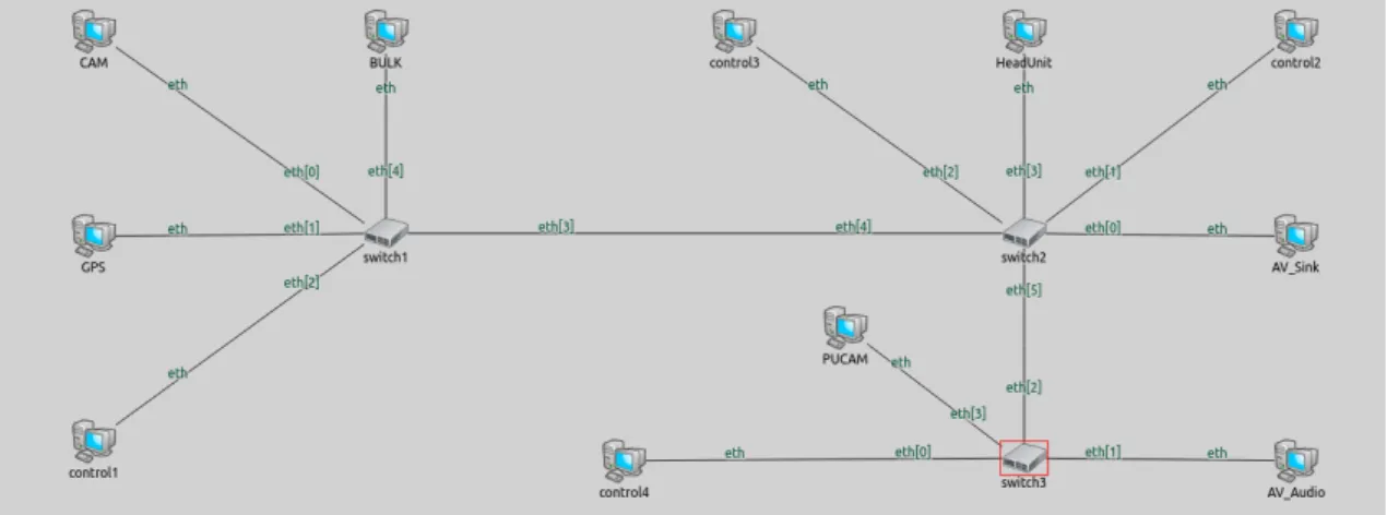
The use case considered in this thesis is inspired by the in-car network system presented by BMW Group Research and Technology [32]. This use case has been used in many existing works for the purpose of validation [33, 34,35]. The use case models several different types of traffic including control messages, camera streaming, video streaming, audio streaming, CAN messages and bulk traffic. The topology of the use case can be seen in Figure 9. The traffic in the network is limited to two classes, TT with a PCP of 7 and BE with a PCP of 0. The test case was also planned to include AVB class A and B traffic which would utilize credit-based shaper together to model multimedia streaming in a fully-loaded network. However, at this time of writing, the current re-lease of NeSTiNg does not support the credit-based shaper together with the ST as the mechanism has been temporally removed from the framework. As such, multimedia streaming in the network either uses the TT or BE class, depending on how critical the media stream is to the system. The topology models an in-car network system with three TSN switches, one near the front of the vehicle (front switch) and two near the rear (left and right switch). In a typical geometrical arrangement in a vehicle, most of Electronic Control Units (ECUs) in a vehicle are located either at the front or the rear, since the space under the passenger cabin is limited and leaves little space for ECUs. This motivates the placement of ECUs to congregate around the front and rear section of the vehicle.
In the use case network, there is a head unit which represents the main processing unit. The head unit is connected to the right switch and functions as a data sink for all the control messages in the network, as well as some video and bulk data. There are four control nodes (control 1-4) in the network which periodically send control messages to the head unit. While the data payload of control messages are most commonly very small, the size has been increased in this use case to further highlight the effect of frame preemption. The control nodes are spread out over the network, with control node 1 connected to the front switch, 2 and 3 connected to the right switch and control node 4 connected to the left switch. As these control signals are critical for the system, they are given the priority of TT.
A camera (CAM) is also placed in the front of the vehicle, connected to the front switch and sends video frames at a regular interval. The CAM generates two streams of data, one transmit-ting driver assistance related video data to the head unit and another transmittransmit-ting to a dedicated processing unit (PUCAM) connected to the right switch which supplies a front view system with video data. While the front view system is not time-critical and given the priority of BE, the driver assistance stream could be considered time-critical as delays would affect drivers safety and are thus assigned priority TT.
The GPS node, connected to the front switch, periodically fetches position date and transmit it to the head processing unit for navigation assist. The audio receiver (AV Audio) node, con-nected to the left switch, generates a stream of high-quality media and transmits to the media sink (AV Sink) used by an entertainment system. As neither the GPS or AV Audio node fulfil any time-critical function, the priority class of these traffic flows are set to BE.
Lastly, the bulk traffic (BULK) node represents an open connection to the internet that con-tinuously transmits bulk data to the head processing unit. The purpose of the bulk traffic in this use case is to populate the link between switches, demonstrating the ability of TSN to provide deterministic behaviour over Ethernet despite traffic load as well as the effect of frame preemption.
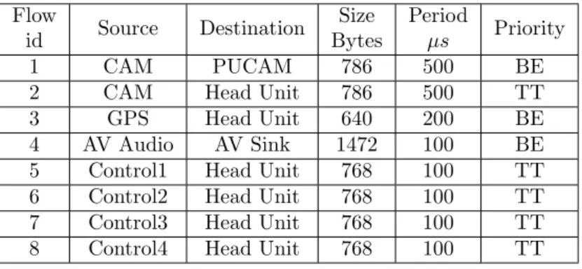
As the bulk traffic represents a data stream generated outside the scheduled traffic, meaning the exact period and size of packages is unknown at it the time of scheduling, is not assigned a dedi-cated flow within the use case and is sending BE traffic to the head unit independently of the rest of the nodes. The network uses gigabit Ethernet connections between every node which transfers at a data-rate of 1 Gbit/s with a transfer delay of 0.1µs. The processing delay is set to 5µs for each switch. Table 1 presents the traffic characteristics in the use case.
TSN Network CAM GPS Control 1 AV Sink Control 2 Control 3 Control 4 AV Audio BULK Switch 3 Switch 2 Switch 1 PUCAM Head unit
Figure 9: Use case - network topology
Flow id Source Destination Size Bytes Period µs Priority 1 CAM PUCAM 786 500 BE
2 CAM Head Unit 786 500 TT
3 GPS Head Unit 640 200 BE
4 AV Audio AV Sink 1472 100 BE
5 Control1 Head Unit 768 100 TT
6 Control2 Head Unit 768 100 TT
7 Control3 Head Unit 768 100 TT
8 Control4 Head Unit 768 100 TT
Table 1: Traffic characteristics in the use case
The use case contains four different configurations on the same network topology. These four configurations are:
1. All gates open with no frame preemption 2. All gates open with frame preemption enabled 3. Gate schedule with no frame preemption 4. Gate schedule with frame preemption enabled
The purpose of these four configurations is to demonstrate the application of the tool under various situations and to establish how the configuration affects end-to-end delays for different TSN flows.
6.2
Modeling of the Use Case with the TSN-configuration tool
The system-level software architecture of the use case is modelled with three different models of nodes, provided by NeSTiNg: VlanEtherHostSched, VlanEtherHostQ and VlanEtherSwitchPre-emptable. VlanEtherSwitchPreemptable acts as TSN switches which can be configured to use gate schedules and frame preemption and are used to model all the switches in the network. VlanEther-HostQ is a simple node which generates traffic continuously thought settings in the INI file and is used to model the BULK node. VlanEtherHostSched generates traffic based on the configuration of the TSN-configuration tool and records TSN-specific statistics when receiving packages from TSN flows. VlanEtherHostSched is used to model every other node in the network besides BULK. The properties of the links are specified according to the information presented in Section 6.1 In addition to these proprieties, the BULK traffic is manually configured to send 1250 bytes packets every 10µs to the head unit using the lowest priority of BE. With this extra traffic, the queue for the connection between switch 1 and 2 is intentionally receiving more traffic than it can drain. This is done to show the effect of a fully populated link in TSN and how different configuration affect this. The finished network topology file can be seen in Figure 10. No start offset was used for any
Figure 10: OMNeT++ network description for the use case
of the flows, meaning the four configurations shared the same topology and traffic characteristics, but with different gate schedules and switch settings. The first two configurations operate with all gates open, meaning that at any given time switches will always transmit packages from the highest non-empty queue available. The seconds two configurations use a gate schedule which is open for TT traffic only for a period of 50µs, and switches after that to only allow BE traffic for 50µs. Note that this gate schedule is defined without using any optimization algorithm. This schedule is set for the ports which connections the switches together. Besides this difference, all configurations share the same TSN schedule and routing setup. Additionally, for the two configurations which utilized frame preemption the link from switch 1 to switch 2 as well as from switch 3 to switch 2 is set to enable preempting of frames in the INI file. Configuration of the flow schedule and routing was done through the TSN-configuration tool, depicted in Figure 11.
Figure 11: TSN flows configured in the TSN-configuration tool
Simulation time of the use case was 1 second for each configuration. While this is a low amount of simulation time, as the network model is configured to receive more traffic than it can process, the queue would eventually reach capacity and terminated the simulation prematurely. As such, the simulation time was set so the simulation finished before this occurred. The statistics collected was written into a VEC file at the end of each simulation. Finally, the TSN results were extracted using the TSN-configuration tool and are presented in the next subsection.
6.3
End-to-end Timing Analysis of the Use Case
In addition to the main focus of this thesis, exploring automatic configuration of TSN networks in simulated environments, extraction of TSN-related statistics it also covered as an opportunity to further extend the usability of the tool. In this subsection the results recorded from the use case is presented.
6.3.1 Configuration 1 - All gates open with no frame preemption
Table 2 shows the end-to-end delays results from the first configuration. As the first configuration uses an open gate policy without any frame preemption, these results works well as a baseline to compare with the other results. We can note that the control signals have a small variation of
Flow ID Source Destination Minimum
µs Maximum µs Average µs 1 CAM PUCAM 58.904 450.904 436.947
2 CAM Head Unit 44.032 56.156 48.918
3 GPS Head Unit 49.488 956.924 925.873
4 AV Audio AV Sink 47.196 47.196 47.196
5 Control1 Head Unit 31.324 49.932 42.159
6 Control2 Head Unit 17.968 28.268 22.525
7 Control3 Head Unit 24.448 34.748 29.005
8 Control4 Head Unit 30.928 46.348 35.495
Table 2: End-to-end timing analysis results of the use case with configuration 1
about 15µs, but never exceeds an end-to-end delay of 50µs. The audio stream, represented in flow 4, has a consistent delay of 47.196µs. Audio stream (flow 4) and Control 4 stream (flow 8) have been set to be transmitted with the same period and they are also sent with the same path links.
![Figure 1: The process of System Development Research [31]](https://thumb-eu.123doks.com/thumbv2/5dokorg/4559744.116347/15.892.295.610.343.856/figure-process-development-research.webp)