Postadress: Besöksadress: Telefon:
Box 1026 Gjuterigatan 5 036-10 10 00 (vx) 551 11 Jönköping
Product development and design of
industrial sensors
Moa Andersson
MASTERTHESIS 2017
Master in Product Development with a specialization
INDUSTRIAL DESIGN
Postadress: Besöksadress: Telefon:
Box 1026 Gjuterigatan 5 036-10 10 00 (vx) 551 11 Jönköping
Produktutveckling och design av
industrisensorer
Moa Andersson
This degree project is performed at the School of Engineering in Jönköping in the subject field Industrial Design. The project is a result of the master program Industrial Design. The writers are responsible of the result, conclusions and reflections.
Tutor:Lars Eriksson Extent: 30 points Date: 14/06/2017 Filing number:
ii
Abstract
IoT- technology, Internet of Things, is a fast-growing business, it means that more and more products, clothes, even people are provided with sensors that can communicate and perceive the surroundings to create a smarter community. For companies to keep up to date, it is essential to continuously provide products with better components and reduced size. To stand out further, companies should provide revolutionary products, with totally new feature. One of these ideas, of a new kind of product with special features, have been investigated and developed in this thesis.
The thesis has been conducted with the company CombiQ, located in Jönköping, Sweden. The product that was going to be developed was an industrial sensor, that uses the technology of IIoT, Industrial Internet of Things, that the company develops. At the time when this project took place, CombiQ did not sell any own product, only the technology that was placed inside the products.
To develop the industrial sensor for CombiQ, not only the functions of the product had to be investigated, further the brand had to be analyzed to create a design expression reflecting the company.
Through implement several tools and methods, from among other things the product development process and design thinking, a concept of an industrial sensor is presented that fulfill the specific requirements and functions. Where the main-feature is that the sensor should be a modular solution to be adjusted for the specific need of the clients. Furthermore, during the project a visual brand language with design guidelines have been developed to reflect the design aspects of the company CombiQ. Design guidelines can be used for further product for the company in the same manners, which also has been displayed by developing design concept of the rest of the industrial sensor that counts to the same product family as the modular sensor.
Due to confidential agreements with the cooperating company, the design of the final concept and some functions cannot be shown in the report and are then covered.
iii
Sammanfattning
IoT-teknologi, Internet of Things, är en snabbt växande marknad, det innebär att mer och mer produkter, kläder, även människor förses med sensorer som i sin tur kan förstå omgivningen och kommunicera, detta för att skapa ett smartare samhälle. För att företag ska kunna vidhålla positionen på marknaden är det viktigt att hela tiden erbjuda produkter med bättre komponenter och mindre till storleken. För skapa en starkare position, företaget borde erbjuda revolutionerande produkter med unika egenskaper. Det är en av de här idéerna som har undersökts i det här examensarbetet.
Arbetet har skett under ett samarbete med företaget CombiQ, belägen i Jönköping. Produkten som skulle tas fram var en industriell sensor, som skulle använda sig av IIoT-teknologin, Industrial Internet of Things, som företaget utvecklar. Tidpunkten när det här arbete utfördes, CombiQ hade inga egna produkter men all teknologi som sitter i sensorerna.
För att ta fram en industriell sensor för CombiQ behövde inte bara möjligheterna att tillverka en produkt utefter funktionerna undersökas. Varumärket behövde även analyseras för att utveckla en produkt som uttrycker företaget och dess varumärke på rätt sätt. Genom att tillämpa metoder och verktyg från både produktutvecklingsprocesser och designprocesser, kunde ett koncept tas fram som uppfyllde de uppställda kraven och funktionerna. Den huvudsakliga funktionen i sensorn var att produkten skulle bestå av moduler och på det viset kunna justeras utefter vad kunden behöver. Vidare, under projektet har även CombiQ som varumärke undersökts och riktlinjer för designen har tagits fram som reflekterar företaget och dess varumärke. Design riktlinjerna kan användas för att ta fram ytterligare produkter med samma maner, vilket har visats i detta arbete genom att ta fram designkoncept på ytterligare produkter som räknas till samma produktfamilj som sensorn med moduler.
På grund av sekretessavtal med företaget, som ingått i samarbetet, kan inte designen och vissa funktioner som ingår i det slutliga konceptet och resultatet inte visas i denna rapport och är därmed övertäckta.
iv
Table of Contents
Abstract ... ii Sammanfattning ... iii Table of Contents ... iv 1 Introduction ... 7 1.1 Background ... 7 1.2 Objectives ... 9 1.3 Delimitations ... 10 1.4 Disposition ... 10 2 Theoretical Background ... 11 2.1 Design thinking ... 11 2.2 IP-class demands ... 14 2.3 Circular connectors ... 14 2.4 Materials ... 15 2.5 DFMA ... 162.6 Process methods, molding ... 17
2.7 Design guidelines for molding ... 18
3 Method ... 20 3.1 Project planning ... 20 3.2 Functional Analysis ... 20 3.3 Morphological chart ... 22 3.4 Requirements ... 23 3.5 Waterproofing ... 23 3.6 Anthropometry ... 24 3.7 Kansei Engineering ... 24 3.8 Design equalizer ... 25
3.9 Visual brand language ... 25
3.10 Moodboard ... 26
3.11 Sketching techniques ... 26
3.12 CAD modelling techniques ... 27
3.13 3D rendering ... 28
3.14 3D printing ... 28
v
4 Approach and Implementation ... 29
4.1 The process ... 29
4.2 Project planning ... 30
4.3 Given idea of modular sensor ... 30
4.4 Emphasize ... 31
4.5 Define requirements ... 31
4.6 Circular connectors ... 33
4.7 Ideate functional concepts ... 34
4.8 Visual brand language ... 36
4.9 Ideate design concepts ... 39
4.10 Deciding the final general shape ... 41
4.11 Final refine process ... 47
4.12 Visual Brand Language ... 53
4.13 Product family ... 55
4.14 Visual prototype (model) ... 57
5 Result ... 59
5.1 Is it possible to do a modular solution that fulfill or exceed the specific requirements? ... 59
5.2 Which design values express and define CombiQ as a brand? ... 62
5.3 How can a product-family be conducted for the brand CombiQ? ... 63
6 Conclusion and discussion ... 65
6.1 Achieved result... 65
6.2 How to be continued ... 67
7 References ... 70
8 Attachments ... 76
8.1 Attachment 1: Table on IP-classification ... 77
8.2 Attachment 2: Design guidelines for assembly ... 78
8.3 Attachment 3: Anthropometric for hands ... 79
8.4 Attachment 4: Process tree... 80
8.5 Attachment 5: Functional Analysis ... 82
8.6 Attachment 6: Technical specifications ... 83
8.7 Attachment 7: Morphological chart ... 84
8.8 Attachment 7: Technical concepts ... 85
vi
8.10 Attachment 9: Design values ... 89
8.11 Attachment 10: Evaluation of logos ... 90
8.12 Attachment 11: Presentation of the modular sensor ... 91
8.13 Attachment 12: Presentation of the bracket & holder sensor ... 93
8.14 Attachment 13: Presentation of the personal tag, card version ... 94
7
1 Introduction
This report is carried out as an exam work of a 2-year education on advance level, within the field of product development specialized in industrial design.
It describes the project, from research phase to final prototype, for an industrial sensor including all the problems that had to be solved and how to construct the product. Meanwhile a new design language had to be developed for the cooperating company since no existing products were developed.
1.1 Background
This chapter will give an introduction of the company as well as the problem to be solved in this thesis.
1.1.1 The company, CombiQ AB
The company CombiQ operates in the IT-field, they are developing solutions within IoT, mostly IIoT. [1]
IoT, Internet of Things, is a collective term for the development to put sensors and computers on machines, vehicles, clothes, etc. [2]
IIoT, Industrial Internet of Things, is the term used when the IoT-technology are used in the industry. It can be used to monitor the machines by collecting data and by analyzing it the companies can detect inefficiency in the production or to schedule maintenance to prevent machine failures. [3]
By using these technologies CombiQ creates the internal components for wireless sensors that can be used in a wide range of fields and can be constructed to collect different data, which can be customized depending on the need. CombiLog system, is one of the services that CombiQ offer their customers, it is fully adaptable sensor platform that can be customized for the specific need. The sensor will be adapted depending on the need for example; which data that has to be measured, sampling frequency, battery capacity. The data to be collected can be; number of revolutions, vibrations, temperatures, etc. This data is then transformed wirelessly to a cloud-based service and CombiQ offer a customized solution for how the data should be presented. [4] In other words, CombiQ is offers a complete IIoT-solution that can be used in sensors by clients, yet not the complete developed sensor as a product.
The company are during a growing state and count on growing fast during the next upcoming years. They offer a service from development to production; from listing the specification for the need, to production of the product. With a knowledge to work with series production and to fulfill certifications.
One of the names that CombiQ has worked with is Husqvarna, where they have been the lead developer behind their new wireless system. [5] CombiQ has also cooperation with Phoniro, that is one of the leading companies in Sweden when it comes to tools and aid for the elderly care sector, unlocking doors for staff members, personal alarms, etc. [6]
8
1.1.2 Assigned task
CombiQ is in the front edge at the development of the IIoT-technology and is starting up a new project to develop a whole complete IIoT-solution, from the technique to the design of the sensor. At the time when this thesis start, CombiQ does not have their own design and product for sensors, that goes under their own brand. Mainly every client has their own design of the sensor with their own logo and CombiQ stands for the technology behind it. By developing a new solution with the CombiQ-logo and own designs on sensor will give the opportunity to be more visible on the market. Besides, the company also can offer a whole solution for companies that does not have their own designs on sensors.
To offer the whole product package in the IIoT-solution there must exist different variants of the sensors for different applications. There are sensors that will be installed on hand-held machines, industrial machines and motors, there is also personal tags, in two variations. These products will have to be designed to express the company CombiQ-logo and design language.
One of the industrial sensors that are going to be developed, for application on the bigger industrial machines, are going to be based on an idea from CombiQ. It involves a possibility of a modular solution, which amplifies the customization for the product and let the client put together what they need and the possibility to do it when the demand appears.
The main question in this project is to investigate the possibility to solve the modular concept and to fulfill the strict demands there is on a sensor, that will be placed in an industry. By constructing the product with several modules, it can be built together with the modules that is needed and be changed if the needs changes. The sensor is supposed to withstand a IP-class 67 and it puts requirements on the construction and components of the product. To be able to investigate if the product is possible to produce, all the technical requirements must be considered and to find components that will ensure that the product will fulfill the IP-class.
Since there is no existing product or design language for CombiQ during this thesis, one of the questions will concern this. The brand should be analyzed to find the design values that rightly will express and reflect the brand name. In the new project and future-plans at the company CombiQ, is to develop and offer the whole IIoT-solution with all the products that will be needed. This means that the design that will be put on the sensor in this project will have to be able to be copied and applied to the rest of the products. To make that possible design guidelines should be defined to facilitate the further design processes. The foundation for the design guidelines will be to analyze and list design values that express CombiQ as a brand.
9
1.2 Objectives
In the previous chapter, assigned task, it clearly states that the main point in the thesis work will be in a modular solution of an industrial sensors. Furthermore, to provide the company with a design on the sensor that will express the brand, it must be an analyzing and definition of their design values. By facilitate CombiQ’s further design development, design guidelines will be listed and applied as an example how their product family can look like. The purpose is to investigate and report to the company whether the modular solution of the industrial sensor is possible to manufacture or not. If this is possibly it will give a great purpose for the company since they are launching their new complete IIoT-solution. To be able to fulfill the purpose of this thesis work, the problem has been divided into three research questions that are going to be investigated during the project. The first research question that are going to be conducted is;
[1]IS IT POSSIBLE TO DO A MODULAR SOLUTION THAT FULFILL OR EXCEED THE SPECIFIC REQUIREMENTS?
The requirements will be stated by the company and the inner components will be decided through cooperation. When the possibility can be stated, whether the modular solution is possible or not, the next matter is to investigate how the CombiQ should be reflected. How the brand should be expressed in the design by defining the design values and guidelines that reflects CombiQ, therefore the second research question is;
[2]WHICH DESIGN VALUES EXPRESS AND DEFINE COMBIQ AS A BRAND?
First, CombiQ must be analyzed as a brand and design values listed, which reflects the brand. The next step will be to use the design values to create a design on the modular sensor. By letting the company interact through this process the design in the end will contain what the company are looking for. Left on in this second research question is to make sure that the design from the modular sensor can be applied for future products. Which allows the design values and design of the modular sensor to be a foundation for further designs. To investigate how it is possible to work with design guidelines and to apply it on new products, the third, and last, research question is;
[3]HOW CAN A PRODUCT-FAMILY WITH SAME DESIGN LANGUAGE BE CONDUCTED FOR THE BRAND COMBIQ?
The output of the third research question should be a suggestion how the product family for CombiQ can look like based on the brand values and the design of the modular sensor. To be able to answer all the research question and then meet the purpose of the thesis, there will be implementations of methods and tools from both product development processes and design processes. Along with research, manufacturing processes and material selections. With these methods and research, the result of the modular sensor is expected to be presented as digital rendering and a visual prototype. Meanwhile, the suggestion of the product family is intended to only be visualized digitally.
10
1.3 Delimitations
This thesis is conducted during a period of 21 weeks and are not possible to deliver a complete and flawless blue-print ready for manufacturing. Since the thesis also includes the analyzing and development of design guidelines for the company. Although the goal of the thesis is to get as far as possible to a get the sensor ready for manufacturing.
The prototype of the sensor in the end will be a visual prototype, which means that it will not be manufactured in the intended way or material. The design of the prototype will be as the intended modular sensor, in a scale 1:1, and will have the right colors with textures. Which functions that can be included depends on the access of materials and tools. The components inside the product with placements and connections, will not be covered in this thesis, since it outside the framework of the educational program. The internal components will be decided of the collaborating company in this thesis work, since it is their specialization and knowledge.
The product is planned to be produced by injection molding, which includes that a tool will have to be made for the production for the product. In this thesis, the tool will not be constructed, even though the manufacturing process with its specific constraints are considered when developing the product,
When it comes to the product-family, the concepts will not be as refined as the modular sensor. The product-family will not be presented as visual prototypes, the intention is to give a suggestion for the company. Therefore, they will not be developed in the same extension with manufacturing processes, material selection nor functions.
Due the time-limit the visual brand language and the design guidelines cannot be fully defined. It will be analyzed and defined to a limit where it can be used and applied in this project.
1.4 Disposition
The report is further constructed in a way where first the theoretical background is stated. Further the methods that is applied in the thesis will be defined, followed by the implementation of these methods, to finally lead up in the result and discussion. At the end of the report all the references and attachments can be found, that is referenced along the report.
11
2 Theoretical Background
To create the framework for this thesis, several theories have been implemented to create a structured workflow through the project. In this chapter, all the theories are stated, from the design theories to the manufacturing processes.
2.1 Design thinking
The definition of what designing thinking really implies, are scattered. [7] The Nielsen Norman Group states that the design thinking is an ideology that is supported by an accompanying process. [8] To mention design as a way of thinking can be traced back to 1969 and Herbert. A. Simon’s book ‘The Sciences of the Artificial’. [7] [9]
The first one to adapt the design thinking for business purpose, was the founders of IDEO, a global design and innovation firm stated in 1991. [10]
IDEO have defined the design thinking as a process with three major stages;
1. Invent: Form some theories of what the costumers want and try to see into their life’s, to see what their wants and needs could be.
2. Test: By testing your ideas for the costumers with quick prototypes. See how the costumer respond and adjust the product out of that information to become better. 3. Life: bring the product or service to life by analyzing the winning concept to collect information what kind of capability, resources and activities that the company needs to have to produce, display and sell their product. [11]
By using design thinking, the development process can take a human-centered approach, which lead to a result that fulfill and respect the need of the user. [11]
2.1.1 Bootcamp bootleg
Originally Bootcamp Bootleg was a guide for the graduated students at d.school at Standford University for their class Bootcamp: Adventure in Design Thinking. The Bootcamp Bootleg can be seen as a toolkit for supporting a design thinking process. The guide goes through all the steps of the process and with examples of methods to apply to perceive a human-centered design process. [12]
The Bootcamp Bootleg is divided into a process of 5 steps; 1. Empathize
In human-centered design it is vital to understand the user you are designing for and what they go through. In order to build a empathy for the user it is important to observe, engage and immerse. Which means that you should watch people interact in the intended environment, engage people to reveal what they think and what values they have. You should also put yourself in the position of the user to get the same experience. All of this will give an understanding who you are designing for and get perception of the experiences that the users will go through. [12]
12
2. Define
The next step is to translate all the information from the empathy phase to the users’ needs. The goal is to have a definition of an actionable problem, based on the uncovered problems that was presented in the empathize stage. The statement should focus on specific users and their needs.
This step is important since it will be the foundation for the design process, this will give crucial information for further work and define the problem that must be solved throughout the project. [12]
3. Ideate
When the problem is stated, the ideate-phase can start. This involves producing as many concepts and ideas as possible that solves the problem. In this phase, it should be a wide range of ideas and solutions that later can be explored further. [12]
4. Prototype
Prototyping let the ideas become real and be evaluated in a physical way. In the early states the prototypes should be rough and rapid, to allow quick investigation of a wide range of ideas and solutions. The prototype can be made out of anything available, it could be paper and tape, roleplaying activity, an object, etc. As long as the prototype will test the ideas in a way that they can be investigated and evaluated.
The ability of the prototype does not have to be functional, it could also be used as a test for exploring shapes, give inspiration or gain more empathy of the design and the user. [12]
5. Test
The testing phase is about getting feedback from the solutions that has been refined. This is an interactive phase with placing the solutions in appropriate context of the users’ life. This step reveals the faults and can lead to a step-back to the drawing board or redefining the problem statement. On other hand, this step also gives the opportunity to build stronger empathy and new insights. [12]
2.1.2 Design thinking 101 by Nilsen Norman Group
The Nielson Norman Group, NN/g, was established in 1998 of Jacob Nielsen and Don Norman. The purpose was to conduct high-quality user experience research and based on that provide recommendations for interface design. In 2000, Bruce Tognazzini joined the group, he was one of the first human-interface designers at Apple. [13]
The definition of design thinking according to NN/g is that the design-thinking ideology states that the user-centric and hands-on way of working can lead to innovation, differentiation and competitive advantages. The ideology in it selves is defined by the design-thinking process with 6 distinct phases. [8] See figure 1.
13
Figure 1. Design thinking process of NN/g. [8]
The NN/g’s framework of the design thinking consists of 3 overall flows; understanding, explore and materialize. In these 3 flows it is 6 phases;
1. Empathize: through research get an understanding of what the users do, say, think and feel.
2. Define: Investigate where the users’ problems exist and define their needs. 3. Ideate: Creative a wide range of ideas that fulfill the users’ needs.
4. Prototype: Build physical models of some of the ideas. To allow an understanding of what must be define, changed or if they even work. The evaluation of feasibility starts to have a greater impact during this stage.
5. Test: Gain feedback from users, investigate if the ideas achieves the goals. Continue to test along the refinements of the ideas.
6. Implement: Ensure that the solution is materialized and that it the vision will be put into effect. [8]
Further NN/g mention that the design process is not linear, all the phases do not have to be followed to the letter. The process will have to look different depending on the project with its including parts. The different steps may need to be repeated to process the problem.
14
2.2 IP-class demands
An IP-class are defined by the two numbers, see Attachment 1 for a table on definition of the different levels on IP-classification. The first number in the classification describes the level on mechanical intrusion of dust and water. The second number states the resistance when exposed to pressure. And IP-class 67 defines a product that have the highest level for mechanical intrusion of dust and water, since it has an IP-class 6X. when it comes to resist against water an IP-class X7 must withstand the pressure to be under 1 m water, for 30min. [14]
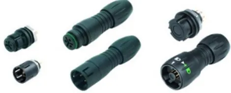
2.3 Circular connectors
A circular connector is an electrical connector consisting of a cylindrical housing possessing multipin interconnects. The advantages of circular connectors are the ability to house different contacts and they also come in a wide range of allowable contact voltages and currents. The disadvantages are the loss of space when placing circular connectors in arrays. [15]
The connectors come in two variations; one female and one male. The female is the one to the right in figure 3 with holes for the pins that are one the male connector to the right in the picture.
There are different types of circular connectors that differs with number of pins inside the connector and the arrangement of them. There are also several ways that the connectors can be constructed depending how it will be installed and also different ways to connect two connectors together. [16]
In the figure 4 below, two different circular connectors are displayed. They are with different types of connection between the male and female, from right; push- and pull connection, bayonet connection.
Figure 4. Circular connectors [17] Figure 3. Female and male connectors
15
2.4 Materials
To be able to manufacture a product, the possession of a material is essential. It exists a wide spectrum of materials on the market, each have their own features.
There are two main groups of materials; the industrial produced material, for example; steel and then it is the materials that is naturally occurring, such as wood and stones. [18] 2.4.1 Plastic
Plastic is a synthetic material that is built up by one or several polymers and by additives it can achieve improved characteristics and properties. Plastic materials can be divided into two groups, thermoplastics and thermosets. Thermoplastics have a molecule-structure that allows it to be melted, formed and with the ability to be melted again and in that we be recycled. The thermosets on the other hand, cannot be recycled by being melted again and reshaped. [19]
The most common manufacturing method for thermoplastics is injection molding, extrusion and thermoforming. Where the injection molding is the most used method, which can be used to produce products, from small details to big containers. The plastic is melted and further injected into the mold cavity where it is cooled down. Injection molding is a method that allows the molded product to have a high accuracy on dimensions and tolerances. [20]
The thermosets commonly produced by compression molding, where the plastic is melted and poured into a warm mold where it will be hardened under pressure. [19]
2.4.2 Gore-tex®
Gore-tex®, is the trade name for a material that “breaths”, basically it lets air and
water-vapor pass through but not water drops. The structure consists out of a microporous membrane of expanded polytetrafluorethylene plastic which is usually either laminated or sewn between two layers of fabric to create waterproofed clothing. [21]
Gore®, that is the concern behind all the branches of Gore-tex® application, also have a
branch with Gore® Vents. Where their technology is applied into vents to be used for
industrial applications. The vents are constructed with ePTFE structure, consisting out of odes, fibrils and pores. It allows air and sound to come through and protects against water and particles. The vents are developed to give a high transmission of sound. [22]
16
2.5 DFMA
Design for Manufacturing and Assembly, DFMA, is consist of the combination of two methodologies; Design for Manufacturing (DFM) and Design for Assembly (DFA). The focus is to decrease the production cost and by looking at both DFM and DFA the cost can be reduced within all the steps in the process, from the design to the production and assembly. [24]
DFM is focusing on the manufacturing of all the components that a product consists of. Meanwhile the DFA concerns to facilitate the assembly of the manufactured parts for the product. [24]
The goal of the DFMA is to evaluate the product and simplify the product structure as far as possible, to eliminate costs in manufacturing and assembly. DFMA can also be used as a tool for benchmarking, for study the competitors’ products, and it could also be used as a ‘should’-cost tool for supplier negotiations. [24]
The workflow for a DFMA;
1. Start with a proposed design 2. Estimate the manufacturing costs 3. Reduce the cost, concerning;
- Components - Assembly
- Supporting production
4. Understand the impact of other factors 5. Re-compute the manufacturing costs 6. Evaluate proposed design. [24]
The choice of process and material are determined based one production volume, tools, tolerances and product geometry. The process will have to consider the functions in the product, such as; strength, structure and geometry. The most cost-efficient process should be chosen that still ensure that the product fulfill the constraints and tolerances. The material will be determined based on the constraints and the geometry of the product such as; thickness, cavities, etc. [24]
When designing the details for a component or product, there is guides that can help to avoid mistakes in manufacturing. Components should be reduced, meanwhile the design of the details should make it easy to assemble. [24]
By going through the parts that constitutes costs for the manufacturing, problem can be found and erased to reduce the costs. Following, some steps are presented where the costs can be reduced in the production;
Reduce number of components
By reducing the number of components or parts of a product, the costs for the manufacturing and assembly can be minimized. [24]
17
To analyze and get to the theoretically lowest number of components, each of them can be evaluated by some questions;
- Must the component be movable compared to the parts around it?
- Can the component be eliminated or combined with another component?
- Must the component be separate because it should be serviced, or because of the material choice, is it possibility to replace it or is it a theoretical necessary part? [24]
By reducing the number of parts in the product it will lead to easier assembly and reduction of the assembly time and complicated tolerances. By minimizing the assembly time, it will also reduce the cost for the assembly and the final production cost. [24]
2.5.1 Reduction in assembly line
To minimize the assembly time, following points can be evaluated and improved in the design;
- Easy to grip the parts without tools and without parts getting stuck together. - Easy to orient the part; symmetric or clearly asymmetric.
- Ease the assembly; self-adjusted parts, chamfers as guides, one base part, mounting directions.
- The parts should be able to be handled with hands, therefore the parts should not be; sticky, slippery, fragile, sharp or flexible. [24]
See Attachment 2, for example on guidelines for designing details that facilitate assembly. 2.5.2 Other factors
To understand the impact on other factors, such as parts that could be used in other products in a company’s assortment, which in this case can be cost efficient based on tools and machines for the company.
Another factor that can be examined is the whole life cycle of the product, with the maintenance, upgrading and the rest material in the production, that must be taken care of. Which can also arise extra costs for the production. [24]
2.6 Process methods, molding
Molding is a method that is used to shape material, it can be metal, plastic, glass, etc. Molding includes a liquidized material that is put in a mold, with a negative cavity of the wanted product, to solidify. [25]
2.6.1 Insert molding
Insert molding, or two-shot molding, uses the injection molding method as a base for this process. The insert molding allows parts or products to be made from a variety of materials. Inserts are put in the mold to give higher strength and the plastic is injected into the mold, creating a solid body around the inserts. One method of insert molding with multicomponent as inserts, is that the part will in steps put in different molds, as many steps
18
that it is variation of material or color. [26] The figure 6, shows how the process can look like when using an insert molding with two steps. First the pre-formed components are molded in with plastic to in the next step get another type of plastic to create the finished product.
Figure 6. Robot transfer method of insert molding [26]
2.6.2 Low-pressure molding (LPM)
The process of low pressure molding starts with melting the plastic pellets to a temperature of 180C - 210C. When the pellets are melted, the plastic are injected into a two-part mold. The electronics are placed in the mold before the plastic are injected with low pressure and heat, and will therefore be covered during the process. In this method, the parts are usually done within a cycle of 30 second and are immediately ready to be tested. Low pressure molding allows a complete concealing of fragile components and sensitive electronics due the low-pressure injection and temperature. [27]
Technomelt, which is a company providing machines and materials for low-pressure molding are using naturally occurring raw materials. The material can be chosen with a customized color option and Technomelt provide a range of materials for operating temperatures between -40 to 170ºC. [28]
2.7 Design guidelines for molding
To let a component be produced repeatedly times, a tool can be created with a negative space of the component and be used for example injection molding.
The tool is generally made of pre-hardened steel, hardened steel or aluminum, and it can have details out of beryllium-copper alloy in areas where it requires fast heat reduction during the molding. The most economical choice of molds is the one made of aluminum, by using a CNC-machine the mold can be constructing with the right geometry of the components that will be molded. [29]
To prevent many mistakes and faults in the component after the molding, it is important to consider factors such as tolerances, shrinkage, thickness on geometry dimension on radiuses, etc. [30]
To prevent faults in the components after the molding, there is guidelines that can help to do a well-fitted design from the beginning;
19
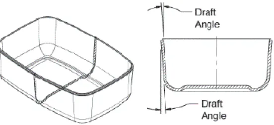
Draft angles
Draft angles are essential to be able to release the component from the mold without damaging neither the mold or component.
How large the draft angle should be, depends on the structure of the surface, the deeper structure the larger draft angle is required. [29] Common for a molded plastic piece is a draft angle between 1° to 3°. [31] [32]
The draft angles should also be applied to texturing
and lettering. A general guideline can then be min. 1.5° per 0.025 mm depth of texture. [29]
Parting line
To be able to get the component out of the mold, the mold itself must consist out of two parts. Where the two parts of the mold meets, a parting line occurs. [33]
Sharp corners
Sharp corners should be avoided in the design, since this leads to increased stress concentration that could lead to part failure. [29]
In figure 8, it shows a general rule how for the radius of the corner based on the wall thickness on the detail.
2.7.1 Inserts
To provide place for fasteners, for example machine screws, an insert can be placed in the plastic part. The insert is generally made of brass and therefore robust, which leads to a better resistance, so that the product can withstand several cycles of assembly and disassembly. [29]
There are several methods to apply the inserts such as ultrasonic- or thermal insert. Then there is the molded-in insert. When using the molded-in process the insert is placed in the mold during the molding cycle. This gives a complete enclosure with plastic around the insert. [29]
Figure 7. Use draft angles to be able to remove component from mold after the process. [29]
Figure 8. Rule for corner radius. [29]
20
3 Method
Within the theories several methods can be used to provide the expected result. In this chapter, all the methods that is used in this thesis are listed and explained.
3.1 Project planning
To get a strong foundation for a project it is important to have a well-defined project plan. It should contain clearly stated goals and who have the responsibility for what. To keep up the efficiency of the project it is also important to continuously follow-up the project and goals. When it comes to plan all the activities in a time-line, Gantt chart is one of the most common way to organize projects in time-lines. [34]
Gantt chart
The Gantt chart was created by Henry L. Gantt during the World War I, to facilitate the production control. [35] [36] A Gantt chart is a tool to create the most suitable plan for a certain task. [36]
By making a schedule with all the activities that has to be done to fulfill the main task, shown in a time-line by horizontal bar charts. The Gantt chart reveals the whole process from start to end, it can also be preliminary dates that the project aims for. The activities show their relationship to one another, which depends on each other and have to be done first. The resources for each activity can also be displayed. The activities are assigned the specific time to be finished, deadlines can also be put up. [37]
Microsoft project
Microsoft have developed a program for planning and monitoring projects, called Microsoft project. In this program there is templates, for example to do a Gantt-chart. Furthermore, the program allows more tools for project planning and to organize staff member. [38]
3.2 Functional Analysis
Functional analysis is a method used for creating a structure with the functions for a product, that are going to be developed. The output of this method is a function-structure, describing the function or system of the product, without any concerns about material or design of the including components. Which allows to get an overview of what the product should be used for and how it should be used. The components of the product can then be defined from the function structure and developed for the specific need.
This method forces to use highly abstract thinking of the product and it that way help to prevent the designer to jump into conclusions in the development process. [39]
The functional analysis can be executed in different ways, depending on the certain project and wanted output. It can be put up like a process tree, a collection of general functions or a combination of both. [39]
21
3.2.1 Process tree
A product goes through different processes during its lifecycle. A process tree is a schematic diagram that allows the designer to go through all of the processes and analyze how the product are going to be used, by who and where. During the processes that the product goes through there is several requirements, and in a process tree, these are listed. The processes in a lifecycle of product that can be investigated are; manufacturing, assembly, distribution, installation, operation, maintenance, use, reuse and disposal. [40] A process tree should be done in the beginning of a project and the steps could be following;
1. Define the product: what is it?
2. List all the relevant processes that the product is going to go through and that is important for the project.
3. Describe all the steps that the product is going to go through in the respective process in the lifecycle.
4. Summarize all the collected information and visualize the process tree. [40] 3.2.2 General functions
In a functional analysis, all the relevant functions should be listed and be ranked in the level of important for the functions of the product. The functions should be built out of sentences with verb+noun to define the different functions of the product. When the functions are listed, they can be defined with limitations. [41]
Main function
The first function to define is the main function, this should be narrowed done to one function. It is the function that the product is used for and if this is not fulfilled the product is useless. A coffee cup for example, can be seen to have the main function: provide fluid intake. Thus, if the coffee cup cannot provide the user with intake of fluid, the main function is not fulfilled and it cannot be used for its purpose. [41]
Necessary functions
These functions are the ones that support the main function and without them, the main function cannot be fulfilled. The necessary functions are usually few to the amount. To continue the example of the coffee cup, from the previous step, the necessary function can be; hold fluid, offer filling of fluid. Without these functions the main function with ‘provide intake of fluid’ will not be fulfilled and the product is useless. [41]
Desirable functions
The desirable functions are not necessary to fulfill the purpose of the product. Nevertheless, they can be seen as something desirable, that can help the user of the product. [41] In the case of the coffee cup, one desirable function can be: allow lift, which help the user to drink
22
the coffee but the product will still work even if it cannot be lifted, since it can be solved in another way. Even tough, a handle can be desirable for the user to get a good experience of the product.
Unnecessary functions
These functions are, as they sound, unnecessary and will not affect the products main function at all. [41] Nevertheless, these unnecessary functions can be something extra in the product, that makes it more special. For the coffee cup, it could be; contain cookies, it is not a function that will support the main function. It will be a function that can make the product be seen as special and give the user the ‘extra something’.
How to put up a functional analysis
A functional analysis can be compiled together with the output of the process tree, with the “use”-stage as a starting point. A functional analysis only describes the functions that the product should do. The functions that are depending on manual work are called: user tasks. The user tasks can usually be connected to some supporting part in the product, which can be considered when the designer is developing the product. [39]
When the functional analysis and process tree have been considered, all the functions can be compiled in boxes and be put in a tree-diagram with the main function on top and the sub-functions underneath ordered in how they depend on each other. [40]
3.3 Morphological chart
The aim of using a morphological chart is to find all the theoretical possible solution to a problem. The method is conducted by first, define all the parameters that might be the solution to the problems. The parameters must be independent, otherwise the different solutions of the parameters cannot be combined freely. To make sure that the morphological chart does not get too large and unbearable, it should be a small number of parameters. Since, all the parameters are supposed to be combined with each of the other parameters to create concepts. A morphological chart that is 10x10 then gives 1010 solution
which will create unbearable amount of concept to try out. By defining only the essential parameters, it will keep the matrix to a feasible size and still give enough defined concepts. When the parameters are defined with the including variation of solution, a morphological chart is constructed from the parameters and all the variations of the solution of every parameter. This will create a multidimensional matrix.
This can then be used to combine one solution of every parameter to create concepts where all problems are solved. [42]
In figure 10, an example is illustrated on how three concepts can be combined with the different solutions and parameters. All the concepts start with the solution 1 of the first parameter. Then the concepts variates on the second up to the fourth parameter.
Solutions Parameters 1 2 3 1 2 3 4
23
In the end three different concept will be created. Further the process can go on until all the combination have been done.
The concepts in their turn should be evaluated carefully, since the morphological chart are based on theoretical underlay and does not ensure flawless concepts in the end. [42]
3.4 Requirements
Requirements can be used as a contract between the costumer, user and company to make sure that all the parts are specified that the product in the end must fulfill. [41]
Design requirements
The design requirements can be listed based on several users of the product, there is design requirements especially for the end-user as ergonomics, satisfying needs, easy to install, etc. It can also be based on the products life cycle, such as; production, retailer, brand, environmental demands, etc. [41]
Technical requirements
The technical requirements are a list of what the product must meet or exceed, in these requirements specified details about, for example, physical or class demands are listed. [43]
3.5 Waterproofing
With products, that in one or another way, should resist water must be waterproofed. Depending on the constraints and demands of the product this can be done in different ways. For examples cellphones have been waterproofed and still managed to have the same aesthetics on the outside with no signs on the waterproofing. [44]
Based on construction
To achieve a well-sealed product, that reaches high demands. Without having a great knowledge about constructing waterproofed products, the golden rule is to keep the shape simple. [45]
Tips for constructing waterproofed components;
o Keep the opening shape circular, in this way it can be sealed with standard O-rings, which also create an unformed sealing force.
o Avoid sealing between more than two parts, it will become a greater challenge to achieve proper sealing between three or more parts.
o The gaskets should have a proper support on all sides, otherwise it will tend to release and cause failed sealing.
o The stiffer parts, the easier to seal. Tolerances on plastic deflection and load of gaskets must be taken into consideration.
o The goal is to still have air coming in and out of the product but not liquids. Membrane vents can be used to create this. The air has to come in and out of the product otherwise it will risk exploding due to the changes of air pressure. It will also give water, that have gotten in, to vapor and get out instead of being trapped. [45]
24
In some product this cannot be applied, the product may have to be sealed in another way than with a gasket and standard O-ring. Enclosure can be achieved with other options, such as;
- Insert molding with elastomeric over molding - Hot plate welding
- Ultrasonic welding - Liquid adhesive - Tape
- Encapsulation the sensitive components [45]
3.6 Anthropometry
Anthropometry is the study of the measurements of the human body. [46] In ergonomics, the anthropometrics are used to adjust the work and environment to the human body. [47]
Hand ergonomics
When designing tools that are going to be held in the hand there is several guidelines that should be considered. As many users as possible, should be able to use the product. The diameter of the product depends on the usages, if it going to be full-hand grip or a precision grip such as a pencil. A screwdriver for example, should be able to be used with both a power grip and precision grip, therefore the diameter is a compromise of the needed dimensions, therefore it is around 25 to 40 mm. Ridges can help to facilitate the grip and prevent the user to slip. The general rule is that the product should distribute the pressure on the palm or finger if it is going to be grasped or squeezed. [48]
The material should be a poor heat-, and electrical conductor and rigid, so the user will not get hurt by a product that chips or cracks. Furthermore, the material should not absorb and retain liquids or oil so the user will slip. When great forces are needed from the user while using the product, it can facilitate by using textured surfaces. [48]
Anthropometry for hands
To get an understanding which dimensions that should be used in a product to fit the specific need of the user, anthropometric tables can be used to get dimension of the average human in different percentiles. See Attachment 3 for an anthropometric table on hands.
3.7 Kansei Engineering
When in contact with a product, all our senses are used to experience the product and its features. To decide the feelings that should be felt by the user, it can be considered at the start of a project and be the aim. Kansei Engineering have been developed to process these feelings and systematically develop the product, so in the end it will express these feelings. The development process has been developed by the Japanese professor Mitsuo Nagamachi. The method can be seen as a customer-focused product development process. [49] By using the Kansei Engineering, the feelings can be ‘measured’, also the correlation can be shown for the products properties. [50]
25
To relate the process for a strong customer focused product and to end-up in a result with the right expression in the product, the process starts with collecting feelings and impression from costumers, when they describe the new product, it could example be from interviews. [49] [51] The first step gives several adjectives, that in the next step has to be analyzed and be reduced to a manageable amount. The adjectives can then be compared to their opposites, with a rating scale between them. Different concepts are then shown and users are putting grades on what they experience in each of the concepts. [51]
3.8 Design equalizer
As explained above in the process of Kansei Engineering, the collected adjectives will have to be analyzed and compared to allow the designer to get a perception of how the new product should be designed.
To visualize the perception of a product, the authors of “Affective Surface Engineering – the art of creating emotional response from surfaces” introduces a picture to explain the design equalizer, see figure 11. The design parameters that describes a product; form, material, color and surface are listed horizontal. All these
parameters are evaluated based on the intended core values or product message that are listed vertical. By evaluating the core values based on the design parameters a bar can be put in the scales for how strong the value depends on the parameter. For example, in the
figure 11, “Aerodynamic” has the bar on maximum on the “Form”-parameter which means
that the form of the products is depending strongly on the form to create the expression of aerodynamics. Meanwhile the bar at the same value is low on the “colour”-parameter, since the aerodynamic is not closely connected by a color on the product to express the wanted value. [52]
When all the bars have been put out based on the values and parameters, an overview can be created for the meaning and message of the product. [52]
3.9 Visual brand language
A visual brand language (VBL) are compiled into a document that described or shows all the visual features and design values in form of a presentations. These visual aspects are representing the brand and what they stand for. With a defined visual design language, it can ensure that the further products for the company will have the same expression and design language and will give a help in further product development. A successful visual brand language explains the valued relationships between brand and the user and it will provide with the foundation for differentiating on the market.
26
The developing processes of the visual brand language starts in defining the core values of the company and the brand, these will then be translated into visual aspects that are communicating the brand in the most accurate way. [53]
Insight, which is a company in that develop and launch product for healthcare spaces [54], explain their way of implementing visual brand language like this;
Figure 12. Insights’ way of working with VBL. [53]
First the brand values will be defined as the core values of the company and the brand. To later, be translated to visual themes which represent and communicate the brand message. These visual themes will be applied in the concept to get the brand signature. In the end of the VBL process, guidelines are created of the core values and presented in a way that the organization can further implement.
3.10 Moodboard
To be able to express the values in a project and to make sure that all parts have the same picture in mind, a moodboard can be conducted. This is a collage of pictures that describes the words and values that is essential in a project. The moodboards’ can be constructed and explain different aspects like; material, color, end-user, etc. [55]
3.11 Sketching techniques
A ‘sketch’ is the definition of a draft that is made to describe something. In the design sector, it commonly refers to a fast line-drawing that describes the basic shape of an idea. [56]
‘Render’, in the design sector, refers to a picture where an object has been visualized in a realistic way, the object does not have to be existing. The rendering is made to copy the reality to make the object realistic, by using; lights, shadows, imitate material etc. [56]
Digital sketching
Refers to two dimensional sketches made with the computer as a tool. When using digital sketching it gives advantages, such as the undo-button when a fault occurs. Regular sketches, made by hand, can be scanned in and refined in the computer. There are several
27
tools for digital sketching. There is digital pens and tablets that can be linked to the computer, to simulate a regular pen and paper and in that way, give a more natural way to sketch. Another tool is the screen that can be used as a tablet to draw on, with this the user can get an even stronger feeling of real sketching since the pen motions and lines are visible directly on the screen. [56]
Digital renderings
The most commonly used program for digital sketching is Adobe Photoshop, that is developed to be a tool for photo editing, it can be used for building sketches or to refine hand-made sketches. [56]
To make a digital render, several layers are used to achieve a realistic picture in the end. Some designers use a CAD-underlay where a screen dump is taken on a fast 3D modelled object to have as an underlay for the render, to see shadows and perspective. [56]
First a sketch is needed to build the render on, it could be a digital sketched or hand-made sketch scanned into the computer. The sketch can then be tweaked and adjusted to get the right perspective and fault can be erased before continuing.
The sketch is then used as underlay when the colors are applied, here the designer must have knowledge how the light is distributed on different surfaces to achieve a realistic result. The colors, shadows and highlights are applied in different layers on the sketch and adjusted so it creates a realistic photo in the end. [56]
3.12 CAD modelling techniques
CAD, computer aided design, is a technique where constructions and design are built up using computer based systems. The modelling can be constructed in two- or three dimensions and building the foundation by using lines, circles, curves etc. The three-dimensional models can be wireframe-, surface-, or solid models. [57]
Surface modelling
A surface model is focusing on external design aspects of an object, it lacks the watertight feature that the solid model achieves but the surface modeling technique on the other hand allows a bigger control on the outer surfaces that is built out of curves. [58]
Autodesk Alias is a program developed for surface modeling, it allows construction of complex surfaces to present concept ideas. [59]
Solid modelling
In solid modelling the object is built out of mathematical principles, the object will be a solid, watertight model. By intersect, join and subtract shapes from one another the object can be constructed. [58] The solid model will be based on dimensions that can be changed along the construction. The solid modeling programs allow an assembly tool where parts can be assembled to a product and be constructed with moving parts.
28
3.13 3D rendering
Contrary to the digital sketched renderings, the 3D renderings are using computer program where the 3D model are imported into a scene. The program will in its turn, compute the shapes and apply shadows, colors, etc. to create a realistic visualization of the object. [61] KeyShot, is one program where 3D renderings can be made. The program comes with a wide spectrum of accurate materials and environments that can be used to achieve a high visualization of the wanted objects and products. [62]
3.14 3D printing
3D printing is included in the technology; additive manufacturing, AM. It means the technology where objects are produced by adding material in layers to create 3D objects. [63]
One brand that offers 3D printer is MakerBot, their 3D-printers are using a technology called Fused Deposition Modeling, FDM. A plastic filament is fed through an extruder where it is melted and extruded out of a small nozzle. At the same time the extruder, with the nozzle, are moved around to build the extruded plastic to the wanted 3D object by building different layers. [64]
3.15 Prototypes
The definition of a prototype is a preliminary replica, usually in full scale, of a product, machine, etc. that is used to evaluate design and performance. [65] The prototype fulfills function, construction and aesthetics, but not the production method. [66]
Mock-up
This is an early prototype that can be used in the design process. It is used for quick feedback and testing. The model is usually made out of cardboard, tape, paper and other accessible materials. The mock-up can then be used for example to test; functionality, usability, understanding and the basic idea. The advantages is that the model can be changed easily with adding or cutting of cardboard on the model. The low quality of the prototype also makes it fast to do several ideas to test and receive fast feedback. [67]
Visual prototype (model)
This type of model or prototype, is constructed to show the design aesthetic by simulating color, surface textures and shape. However, it will not have the working functions as the final product supposed to have. [68]
Functional prototype (model)
The functional prototype or model, contrary to the visual model, are intended to have all the features of the final product. It should be a replica of design, color, surface textures and with the functional features. The model is supposed to be used as a test concept, to examine and notice flaws as a final check before larger production. The functional model can be scaled down to reduce costs. [68]
29
4 Approach and Implementation
To answer the research questions, several methods from Chapter 3, had to be applied into the project to carry out the work and fulfill the purpose of this thesis work. In this chapter, the implementation of the methods will be explained and the output will be presented. It will explain the work throughout the project to end up in answering the research questions, which will be presented in the next chapter; Result.
4.1 The process
The assigned task in this thesis includes a product that will have high demands on the construction and the functions. Meantime, the company want their own logo on it and a product that will express their brand. To succeed to implement both the mechanical and design aspects, a plan was made with a combination of both a product development process and a design process.
As shown in the figure 1, the two processes and the plan of the project is explained. The product development process, the blue horizontal process in the figure above, have a start with empathizing to further define lists of requirements and functions for the product, which has to be fulfilled in the end. After the functional concepts, the output from the morphological chart, they will be evaluated based on the technical aspects and feedback from the company to reduce the concepts into one.
Parallel to the product development process the design process, orange color in the figure, aim to result in the visual design guidelines for the brand CombiQ. It starts with four given core values from CombiQ as a brand. The company was unsure of what they wanted in the design in the beginning of the project, but they gave a few words that the design should express. Since it was an uncertainty around the design and values, this became one question that had to be examined in the project. To examine it and to end up in a design that the company wanted, three different directions was made of the words given from the company in the start of the project. These 3 directions were meant to give a wide spectrum of ideas and three different ways that the design values could be seen. The directions were then going to be the base for different concepts, where the data from the product development process also was considered. With the both aspects of design and product development, three design concepts should be generated. When the three design concepts are defined,
DESIGN PROCESS CombiQ's Brand Values Technical Specifications 3 Moodboards (directions)
PRODUCT DEVELOPMENT PROCESS
Emphatize Functional Analysis Morphological Chart 3 Functional concepts 1 Functional concept 3 Design
concepts 1 concept Refinements Prototype
CombiQ CombiQ Design
Guidelines
30
they will have to be evaluated by a discussion with the company to reduce the concepts into one. The chosen concept will then be refined, this will be the last step where both processes are combined. The product development process continues to prepare and build the prototype. The design process continues with defining the visual brand language and the design guidelines. With the input of the company and their opinions on the concept, an analyzing could be done to see what the company really wanted to see in the concept. Since the company have given input in the design of the concept along the process, the final one should have the design that the company want to have. This should then express the true values and should be the foundation of the design guidelines.
4.2 Project planning
To manage the objectives in the thesis work, a thorough plan had to be done with a time plan, to ensure that the work will be done in time. To plan the project a Gantt-chart was implemented, all the activities was listed and the time was divided based on own estimation of needed time. To start to plan from the end of the project, what that had to be presented, all the activities could be defined that had to be done during the thesis work.
Furthermore, the Gantt-chart was not fully defined will all the tasks under every activity, since some part was unclear in the start and was going to change. Therefore, a text-document was created for the weekly tasks. The weeks was planned from every activity in the Gantt-chart and all the tasks was listed that had to be done in the weeks of the respective activity. The tasks every week was then crossed-over when they were done and sometime tasks had to be added. By doing this, a structured working plan could be followed that also let the project follow the Gantt-chart.
4.3 Given idea of modular sensor
The given idea from the company was the idea of a modular solution. It was going to allow to be assembled in different versions.
The middle module, was going to be an optional one that was going to get the user the possibilities to connect extra sensors. The other two modules were going to contain other electronics, including a LED-diode and a
microphone. MB, stands for motherboard and it refers to the module were the circuit board with all the sensors and processors are placed.
OCT, stands for octopus which is a name given because it will have cables attached to it and it could look like arms.
BP, stands for battery-pack and it will be the modules that contains the cell battery.
The product was as first planned to be assembled on the under-surface with two screws, one on each side. But this constraint was later changed during the process, which will be explained further along in this chapter.
Figure 2. Draft on the given idea of the project.
31
4.4 Emphasize
To understand the environment where the product is going to be placed is fundamental to be able to do a proper design. In this thesis, the focus is on the modular sensor, that will be installed in an industrial environment, which can give several factors and constraints.
The environment
By analyzing an industrial environment, it can tell already in the start that the product probably should withstand outer forces. The environment is most likely going to contain dust, dirt, heat and the product must make sure to protect the delicate internal components against it.
Furthermore, the sensor placed in an industrial environment will likely get one or another hit by tools or other machines and maybe also will be cleaned with a pressure washer. In other words, the sensor must be
constructed for great outer forces to be able to withstand this kind of environment. This will be considered when next step begins where all the functions of the product will be analyzed.
The users
The user that will be in contact with the product can have different need. Looking at the whole life cycle of the product, it may be people who is going to; assemble to product, install the product and the end-user that will use the product. All of the persons may have different need and demands on what the product should contain. This is further analyzed in the functional analysis and process tree, see chapter 4.5.
4.5 Define requirements
Before ideating concepts and solutions, the requirements and demands on the product must be understood and listed to be able to generate a proper concept.
4.5.1 Functional Analysis and process tree
The functional analysis was conducted in the early stage of the thesis, since this was used as a foundation for further product development. And it was used as a crucial step for answering the first research question in this thesis work. Through a functional analysis, the given task and product could be analyzed to get a thorough understanding about the problem that had to be solved. Furthermore, the functional analysis allows the designer a systematic way to analyze the product or system to minimize the risk to forget important parts of the problem. In this thesis work, the functional analysis has been conducted through several applied methods, this to give a thorough understanding of the problem and reinsure that no important parts will be forgotten. The result of the functional analysis could
![Figure 2. Design thinking is a iterative process. [8]](https://thumb-eu.123doks.com/thumbv2/5dokorg/4561773.116449/14.892.355.789.812.1050/figure-design-thinking-iterative-process.webp)
![Figure 6. Robot transfer method of insert molding [26]](https://thumb-eu.123doks.com/thumbv2/5dokorg/4561773.116449/19.892.112.767.217.361/figure-robot-transfer-method-insert-molding.webp)
![Figure 12. Insights’ way of working with VBL. [53]](https://thumb-eu.123doks.com/thumbv2/5dokorg/4561773.116449/27.892.111.768.285.506/figure-insights-way-working-vbl.webp)

![Figure 3. Example on how industrial environment can look like. From [70]](https://thumb-eu.123doks.com/thumbv2/5dokorg/4561773.116449/32.892.443.806.253.492/figure-example-industrial-environment-look-like.webp)