Integrating Requirements Authoring and
Design Tools for Heterogeneous Multi-Core
Embedded Systems
Using the iFEST Tool Integration Framework
Thesis for the Global Software Engineering European Master (GSEEM). Ronald Wolvers ronald.wolvers@se.abb.com December 2012 Supervisors: Juraj Feljan juraj.feljan@mdh.se Tiberiu Seceleanu tiberiu.seceleanu@se.abb.com Examiner MDH: Ivica Crnkovic ivica.crnkovic@mdh.se Examiner VU: Patricia Lago patricia@cs.vu.nl
1 Abstract ... 3 Abstract (Svenska) ... 4 Keywords ... 4 Acknowledgements ... 5 Acronyms ... 5 1. Background ... 6 2. Introduction ... 8 3. Tool integration ... 10
3.1. Definitions of tool integration... 12
3.2. Related work ... 17
3.2.1. Merlin ToolChain ... 17
3.2.2. Fujaba Tool Suite ... 19
3.3. Tool integration & metamodeling ... 21
4. The iFEST Tool Integration Framework (iFEST IF) ... 26
4.1. Project goals ... 27
4.2. iFEST Key Concepts ... 30
4.3. iFEST Architecture ... 32
4.4. How is iFEST different from other tool integration efforts? ... 34
5. Open Services for Lifecycle Collaboration (OSLC) ... 37
5.1. General concepts ... 37
5.2. Integrating tools ... 39
5.3. Implementing OSLC Web Services ... 40
6. HP-ALM/OSLC adaptor ... 42
6.1. HP-ALM Requirements Management ... 42
6.2. HP-ALM/OSLC Adaptor Architecture ... 45
6.2.1. The internal endpoint ... 47
6.2.2. The OSLC Web Service endpoint ... 51
6.2.3. The GUI endpoint ... 58
7. The Wind turbine industrial case study ... 61
7.1. The Wind Turbine controller ... 62
7.2. The Wind Turbine development process ... 63
7.3. Wind turbine tool chain ... 64
2
7.5. Integrating tools ... 68
8. Discussion ... 79
Tool access ... 79
Version management ... 79
Web based or locally installed tool ... 80
GUI extensions ... 80 Identifiers ... 81 Relationships ... 82 Metamodel modifications... 82 9. Conclusions ... 83 References... 86 Appendices... 88
3
Abstract
In today’s practical reality there are many different tools being used in their respective phases of the system development lifecycle. Every tool employs its own underlying metamodel and these metamodels tend to vary greatly in size and complexity, making them difficult to integrate. One solution to overcome this problem is to build a tool integration framework that is based on a single, shared metamodel.
The iFEST project aims to specify and develop such a tool integration framework for tools used in the development of heterogeneous and multi-core embedded systems. This framework is known as the iFEST Tool Integration Framework or iFEST IF.
The iFEST IF uses Web services based on the Open Services for Lifecycle Collaboration (OSLC) standards and specifications to make the tools within the tool chain communicate with each other. To validate the framework, an industrial case study called ‘Wind Turbine’, using several embedded systems tools, has been carried out. Tools used to design, implement and test a controller for a wind turbine have been integrated in a prototype tool chain. To expose tools’ internal data through Web services, a tool adaptor is needed. This work reports on the development of such a tool adaptor for the Requirements Management module of HP Application Lifecycle Management (ALM), one of the tools used in the Wind Turbine industrial case study. A generalization of the challenges faced while developing the tool adaptor is made. These challenges indicate that, despite having a tool integration framework, tool integration can still be a difficult task with many obstacles to overcome. Especially when tools are not developed with tool integration in mind from the start.
4
Abstract (Svenska)
Idag existerar det en mängd olika verktyg som kan appliceras i respektive fas i
systemutvecklings livscykel. Varje verktyg använder sin egna underliggande metamodell. Dessa
metamodeller kan variera avsevärt i både storlek och komplexitet, vilket gör dem svåra att
integrera. En lösning på detta problem är att bygga ett ramverk för verktygsintegration som
baseras på en enda, gemensam metamodell.
iFEST-projektets mål är att specificera och utveckla ett ramverk för verktygsintegration för
verktyg som används i utvecklingen av heterogena och multi-core inbyggda system. Detta
ramverk benämns iFEST Tool Integration Framework eller iFEST IF.
iFEST IF använder webbtjänster baserade på en standard som kallas OSCL, Open Services for
Lifecycle Collaboration samt specifikationer som gör att verktygen i verktygskedjan kan
kommunicera med varandra. För att validera ramverket har en fallstudie vid namn ”Wind
Turbine” gjorts med flertal inbyggda systemverktyg. Verktyg som används för att designa,
implementera och testa en styrenhet för vindturbiner har integrerats i prototyp av en
verktygskedja. För att bearbeta och behandla intern data genom webbtjänster behövs en
verktygsadapter. Detta arbete redogör utvecklingen av en verktygsadapter för
kravhanteringsmodulen HP Application Lifecycle Management (ALM), ett av de verktyg som
använts i fallstudien av vindturbinen. En generalisering av de utmaningar som uppstod under
utvecklingen av verktygsadaptern har genomförts. Dessa utmaningar indikerar att, trots att det
finns ett ramverk för verktygsintegration så är verktygsintegration fortfarande vara en svår
uppgift att få bukt med. Detta gäller särskilt när verktyg inte är utvecklade med hänsyn till
verktygsintegration från början.
Keywords
Tool integration, metamodeling, SOA, OSLC, Web services, multi-core embedded systems, hardware/software co-design, HP-ALM, MATLAB Simulink.
5
Acknowledgements
I would like to first and foremost thank my supervisor at ABB Corporate Research Sweden, Tiberiu Seceleanu, for his continued support and feedback. I would like to extend my gratitude to my supervisor at Mälardalen Högskola, Juraj Feljan, for his valuable feedback on the thesis. Furthermore, I would like to thank Patricia Lago for providing me the opportunity to study abroad as a student in GSEEM program and Ivica Crnkovic for recommending me to ABB. I would like to thank the people that I closely worked with in the iFEST project and the AN/ICE department in ABB. Special thanks to Frédéric Loiret from KTH for his invaluable support during the development of the tool adaptor. I would like to thank my friends, both my friends in the Netherlands and the many new friends that I made during my stay in Sweden. Lastly, I would like to thank my family and especially my parents for their everlasting patience and support.
Acronyms
iFEST Industrial Framework for Embedded Systems Tools OSLC Open Services for Lifecycle Collaboration
SOA Service Oriented Architecture HTTP Hyper Text Transfer Protocol REST Representational State Transfer CRUD Create Read Update Delete XML eXtensible Markup Language RDF Resource Description Framework JSON Java Simple Object Notation URI Uniform Resource Identifier
HP-ALM Hewlett-Packard Application Lifecycle Management EA Enterprise Architect
6
1. Background
The industrial Framework for Embedded Systems Tools (iFEST) project is a project aimed at integrating tools used in the development of multi-core, heterogeneous embedded systems. iFEST was launched by the ARTEMIS Joint Undertaking (ARTEMIS JU), which is a public-private partnership between the European Commission, 22 ARTEMIS member states and more than 200 organizations that are members of the ARTEMIS Industry Association.
As part of ABB Corporate Research’s (ABB CRC) participation in iFEST, an industrial case study that will integrate a number of embedded systems tools used in the development of a controller for a wind turbine has been initiated. This industrial case study is referred to as the Wind Turbine industrial case study. The controller for this wind turbine aims to achieve optimal parameters for generating power, based on a number of input variables. Examples include the measurement of variables such as wind direction and velocity and the control of parameters such as the pitch of the propeller blades and the direction of the nacelle.
In the Wind Turbine industrial case study, an array of different tools is employed. The most prominent being HP Application Lifecycle Management (HP-ALM) for Requirements Engineering & Analysis (RE&A) and Verification & Validation (V&V), MATLAB Simulink, developed by MathWorks, for Design & Implementation (D&I) and Enterprise Architect (EA) for Design & Implementation also. To integrate these tools, a so-called framework tool integration approach is taken. This means that all the tools are interconnected through a common framework, which specifies the protocols and formats the tools should use to communicate to one another. The framework that is used in the Wind Turbine industrial case study is known as the iFEST Tool Integration Framework (iFEST IF).
The iFEST IF is a prototype tool integration framework based on the Open Services for Lifecycle Collaboration (OSLC) specifications. The central idea of the OSLC specifications is to interconnect different tools through a Service Oriented Architecture (SOA) and Web services, using common protocols and data formats. iFEST aims to adopt OSLC specifications as much as possible, but may deviate whenever necessary.
In most cases, tools can not be connected to a framework out-of-the-box. Every tool uses its own data formats, supports its own range of protocols, provides its own authentication schemes and has its own mechanisms for storing data. These differences constitute the most fundamental problems that tool integration approaches aim to solve. To interconnect tools despite the differences, a software component known as a tool adaptor is written. Every tool is connected to the framework by its own tool adaptor, while all the tool adaptors use common data formats and communication protocols.
7
This work reports on the development effort for one such tool adaptor. This adaptor was written with the purpose of connecting the Requirements Management module of HP-ALM to other tools in the Wind Turbine industrial case study. The challenges faced and the solutions invented to overcome them are discussed in great detail. Furthermore, an attempt is made answer to question of whether tool integration was successful in the Wind Turbine industrial case study and how it compares against other tool integration efforts.
8
2. Introduction
In a typical system development project many different system development tools with highly diverging purposes are used. Examples of system development tools, or simply tools, are requirements authoring tools, but also system design and testing tools are very common. Ever since the heyday of computer-aided design (CAD) numerous new types of tools have been invented. Among the most prominent reasons to use these tools instead of developing a system ‘manually’ is to reduce a developer’s cognitive load and henceforth produce systems of a higher overall quality. The common conception is that a developer should not be burdened with tedious tasks that could be automated with a relatively low effort, nor should they be too concerned with the precise form of the inputs that a machine expects. Tool usage should be intuitive and stimulate rather than hinder the creative process. However, an essential aspect of any project is the successful transition between lifecycle phases. As we are employing different tools in different phases, so should we transition between the respective tools. Tool integration however is a non-trivial task. The subject has been receiving a lot of attention in computer science research for over two decades and is nowadays still very prominent.
In his work dating back to the early 90’s, Anthony I. Wasserman [1] already indicated that there is a need for standards on tool integration, where tool vendors agree on common protocols and data formats. This is a type of framework integration as opposed to point-to-point integration. In point-to-point integration the mechanisms are specific to pairs of tools and typically multiple mechanisms are used in tool chains consisting of more than two different tools.
Open Services for Lifecycle Collaboration (OSLC) is one such framework integration effort that aims to standardize the way that software lifecycle tools can share data [2]. It provides standards for the different types of data that tools can expose. Examples include data related to requirements, defects, test cases and so on. Although not being the only effort as such, OSLC is rapidly maturing and multiple efforts to implement and validate its specifications are made.
The iFEST (industrial Framework for Embedded Systems Tools) project [3] is one project that implements (part of) the OSLC specifications. Its main goal is to specify and develop a tool integration framework for the development of heterogeneous and multi-core embedded systems.
The framework will use OSLC specifications as much as possible, but may also deviate in case specifications are deemed inadequate for a certain application. OSLC is mainly focused on software development tools, whereas the iFEST IF will also integrate hardware tools, or tools that deal with both hard- and software at the same time. Because of the additional complexity of the tools that deal with hardware, a deviation from OSLC is anticipated.
The highly specialized tools the iFEST IF is targeting are integrated by means of tool adaptors. These tool adaptors are relatively small pieces of software that integrate a specific tool into the framework through OSLC based Web services and, if necessary, interfaces based on other technologies.
One such tool adaptor is the adaptor for the Requirements Management module of HP Application Lifecycle Management [4] or HP-ALM, which is essentially a collection of different tools – or tool suite - aimed at managing the entire software lifecycle.
9
As part of ABB’s participation in the iFEST project, an industrial case study called the Wind Turbine industrial case study was performed. The goal of the industrial case study is to validate and verify the iFEST IF and its tool adaptors. The tool adaptor for HP-ALM was developed by the author and has been used in different integration scenarios within the case.
This works reports on the challenges that were experienced while developing this adaptor. But to not restrict the document to a largely technical story, the HP-ALM/OSLC tool adaptor and the Wind Turbine industrial case study will be placed into their broader context. We take a critical look at whether or not the Wind Turbine industrial case study has achieved successful tool integration and how iFEST compares to other tool integration efforts.
Starting off with discussing why we desire tools to be integrated, Chapter 3 takes a critical look at tool integration and its implications. We explore the different definitions of tool integration that exist in the literature and ask ourselves why tool integration is such a challenging topic. We ask ourselves what the general issues are, after which we move on to discuss tool integration efforts other than the iFEST IF. Chapter 4 explicates the iFEST project and the iFEST IF. Discussed are the general project goals, the key concepts and architecture of the iFEST IF and the difference between iFEST and other tool integration efforts.
Chapter 5 discusses OSLC in a more general fashion, shedding light on its general concepts, its goals and its constraints and benefits.
Chapter 6 discusses the HP-ALM/OSLC adaptor that was developed. Discussed are the adaptor architecture, general development challenges faced and deviations made from original specifications. Also provided is a walk through of how interactions are performed with the actual implementation of the adaptor in the context of the scenarios defined within the Wind Turbine industrial case study.
Chapter 7 is about the Wind Turbine industrial case study, in which the HP-ALM/OSLC and other tool adaptors were put to actual use in a complete tool chain. A walkthrough of the details of the industrial case study is taken, including but not limited to the requirements and design of the Wind Turbine system, the tool adaptor requirements and the different tools used in the tool chain. We discuss three distinct tool integrations scenarios and their outcomes.
In chapter 8 we make an attempt to generalize the challenges faced during the development of the tool adaptor. We show that, despite have a tool integration framework, tool integration is still a difficult task with many obstacles to overcome. Especially when tools are not developed with tool integration in mind from the start.
10
3. Tool integration
In a typical system development process, different tools that address and support different phases of the system development process are being used. Together, these tools form what is refered to as a tool chain. The tools allow their users to manipulate data related to either the system that is being developed or the process orchestrating the development effort.
For instance, there typically will be a tool that is used to capture and manage requirements. The data that can be manipulated through the use of this tool either represents actual requirements or is strongly related to them. The user of such a tool is able to create, modify and delete requirements through a user interface (UI) and is being saved the burden of managing the requirements by hand.
There might be an architectural tool that allows a software designer to crystallize the requirements into an actual software system, by mapping the requirements onto components. Similar to the first tool, the user of this tool is able to manipulate data that represents either components or data that is strongly related to components.
There also might be a tool that assists in the implementation of the system; a tool that not only compiles but also analyzes the source code produced by the developers, and provides them with valuable information. Not only do tools make it easier for their users to manage artifacts related to the system or the development process, more advanced tools are able to perform validations and provide the user with improvement suggestions.
But the aforementioned tools are just the bare minimum. Based on the process that the developing organization defined, or the methodology they are using, there might be a tool to automatically generate test cases, and there might exist a process management tool that oversees the entire workflow. There might be a tool that assesses system performance. There might be a tool that keeps track of changes to the system. Many different flavors of tools varying degrees of complexity exist.
There are many different tools with different purposes used by different people in different organizations, using different processes. But for the system development process to be effective - to deliver the right system within a set time and budget - we need some guarantee on tool consistency. That is, every tool used should maintain data that represents the exact same system being developed using the exact same process. For instance, the system design should match the initial requirements, the implementation should match the design and the implementation should be validated using an appropriate set of test cases.
11
But typically, consistency among tools is maintained manually. When the requirements are deemed to be sufficiently captured, a requirements document is passed on to a software architect who is presumed to produce a matching system design. And even though the software architect may be an expert, it poses a risk to have a sometimes tedious and time-consuming step be performed by a human intermediary. Especially when this step could be - at least partially - automated. Without guarantees on tool consistency, the effectiveness of the developing organization suffers, because how can it be sure to be building the right system when the system produced potentially does not match the initial requirements? The need to have tools communicate independently seems apparent. But as is the nature of software, the communication protocols and mechanisms should be defined formally. Only when this prerequisite is met can tools communicate automatically, which is the very first step towards tool integration.
But what exactly are the goals of tool integration and how do we know we achieved them? What we need is a definition precise enough to provide us with a framework that allows us to assess to what degree we achieved the goals. Using appropriate metrics we can then establish how well integrated our tools are. Finally, this information can be used to more tightly integrate tools and in doing so improve the entire system development process.
In the upcoming sections, we take a look at the different definitions of tool integration that exist in the literature (3.1) and tool integration efforts other than iFEST for which material is publicly available (3.2). In the third and final section of this chapter we explore the relationship between tool integration and metamodeling, which constitutes an import subfield within contemporary tool integration research (3.3).
12
3.1. Definitions of tool integration
There is more than one way to think of tool integration. There are many different definitions, taxonomies and classifications that exist in the relevant literature.
One of the earliest work reporting on the subject matter is a piece by Anthony I. Wasserman [1]. Dating back to the early 90’s, in his paper Wasserman provides five types of fundamental issues related to tool integration that must be addressed. We discuss them briefly.
Platform integration being the most fundamental, it defines whether or not tools are able to simply communicate. Tools that do not share a common communication platform cannot be integrated. It is a minimum requirement for integration and is therefore not even considered by some authors.
Presentation integration is when tools share a common “look and feel” from the user’s perspective. A contemporary example is the Microsoft Office suite. Every tool in the suite has a similar user interface and exerts similar behavior, despite handling different types of artifacts.
Data integration means that tools are able to share data. This implies that the tools share a common metamodel, or are able to interpret each other’s metamodels and perform transformations between them. Control integration then refers to tools being able to influence each other's behavior. Examples include manipulating the tool’s user interface – if any- ranging to starting up and shutting down another tool. Process integration, finally, is achieved when there is a process management tool present that supports different types of well-defined system development processes and their accompanying tools. The process management tool is used to monitor and manage the other tools in the tool chain. For example, a process management tool might display how many test cases were successfully run for a given day, or how many requirements have been implemented.
Wasserman moves on to define three dimensions of tool integration; data integration, control integration and presentation integration. Tools should agree on at least one of these dimensions to achieve minimal tool integration. Effective tool integration is achieved when tools agree on all three dimensions. These dimensions and examples for every dimension are depicted in Figure 1 below, taken from Wasserman’s work. The example tools T1 and T2 in this diagram cannot be integrated because they do not agree on any one of tool integration dimensions. That is, they do not store their data in the same way; T1 uses shared files whereas T2 uses an object base. They did not standardize the way they present data on the same level; T2 standardized the entire “look and feel”, whereas in T1 there is only a standard window system. Finally, the tools are not controlled in the same way; T1 uses explicit messaging, whereas T2 employs a message server. Surely, the values the dimensions can take are many more in reality, but the same challenge remains; tool should agree on at least one dimension in order to be integrated minimally.
13
Figure 1. Dimensions of tool integration [1]
Wasserman provides a workable, albeit somewhat simplistic taxonomy, but he does not provide a strict definition of tool integration. He states that users of tools desire those tools to work together to fully support the user’s design and development process. The goal of tool integration is thus to produce complete environments that support the entire system development life cycle.
The problems Wasserman points out in his work are still largely present in today’s practical reality of tool integration. He already indicated over 20 years ago that there is a need for standards for tool integration, meaning that tool vendors agree on mechanisms for data integration, presentation integration and control integration through open interfaces and data formats. This is a type of framework integration as opposed to point-to-point integration, where the mechanisms are specific to the different tool pairs and the tool chain is generally consisting of more than one of these mechanisms. The framework then consists of the aforementioned interfaces and data formats. Furthermore, he stipulates that tools should be developed with tool integration strategies in mind, rather than tool integration being an afterthought.
Thomas & Nejmeh [5] provide a stricter definition of tool integration. Instead of relating integration to the entire environment of tools, they define integration as a property of a tool’s relationships with other elements in the environment. Examples being other tools and the platform. Tool integration is about the extent to which tools agree with the ultimate goal being to make the entire software process more effective.
14
This agreement could be on data formats, presentation aspects, etc. A framework that focuses on defining integration and that is independent of the implementation and mechanisms used to achieve integration is proposed.
Thomas & Nejmeh use Wasserman’s integration issues to define types of tool relationships, except platform integration, as it is so fundamental that other types of integration would not be possible without it. The types of relationships and their properties are shown in Figure 2, taken from Thomas & Nejmeh’s work.
Figure 2. Tool relationships and their properties [1]
In this entity-relationship diagram, the questions posed for every relationship property embody both the goals of integration and a way to determine whether that particular goal has been achieved. This follows Basili & Weiss’ [6] approach for metrics development, in which they advocate identifying goals, questions that refine the goals and quantifiable metrics that can provide the answer to the questions. Thomas & Nejmeh’s framework does not provide quantifiable integration metrics.
Defining such metrics however is not a straightforward task. Looking at presentation integration and its relevant questions (Figure 2) for instance, it is apparent that the answers will be subjective and therefore irrelevant to quantify. We can simply not assign any number to how similar two different tool metaphors are.
15
Also, the framework is merely about binary relationships. That is, relationships between pairs of tools. It does not consider integration of many tools nor the properties of such a relationship between three or more tools. The question then remains whether or not this type of integration would make the software process more effective per se.
Framework integration does not necessarily make the software process more effective. However, as Thomas & Nejmeh state, there are two points of view when looking at tool integration. One is that of the environment user and the other is that of the environment builder. In the eyes of the environment user, environment A consisting of the exact same tools as environment B integrated to the same degree, but A using point-to-point integration and B using framework integration are perceived as the exact same environments.
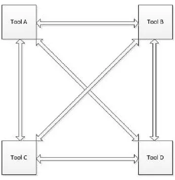
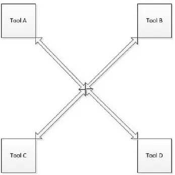
However, the environment builders will be more efficient and effective in integrating the tools. For every type of tool, they know what types of data they should expose and what types of data they need. What’s more, the limit to the number of interconnections between tools is limited to N, where N is the number of tools in the environment, as opposed to N(N-1)/2. This because all tools connect to the framework instead of each other. Therefore, the network of interconnections is a connected graph (Figure 4) rather than a complete graph (Figure 3).
16
Figure 4. Framework tool integration
Thus, at its very minimum, framework integration will reduce the number of interconnections between tools and consequently the amount of development effort to achieve them. There is however more merit to framework integration than simply the amount of development effort it requires, as we will see later on in this work.
17
3.2. Related work
In this section we discuss other tool integration efforts as found in the relevant tool integration literature. We take a look at the problems that are faced and attempt to establish a generalization. Note however that we only consider a certain class of tool integration efforts. To be more precise, we only consider efforts in which tools developed by different tool vendors are integrated together. The most prominent reason being that for a given situation we would like to be able to select the most adequate tool rather than the one that integrates with the other tools merely because it was developed by the same vendor. Thus circumventing vendor lock-in, i.e. having freedom of choice independent from the vendor, which is one of iFEST’s major goals.
3.2.1. Merlin ToolChain
The first tool integration effort involves a ‘configurable’ tool integration solution referred to as the Merlin ToolChain, as discussed in a paper by Pesola et al [7]. The Merlin ToolChain is, like iFEST, an effort aimed at the integration of embedded systems tools through framework integration.
The Merlin ToolChain divides tools up into four distinct categories. These are Requirements Management (RM), Test Management (TM), Configuration Management (CM) and Project Management (PM) tools.
Figure 5. Merlin ToolChain tool categories [7]
The Merlin ToolChain is based on Eclipse plug-ins that use the Merlin ‘master’ plug-in to connect to each other. The tools are integrated together by providing an interface compliant with one of the four interface definitions, implemented as an Eclipse plug-in. Every artifact in every tool has a unique identifier that allows for distinction.
18
Figure 6. Merlin ToolChain architecture [7]
A traceability plug-in uses the unique identifiers to create traces and stores them in a traceability database. The central idea of the architecture is that tools should merely implement the plug-in interface and there is no need for the master plug-in to know how a tool retrieves the data it exposes.
The paper moves on the discuss a prototype implementation of the framework, but does not discuss the specifics of the tool interfaces nor does it explicate what the problems faced in implementing them were. The work acknowledges that tools should be categorized and metamodels defined, like the ones in Figure 5. However, the metamodels are extremely simple and what is more, in the face of more complex metamodels the implementation of writing tool adaptors can be daunting, as we shall see in our discussion of the Wind Turbine industrial case study.
19
3.2.2. Fujaba Tool Suite
The second tool integration effort, the Fujaba Tool Suite, takes a deeper approach [8]. The Fujaba Tool Suite and its Fujaba Approach that integrates tools into the tool suite aim to achieve data integration at the metamodel level. That is, the tools are not just communicating by for instance sharing a GUI or
controlling each other’s functionalities, they communicate by speaking each other’s language or speaking a common language. We refer to this tool language as a metamodel. The metamodel is essentially the structure the models that a tool’s user is allowed to manipulate adheres to. Metamodels can for instance dictate the kind of attributes a requirement or component should have and what possible relationships to other artifacts it can have.
Ideally, we would like for the data we manipulate using tools to be consistent. That is, the data governed by the different tools in the tool chain retains the same picture of the system we are developing, or put more precisely; is semantically consistent. Not only does the process of assuring consistency for a given set of tools induce significant overhead, it makes it much more difficult to switch tools in the face of changing tool requirements. We discuss how the Fujaba Tool Suite and Approach dealt with these problems. For a general and more extensive discussion of tool integration and metamodeling, refer to section 3.3.
The attentive reader might be wondering why not all tool integration efforts deal with metamodel
integration. After all, metamodel integration is the only type of integration that would potentially integrate tools so tightly they simply do not allow inconsistencies to exist in the first place. The reason for this is that for metamodel integration to be possible, tools need to have facilities in place that allow access to their metamodels. The Fujaba Approach not only requires tools to provide access to their metamodels, but requires those metamodels to be extendable. This however is a rather advanced feature that only very recent tools possess, as having a flexible metamodel by implication requires the tool itself to be flexible also.
The Fujaba Approach and Tool Suite are focused around the tools being represented by plug-ins. Being a common mechanism for adding third-party components to existing products, the central idea is that dependencies are unidirectional. That is, a plug-in is dependent on the product or environment it extends, but not vice versa. Hence, the product can be compiled without any plug-ins that might exist. All tools are integrated into the Tool Suite using the plug-ins mechanism.
Two general plug-in based integration scenarios are considered in Fujaba:
20
In Figure 7, Tool B extends Tool A, implying there is a relationship requiring Tool B to be consistent with Tool A. Generally however, consistency is a bidirectional relationship. That is to say, Tool A is required to be consistent with Tool B but the inverse is also true. Especially if one considers an iterative development methodology, this surely is the case.
Figure 8. A third Tool 3 extending both Tool 1 and Tool 2 [8]
In Figure 8, Tools 1 and 2 are integrated by means of a third tool, Tool 3. This additional tool maintains the links between the two disjoint metamodels in Tools 1 and 2. Tool 3 requires both tools to compile, but this dependency does not hold the other way around.
A fundamental problem that arises for frameworks like this one (and is discussed in great detail in the work about Fujaba [8]) is the possibility to have bidirectional associations. Two classes in different metamodels may point to each other to indicate some bidirectional relationship, but this introduces a mutual dependency between the metamodels. As a result the extendable framework approach breaks. There are different ways however of having bidirectional relationships without having classes directly point to each other. One is to use attributes instead of references, but retaining consistency quickly becomes a problem. Even if we would somehow allow references, retaining consistency is still a problem because there is always an inverse reference that should be updated accordingly. To solve this latter problem, the work about Fujaba proposes to use public access methods that handle this updating with sophisticated mechanisms. However, the paper also offers solutions that eliminate explicit references completely.
These solutions are captured the Meta-Model Extension design pattern for metamodel extensions (Figure 7) and the Meta-Model Integration design pattern for metamodel integration (Figure 8) respectively. Both patterns maintain flexibility, because they ensure compile-time independence. However, because of this flexibility, the extensions to the existing models are quite clumsy. There cannot be bidirectional relationships for instance in the model extensions, because they introduce mutual compile-time dependencies. The paper’s proposal is to encapsulate the logic of extending the existing metamodels completely, as to ensure that they are correctly updated. While a fair approach, the downside is that for complex metamodel extensions, the logic that needs to be encapsulated is also complex, hence a burden is put on the developer.
21
3.3. Tool integration & metamodeling
We said that the goal of tool data integration is tool consistency. An entire subfield of research within the field tool integration is that of metamodeling and metamodel transformations. At the heart of this research is the hypothesis that every system development tool is based on a certain metamodel and that if we can somehow manage to integrate these metamodels we achieve tool consistency and therefore successful (data) integration. This can either be done by finding a way to transform models conforming to one metamodel to models conforming to the other, or defining a common metamodel. Metamodeling and its relation to tool integration are frequent topics in contemporary research, especially after the Object Management Group (OMG) issued a Request For Proposal (RFP) concerning Queries/Views/Transformations (QVT) in 2002.
Also, model transformations are an essential part of the iFEST IF. In the first of integration scenarios discussed in section 7.5 for instance, a tool called MDWorkbench [9] performs model transformations from HP-ALM to MATLAB Simulink [10] and vice versa. This section provides the reader with a basic understanding of the field.
Tool consistency is when tools agree on their view of the system and/or the development process. Or put more precisely, when the data they manipulate represents the same system or development process. The data in two different tools may be mutually exclusive, but where it overlaps, it should not be conflicting. For instance, one tool strictly managing functional requirements and another strictly managing non-functional requirements can be said to be consistent because their data does not overlap and therefore cannot be conflicting. However, two tools managing functional requirements are only said to be consistent if requirements do not contradict each other. Even if there are some requirements exclusive to each tool.
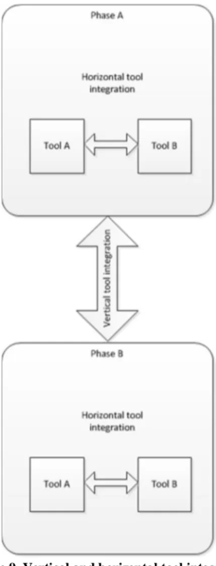
Moreover, the tools that are employed in the subsequent phase of the system development process should be consistent with regard to the tools in the previous one. However, as is the nature of system development, here the requirements on tool consistency are more strict. All data managed in the previous phase should be able to be traced to data in the next one. As an example, all software components in the design phase together should implement all the requirements in the requirements phase. We cannot allow for requirements that are not mapped to a component nor for components that do not implement any particular requirement. This type of consistency we will refer to as vertical consistency, whereas horizontal consistency involves tools used in the same phase (Figure 9). That being, if for example a requirements authoring tool is replaced by another, it should retain the same requirements model.
22
Figure 9. Vertical and horizontal tool integration
Perfect tool consistency in practice however, is difficult to achieve. For now disregarding issues such as the availability of APIs and appropriate documentation for tools, there is one problem more inherent to data integration. And that is that different tools rely on different metamodels. The data the tools manipulate is structured according to metamodel(s) and in order for successful data integration to be established, what we need is to integrate metadata. Adapted from a paper by Laurence Tratt [11] about model transformations and tool integration, let us sketch an example scenario to show why data integration can be so challenging.
23
Figure 10. Modeling languages with and without package inheritance [11]
In Figure 10, we defined metamodels representing two different modeling languages for simple class diagrams. The building blocks of class diagrams are packages, classes and associations. All of these are diagram elements. Figure 10 (a) is a modeling language that allows package inheritance while the modeling language in Figure 10 (b) does not. Package inheritance makes it possible to create more elaborate diagrams with less clutter. A package inherits all the classes from its parent package. Figure 11 (a) represents an example model of a company created using modeling language ML1 while Figure 11 (b) is the company model in modeling language ML2.
24
The company models in Figure 11 were created by hand. We intuitively merged the three packages Sales, Stock and Company into a single package. It would be much more convenient if we could somehow automate the transformation from one model to the other.
The first step is to make the models machine readable. One option is to use XML technology, describing the model textually. We could then try and build a program that parses the XML representation of the model in ML1 and produces a model in ML2. In the case of Figure 11, this would mean that the program looks for elements from inherited packages in ML1 models and brings them into the children directly. Under the assumption of imperative programming, there are two immediate problems however; if a package is specialized by two other packages then two copies of the classes in the parents will appear in the target model. Also, cycles in the model created by associations between two classes will cause the program to loop indefinitely. Surely, these problems are solvable, but only to a certain degree. To deal with cycles the program needs to remember which elements it has already seen, but for an arbitrarily complex model, the extra lines of code needed are arbitrarily complex.
It is apparent that in order to cope with the problems such as the ones just described, we need to keep adding an extensive amount of logic to the transformation program, for instance to keep track of which elements we have already transformed. This quickly leads to our program source code getting swamped and hard to comprehend. Tratt [11] goes as far as to argue that it is not sensible to write model transformations using a standard programming language, object-oriented (OO) or otherwise. Furthermore, so far we have only dealt with unidirectional stateless transformations. We are only able to transform from models in ML1 to ML2 but not vice versa and the transformations is not aware of which element in ML2 models map to which elements in ML1 models. In the general case however, a transformation is followed by small changes to the target model that eventually are fed back to the source model. This cycle keeps revolving until both models are deemed sufficient. Propagating changes back from the target model into the source model, while at the same time keeping track of which element maps to which element in both models, is a stateful bidirectional transformation. It is stateful because we keep track of elements mappings through tracing information. Retaining tracing information separately might intuitively be deemed unnecessary. Because arguably, one might say that a specific and unique source model should transform into a single specific and unique target model. Therefore, the reverse transformation of the target model into the source model should result in the original source model. In practice however, this bijectiveness of a model transformation usually does not hold.
What we need to look for, is some way to declare and perform transformations of models conforming to one metamodel to models conforming to another metamodel, but not using conventional programming paradigms. There are several different initiatives being undertaken, especially after the Object Management Group (OMG) issued a Request For Proposal (RFP) concerning Queries/Views/Transformations (QVT) in 2002. The goal of the RFP was to find a suitable standard for model transformations that fits within OMG’s already existing spectrum of standards related to Model-Driven Architecture (MDA) [12].
25
In the MDA approach to building software systems, the central idea is to keep models that relate to a system’s design separate from the models that represent the implementation. The former, Platform-Independent Models (PIM) are created using OMG standards such as the Unified Modeling Language (UML) and the Meta Object Facility (MOF) metamodeling language. These models can then be realized by any Platform-Specific Model (PSM) and implementation technology, such as CORBA, Java, XMI/XML, etc.
QVT is also one of OMG’s standards for Model Driven Architecture. QVT is a language that can define transformations upon models, in a declarative rather than an imperative way. The central idea is that in QVT one defines transformations from a PIM into various PSMs. We can argue that during development, only the PIM should ever be modified, essentially treating the transformation as a compilation. In practice however, it is necessary for developers to modify both source and target models. As a consequence, changes should be able to be propagated in both directions. Bidirectional transformations are a key requirement on QVT.
The QVT standard describes three languages for transformations: The Operational, Relations and Core languages. In QVT-Operational, it is possible to define unidirectional model transformations in an imperative way. Bidirectionality is achieved through manual consistency checking. In QVT-Relations we can define the relation between two models in a declarative way, allowing both unidirectional and bidirectional transformations. Core is a low level language that was created to be the target of QVT-Relations, but was never fully implemented. It has a simpler syntax than QVT-Relations though the transformations that are described using QVT-Core are more verbose. The objective however is to have QVT-Core be a language that can express any relationship between metamodels that is completely independent. That is, any model conforming to metamodel A can be transformed to a model conforming to metamodel B, without any inputs other than the two metamodels and the transformation expressed in QVT-Core. Also, the transformation back from B to A is entirely semantics preserving, without needing an additional input that contains the traces of the earlier A to B transformation. Which is not the case in QVT-Relations.
QVT-Core has never been fully implemented however, and to the knowledge of the author, neither has there ever been a full implementation of a semantics preserving transformation language that does not store traces explicitly. It almost goes without saying that a conceptual language like this would be of great value to any tool integration effort, including iFEST. After all, iFEST is using OSLC based metamodels that if integrated using a language such as QVT-Core could greatly reduce the development time of the tool adaptors.
26
4. The iFEST Tool Integration Framework (iFEST IF)
In a typical system development life cycle, different tools such as design tools, requirements authoring tools and testing tools are instantiated within their respective lifecycle phases, together forming a tool chain. These tools allow the creation and manipulation of relevant artifacts, based on underlying metamodels. These artifacts can be of various kinds. In the requirements engineering phase they can generally expected to be requirements. In the software design phase they can generally be expected to be software components. And so forth. However, these are merely examples and there are many more different flavors of artifacts.
As the life cycle progresses from one phase to the other, the ultimate goal of the entire life cycle is to retain consistency. Without going into a formal definition of consistency, it is not difficult to get an intuitive feel of what this consistency encompasses. A requirement defined in the requirements engineering phase should be captured by one or multiple software components in the software design phase. Respectively, all software components should be present as testing artifacts in the software testing phase.
If all artifacts in a certain phase are entirely traceable to artifacts in all the other phases, then from the standpoint of the engineer the system is flawless, as the artifacts across the different lifecycle phases are entirely consistent, meaning all requirements have been implemented, and all system shortcomings can be blamed on inadequate requirements.
But this kind of traceability is far from trivial to achieve. Not only do tools rely on different metamodels and do these metamodels in general differ greatly, there are many different tools being used in the industry today. Some tools provide APIs, some do not, some provide access to their local repositories and only a very small number of tools is open source.
The varying nature of tools makes tool integration a very challenging endeavor, with many different problems to solve. What’s more, there is an ever growing market demand for more powerful systems with a smaller and smaller size. The result is an ever increasing complexity of systems as requirements become more constrained. It is no longer an option to maintain subpar performance or have a device be larger than absolutely necessary. With increasing system complexity however comes an increasing complexity of the tools we use to design those very systems. Especially in the embedded systems range of tools available today, many are unable to cope with this increasing complexity, let alone provide adequate tool integration facilities. An increase in development costs, followed by increasing costs of poor quality is the result.
To develop a framework that will allow for the integration of embedded systems tools, in April 2010 the iFEST (industrial Framework for Embedded Systems Tools) project [3] was initiated. With 8 countries and 21 organizations participating directly and a duration of 3 years it is one of the largest tool integration research initiatives initiated to date.
In this chapter we discuss the iFEST project goals (4.1), iFEST key concepts (4.2), iFEST architecture (4.3) and make a comparison to other tool integration efforts (4.4).
27
4.1. Project goals
The iFEST project is a project aimed at specifying and developing a tool integration framework, the iFEST tool Integration Framework or iFEST IF, for hardware-software co-design of heterogeneous and multi-core embedded systems. The iFEST IF will allow tools to be readily placed within the tool chain. The framework will enable the tools to exchange data automatically, ideally eliminating the need for engineers to analogously make the transition from a tool in one life cycle phase to a tool in another. This is expected to significantly reduce the time-to-market of the system under development, reduce development costs and increase the quality of the overall system design. Also, it deals with the issues of tool lock-in and tool obsolescence, which are both less likely to occur as tools are more easily replaced. Switching costs can be lowered, allowing for a choice of the most adequate tool and its supplier rather than the one that is most attractive one when viewed from a commercial perspective.
The iFEST IF is validated by a number of industrial case studies carried out by the different iFEST partners.
Two flavors of prototypical tool chains have been defined. The two application domains are data streaming and industrial control. Industrial case studies should be within one of these two application domains and demonstrate a potential reduction of development costs (1), time-to-market (2) and cost of poor quality (3).
The validation of the iFEST IF through industrial case studies focuses on tools that fit within the V-model [13]
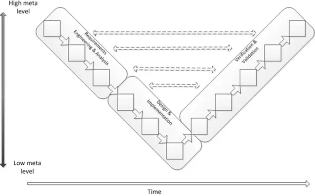
development methodology. Having a rather broad definition, the V-model generally comes down to having two separate, converging “streams” of lifecycle activities or phases, together constituting the resemblance of a letter “V”. The activities in the left-hand arm of the V are the activities that are concerned with the actual inception of the artifacts that will together constitute the system being developed. The activities in the right-hand arm deal with the verification and validation of the activities on the left-hand side. Descending down the arms we move from activities dealing with artifacts on a higher meta level, down to tools dealing with more and more specific system details, to finally end up at implementation tools at the bottom of the V, where the streams come together. Although a lot of different editions of the V-model can be found in the literature, we categorize three different flavors of tools, depicted in Figure 12.
28
Figure 12. V-model
As we can see, the activities (depicted by the little squares) descend down the V, crossing lower and lower meta levels, to finally end up in a single final activity in which the system is fully developed. The dashed arrows across the V resemble the fact that activities in the left-hand arm always have a counterpart in the right-hand arm, that validates and verifies the activity outputs and feeds back.
The upper side left hand stream is defined as Requirements Engineering & Analysis, or RE&A for short. In RE&A we are concerned with defining requirements for the system we are building, both high and low level, in essence providing a blueprint on which the implementation should be based. The requirements are a reflection of what the client stakeholder wishes the system to do.
Design & Implementation, or D&I, is the set of phases in which we define and develop components that implement the requirements, in essence mapping those requirements onto implementation artifacts. These artifacts can be abstract, like software components, or physical, like an actual server on which software is deployed.
Verification & Validation finally is where we establish whether the requirements and system components match and are non-conflicting. Testing is an important aspect of V&V, ensuring components are of an adequate quality and behave as expected. Usually, within the V-model methodology there are additional maintenance activities after V&V, but within iFEST these are not considered.
The essence of the iFEST IF comes down to traceability between (artifacts in) the different phases. The horizontal arrows in between the two arms indicate a traceability relationship between the development artifacts and tests. That is to say, every requirement or system component is traceable to one or multiple tests in the V&V activities. In addition, the arrows leading back up the arms indicate a traceability relationship between the activities as they progress from the definition of requirements to design to
29
implementation. Every requirement should be traceable to one or more logical components, whereas every logical component should be traceable to one or more actual system components.
The iFEST IF is aiming to show benefits for tools in all of the three categories of lifecycle phases. Within Requirements Engineering & Analysis it will show an increased linkage of textual requirements to executable models and simulations. It will prevent loss of information and it will provide increased support for traceability to test cases and early validation of the requirements.
With respect to D&I the iFEST IF is expected to close the gap between the high level design of the system and its actual implementation components. Additionally, it will require less effort to replace propietary tools and/or formats. This results in a more efficient design space exploration and more effective testing, simulation and evaluation opportunities.
As for V&V, requirements and model based verification will require less effort and become available as viable options earlier on the in the lifecycle. Furthermore, we are able to detect flaws and faults in a more timely fashion, leading to a reduced development time and cost.
Every tool used in the iFEST IF industrial case studies belongs to one of the three categories. Furthermore, every category has been given a definition in terms of process patterns, transformations and tool metamodels. HP-ALM\RM belongs to the category of Requirements Engineering & Analysis.
30
4.2. iFEST Key Concepts
In this section we take a look at the most important concepts that constitute the iFEST Tool Integration framework. Figure 13 provides a depiction of the metamodel that was defined at the start of the project.
Figure 13. iFEST key concepts
Starting in the upper right corner, we find the concept of a tool chain. A tool chain is a set of tools and their corresponding tool adaptors that together form an integrated development environment. The tool chain may employ an integration platform that is typically provided by an external supplier. Integrated tools use tool adaptors to expose the artifacts in their tool instances in a common format. The adaptors comply to iFEST specifications, guidelines and principles. The tool adaptor specification consists of data and service specifications. The data specification provides a metamodel of the adaptor, whereas the service specification defines the tool adaptor in terms of provided and required services.
In its simplest terms, a tool adaptor provides a way for a systems tool, or as matter of fact any system component, to connect with other tools. A metaphor to an electrical adaptor is well suited to explain. Just like an electrical adaptor transforms one current to another because the machine it is connected to only supports a certain current, so does a tool adaptor provide the correct current or data formats for a given tool. Providing the right current however, is a far from trivial matter. Practicalities such as the availability of APIs aside, the transformation from one data format to another can be arbitrarily complex or even impossible to fully implement (i.e. retaining semantics completely). The tool adaptor is the software component that for a given tool implements this transformation from its native metamodel and data format and makes it available to other tools in another metamodel and data format.
31
Lastly, the iFEST tool Integration Framework provides a technological space. That is, the technology on which the implementation will rely. This includes but is not limited to data formats, communication protocols and standards. The chosen technology in the case of iFEST is OSLC, but conceptually any other suitable technology could serve.
Figure 14. Example tool chain
In Figure 14 we see an example tool chain as it could look like within the iFEST IF. Tools, whether they are specific to a lifecycle phase – engineering tools – or cross-domain are connected to the framework and its technological space by means of a tool adaptor. The adaptor is defined in terms of required and provided services. The iFEST IF does not dictate in this respect. In addition to the tool adaptors for specific engineering tools, in the figure we also find traceability tools and process tools along with their respective adaptors. Together with a traceability and/or a process tool, a tool can form what is known as an integration platform. The traceability tools provides the facilities that allow for the creation of traces between artifacts in two different tools, whereas the process tool retrieves information it needs from the other tools to manage the development process, if any.
32
4.3. iFEST Architecture
In the framework, we find the tool instances, the tool adaptors, the repository (or Configuration Management System – CMS) and the service orchestrator. Tool instances represent the running instances of the tools used within the tool chains.
Examples of tools include HP-ALM, Simulink, Enterprise Architect (EA) and IRQA. The tool adaptors are the means through which the tool instances communicate with the other participants in the framework. Paramount is that the adaptors expose tool data through common format. The IF repository is the entity in the framework that for every relevant tool stores its so-called IF versions. This is to say that for every tool in the tool chain, there exists a separate folder on the IF repository that contains the published versions of its model(s), either in OSLC, ReqIF [14] – Requirements Interchange Format, a recent standard for denoting requirements in XML -, some other formats or a combination of the three. The orchestrator is the final entity in the framework and provides general services to the other entities. The tool adaptors can for instance register themselves with the orchestrator, in order to receive notifications about newly published IF versions of models from tools they are interested in.
33
The IF repository is a central storage facility that will maintain the models for every tool separately. Every tool is assigned its own unique folder, whereas an “IF Data” folder contains data relevant to the entire tool chain, such as traces between artifacts.
As we said, the repository will contain the so-called IF versions of the data contained in the tools. As a tool user is using his or her respective tool, the data that is being manipulated progresses through different versions. However, not all these versions include major changes. Therefore, only when the tool user publishes is a new IF version created. This is depicted in Figure 16.
Figure 16. IF versions
As we can see, a tool might have its own version management system that is entirely decoupled from the version management system of the entire tool chain. Not every minor change is relevant to enough to publish a new IF version. For this reason, a tool adaptor has direct access to its own folder on the IF repository, but the other tool adaptors access this folder through the framework.
34
4.4. How is iFEST different from other tool integration efforts?
iFEST is a framework meant to integrate tools that are used in the development of multi-core and heterogeneous embedded systems. iFEST takes a framework integration approach by building tool adaptors for the lifecycle tools it means to integrate and then have them communicate through a common data format. The central idea is that the lifecycle tools in the tool chain manipulate shared concepts and as such, the lifecycle tools should act in a coherent way. Two engineers working in the same domain with different lifecycle tools should be manipulating the same artifacts to avoid inconsistencies. Figure 17 visualizes the iFEST approach.
35
Ideally, the transition from one activity in the lifecycle to another is seamless, shown on the left-hand side of Figure 17. The tools employed share a common metamodel and communication between them is completely transparent. But this is far from today’s practical reality. In a lot of cases the transition between activities in tools is manual or semi-automatic at best. An engineer looks at the output of the activities up the tool chain and produces an intuitive mapping of the models to the engineer’s own domain. A designer creates components that implement the requirements specified by the requirements engineer, but whether or not all requirements have been addressed sufficiently is established mostly by hand.
In the iFEST Tool Integration framework, this transition is intended to be automated. The realization that tools in the tool chain have shared concepts makes it possible for them to speak a common language and as a result, (semi-) automatically transform models and validate their consistency. To integrate lifecycle tools in a tool chain using the iFEST framework, some development effort is required. The effort consists mainly of specifying and implementing the tool adaptors. The tool adaptor is a generally small piece of software that acts as a bridge or interface between the lifecycle tool and the framework. For every lifecycle tool a tool adaptor needs to be developed, but as we will see in chapter 6, a fairly large chunk of functionality is shared among adaptors and the amount of unique development effort is limited if we exploit this property through the use of SDKs and the like.
Moreover, the iFEST framework will provide definitions of process flows describing the set of activities (and their respective tools) to be performed.
These scenarios describe:
How tools should be chained together. How tool data is exchanged and transformed. How tools are to be invoked.
iFEST aims to use the specifications of the Open Services for Lifecycle Collaboration (OSLC) [2] initiative. Being a fairly young initiative, these specifications are meant to standardize the way lifecycle tools share data, but the implementation efforts performed thus far at the time of writing are not many, nor are the specifications mature. Therefore, iFEST will try to adhere to OSLC as much as possible, but deviate where necessary. For instance, as we will see later on, OSLC’s capabilities to represent relevant models in the Wind Turbine industrial case study were deemed too verbose for transformations between HP-ALM and MATLAB Simulink, so a different solution was found.
36
The tools iFEST is targeting are focused around the design and implementation of heterogeneous, multi-core embedded systems. Because of the specific nature of these tools, their integration also requires special treatment.
Embedded systems are systems with a very specific application within a larger system, in a lot of cases intended to monitor or control some physical process under real-time constraints. The codebase of embedded systems is generally kept relatively small, as memory and processing power available may be limited. Exception handling and general fault tolerance is pruned. Also, as embedded systems often operate under real-time constraints, they are developed to be as efficient as possible.
However, the efficiency of these embedded systems comes at a price. Parallelization increases the system’s complexity, while fault tolerance is already being sacrificed. In other words, the risk of faulty behavior is bigger as is the risk of that faulty behavior causing a complete system failure.
Because of these increased risks, the modeling efforts performed in an embedded systems development project are of a more formal nature. Models of Computation (MoC) are employed to analyze algorithmic behavior. This includes analysis of execution time and memory use, but also behavior of individual variables and the operations performed on these variables. Examples of MoCs include Communicating Sequential Processes (CSP) by Hoare [15] and Petri nets by Petri [16]. They allow mathematical reasoning about the system and therein constitute a way to formally prove the system’s validity.
What’s more, The tools used in the iFEST IF manipulate models of a high complexity, typically containing thousands of artifacts. For requirements authoring tools there are, in addition to having functional and non-functional requirements, structural requirements that specify logical or actual components to be used in the system design tools. It is paramount that these requirements be transformed and traced accurately. It, in our case, encompassed additions to both the tool and tool adaptor, as will be discussed in chapter 6. The structural requirements are primarily logical blocks that carry out a specific function within the system. The blocks are wired together through the use of ports, which in turn can be grouped by interfaces.
The reason it was decided to manage these structural requirements within requirements authoring tools also, is because it allows us to establish traceability relationships from functional requirements to structural requirements within the same tool. Generally, the requirements engineer alongside defining the functional requirements also conceives a general system architecture, that is later exchanged to an actual D&I tool. The designer refines the architecture, after which the it is reimported into the requirements tool. In summary, iFEST Tool Integration framework is subject to very specific requirements pertaining to the tool chain and process, as well as the tools themselves and the models they manipulate. In chapter 6 we will see how this specificity influenced the development of the HP-ALM/OSLC adaptor.
37
5. Open Services for Lifecycle Collaboration (OSLC)
As the iFEST project aims to use OSLC specifications and standards as part of the iFEST Tool Integration framework, in this chapter we introduce the reader to the general principles and concepts of OSLC (5.1). We also discuss how OSLC achieves tool integration (5.2) and how tool adaptors are implemented using OSLC (5.3).
5.1. General concepts
Open Services for Lifecycle Collaboration (OSLC) is a community of software developers, researchers and software professionals that was founded to create a set of specifications that aim to standardize the way software lifecycle tools share data. The specifications produced by the OSLC initiative are rapidly developing and its members include some of the world’s leading software companies and research institutes.
All OSLC specifications are based on or around the concept of Web services. That is, computer programs communicating over a network in a RESTful way, in most cases using HTTP as
a protocol and RDF/XML as a way to represent the data that is being sent and received. Their communication is bound by what is known as a service contract, which in essence is a description of the functions a certain service implements. OSLC Web services are based on W3C’s concept of Linked Data [17]. Including, but not limited to a set of 4 simple rules :
Use URIs as names for things.
Use HTTP URIs so that people can look up those names.
When someone looks up a URI, provide useful information, using the standards (RDF*, SPARQL).
Include links to other URIs, so that they can discover more things. (sic)
The OSLC Web services enable integration of tools, products and services that support Product Lifecycle Management (PLM) and Application Lifecycle Management (ALM). Each type of tool, product or service has its own group specification, alongside the existence of a core specification, on which all the others are based. Examples of these groups include Requirements Management (RM), Change Management (CM) and Quality Management (QM).
The core specification describes the primary techniques and patterns for integration.
Central to the OSLC specifications are Services, Resources and related concepts. All artifacts in the lifecycle - like requirements, tests, defects, etc. - are resources that can be accessed via HTTP using the Linked Data principles described above. I.e. every resource has a URI and links to other resources using URI’s. Each resource is required to provide an RDF representation, but an arbitrary number of other representations is allowed alongside RDF. Examples include HTML and JSON, an XML format that allows for serialization of Java objects.
![Figure 1. Dimensions of tool integration [1]](https://thumb-eu.123doks.com/thumbv2/5dokorg/4922644.135606/14.918.173.762.108.572/figure-dimensions-of-tool-integration.webp)
![Figure 2. Tool relationships and their properties [1]](https://thumb-eu.123doks.com/thumbv2/5dokorg/4922644.135606/15.918.145.779.302.762/figure-tool-relationships-properties.webp)
![Figure 5. Merlin ToolChain tool categories [7]](https://thumb-eu.123doks.com/thumbv2/5dokorg/4922644.135606/18.918.148.775.544.892/figure-merlin-toolchain-tool-categories.webp)
![Figure 6. Merlin ToolChain architecture [7]](https://thumb-eu.123doks.com/thumbv2/5dokorg/4922644.135606/19.918.146.773.109.467/figure-merlin-toolchain-architecture.webp)
![Figure 8. A third Tool 3 extending both Tool 1 and Tool 2 [8]](https://thumb-eu.123doks.com/thumbv2/5dokorg/4922644.135606/21.918.210.704.264.467/figure-tool-extending-tool-tool.webp)
![Figure 10. Modeling languages with and without package inheritance [11]](https://thumb-eu.123doks.com/thumbv2/5dokorg/4922644.135606/24.918.309.611.117.420/figure-modeling-languages-package-inheritance.webp)