Hierarchical server-based communication with
switched Ethernet
Farahnaz Yekeh
Master in Software Engineering
Department of IDT M¨
alardalen University, V¨
aster˚
as, Sweden
fyh08001@student.mdh.se
Supervisor: Thomas Nolte
External supervisor: Luis Almeida
Contents
1 Introduction 5
1.1 Problem Formulation . . . 6
1.2 Main Challenges . . . 6
1.3 Problem Description . . . 6
1.4 Outline of the Thesis . . . 9
2 Background Knowledge 10 2.1 Ethernet . . . 10 2.2 Ethernet Switch . . . 10 2.3 Real-Time Ethernet . . . 11 2.4 Master-Slave (MS) Techniques . . . 14 2.5 FTT-Ethernet . . . 16
2.6 FTT-enabled Ethernet Switch . . . 17
2.7 Server-Based Real-Time Communication . . . 19
2.8 Real-Time Communication . . . 20
2.9 Protocol . . . 21
2.9.1 EDF Scheduled Switch . . . 21
2.9.2 EtheReal . . . 23
2.10 Summary . . . 25
3 Different Network Architectures 26 3.1 One FTT-Enabled Switch on Top, Multiple COTS Switches . . . 26
3.2 FTT-Enabled Switches on Leafs, Multiple COTS Switches . . . . 27
3.3 Multiple FTT-Enabled Switches with Gateways . . . 28
3.4 Multiple FTT-Enabled Switches without Gateways . . . 29
3.5 Selected Architecture . . . 30
4 Protocol 31 4.1 Designed Protocol for our Problem . . . 31
4.1.1 Description . . . 31
4.2 Protocol Model . . . 34
4.2.1 Modeling in Uppaal . . . 34
4.2.2 Models of Sender, Receiver and Switch . . . 34
4.2.3 Supporting Concurrent Multiple Requests . . . 40
4.2.4 Seudocode of the Process in the Protocol . . . 41
4.2.5 Diagrams of the State Machine’s Behavior . . . 42
4.3 Summary . . . 45
5 Timing Analysis 45 5.1 Asynchronous Messages Analysis . . . 45
5.1.1 Without Gateways . . . 45
5.1.2 With Gateways . . . 48
List of Figures
1 Hierarchical Switches . . . 7
2 Possible approaches for building real-time Ethernet [11] . . . 12
3 Internal architecture of a Switch [21] . . . 14
4 FTT architecture [24] . . . 17
5 FTT-enabled Ethernet switch [29] . . . 18
6 Layers and output queues [12] . . . 21
7 Architecture of Network [12] . . . 22
8 Reat-Time (RT) Channel Establishment [12] . . . 23
9 EtheReal, RT connection setup [31] . . . 24
10 One FTT-enabled Switch on Top and Multiple COTS switches . 27 11 FTT-enabled switches on Leafs and Multiple COTS switches . . 28
12 Multiple FTT-enabled switches with Gateways . . . 29
13 Multiple FTT-enabled switches without Gateways . . . 30
14 RT Channel establishment . . . 31
15 Sender and Receiver models in Uppaal . . . 35
16 Examples . . . 36
17 Switch Model in Uppaal . . . 37
18 Request Reject sample 1 Diagram in Uppaal . . . 42
19 Request Reject sample 2 Diagram in Uppaal . . . 43
20 Request Success Diagram in Uppaal . . . 44
21 Best case Example, without any Gateway . . . 46
22 Worst case Example, without any Gateway . . . 47
23 Best case Example, with Gateways . . . 48
Abstract
Server-based architectures have recently generated more interests and are cur-rently considered for usage for communication in networks. In parallel, switched Ethernet technology has been widely adopted and used in lots of networked systems. Current requirements of networks for supporting real-time guaran-tees while being flexible at the same time have made the network designers to consider addition of some features to common switches. The FTT-Enabled Eth-ernet switch is a switch that has been developed to support the FTT (Flexible Time Triggered) paradigm. Recently, servers have been added in these types of switches in order to efficiently manage their allocated bandwidth to different types of messages.
A hierarchical network of Ethernet switches might be designed in different ways according to the overall goals and properties of the network. In this thesis, after a study on different design solutions, an architecture has been proposed based on FTT-enabled switches, motivated by their support of real-time constraints and server-based communication features. After having created the architecture, a protocol for bandwidth reservation for this hierarchically composed Ethernet switch architecture is developed. Behavior of the designed protocol is described in detail and it has been modeled using Uppaal. Moreover, the temporal be-havior (timing) of the network is presented.
The first part of the thesis gives a description of the problem formulation, fol-lowed by an overview of related works. Possible architectures for designing a hierarchical network are discussed in Chapter 3. Solutions to the problem, behavior of the proposed protocol, and its model are presented in Chapter 4. Timing analysis of the designed protocol is presented in Chapter 5. Finally summary, conclusions and future works conclude the thesis.
Keywords: Ethernet, switched Ethernet, real-time communication, real-time analysis, server-based scheduling, and real-time channels.
1
Introduction
Nowadays, development of embedded systems for different purposes is widely increased. Moreover, the communication between these systems according to their requirements is different from one system to another. Current require-ments of networks for supporting real-time guarantees while at the same time being flexible have made the network designers to consider additional features to current switches in the network.
Ethernet has established itself as the dominant local area networking pro-tocol [10]. Main factors that favor the use of this propro-tocol are [9]: ”cheap silicon available, easy integration with Internet, clear path for future expand-ability, and compatibility with networks used at higher layers on the factory structure”. Therefore, several works have been done to use Ethernet in time-constrained communications. Examples of the methods that have been used to support deterministic message transmission over Ethernet have been modifica-tion of the Medium Control (MAC) layer (e.g. [17]) and adding sub-layers over the Ethernet layer (e.g. [32]). Then, after invention of switched Ethernet and absence of collisions, a new set of works on having time-constraint communi-cation has been started. Different techniques such as distributed solutions and Master/Slave approaches [26] have also been presented for supporting timing constraints.
Recently, the FTT-enabled Ethernet switch, a switch that supports the FTT (Flexible Time Triggered) paradigm has been introduced. It has a centralized scheduling mechanism providing flexible real-time communication, supporting dynamic changes in the communication requirements with timing guarantees [18]. Then servers have been added in these types of switches in order to effi-ciently manage their allocated bandwidth to different types of messages.[24].
In this thesis, after a study on different architectures for designing a hier-archical network of switched Ethernet solutions, an architecture has been pro-posed. The selected architecture is a network in which all switches are FTT-enabled. The selected choice is motivated by its support of real-time constraints and server-based communication features.
After having the created architecture, a protocol for bandwidth reservation in this network is developed. The behavior of the designed protocol is described in detail and it has been modeled using Uppaal. In order to model the protocol, all elements of the network including sender and receiver hosts and switches are modeled. Moreover, the temporal behavior (timing) of the network is presented.
1.1
Problem Formulation
The thesis title is ”Hierarchical server-based communication with switched Ethernet” and discusses different architectures of a hierarchical switched Eth-ernets network. Moreover, network’s behavior and a protocol for communica-tions between devices in the network have been presented.
The goal of the thesis is to develop a protocol for bandwidth reservation on hierarchically composed Ethernet switches, check behavior of the proposed protocol and present some kind of analysis on the result.
1.2
Main Challenges
The following items are main challenges in the thesis.
* Review the state of the art in the area of real-time communications on switched Ethernet.
* Study the switched Ethernet approach developed by Luis and Nolte, and think on how this can be done (extended) hierarchically; what are the implications of making a hierarchical architecture? Will there be any problems? What are the benefits?
* Once a hierarchical architecture is chosen, develop a protocol for band-width reservation for this hierarchically composed Ethernet switch archi-tecture; users should be able to setup guaranteed bandwidth channels on this architecture (study of relevant related work).
* Develop some kind of graphical tool where the network architecture can be edited and the protocol could be configured, and simulated to get performance data.
* Develop some kind of simpler (real-time) analysis that can be used to complement the simulation performance data.
1.3
Problem Description
The problem is how to create, define protocols, and evaluate behavior of a network which should support real-time and non-real-time traffics and consists of multiple switches connected hierarchically. The switches might be FTT-enabled Ethernet switches, COTS switches or a combination of both.
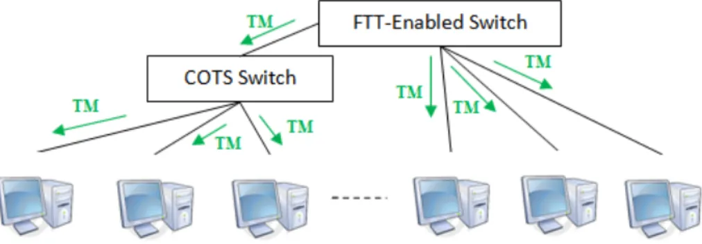
Pervious studies which are discussed in the ”Background Knowledge” chap-ter, present solutions for supporting real-time and non-real-time traffics in net-works consisting of Ethernet switches and FTT-enabled Ethernet switches. In the thesis, instead of having just one switch in the network, the network con-sists of several switches connected hierarchically. This makes the problem a bit more complicated. Moreover, some other features should be considered and a protocol for communication between switches should be designed. Therefore,
Figure 1: Hierarchical Switches
timing behavior and a protocol for a network which supports real-time traffic and server-based communication, is studied and evaluated.
Ethernet is one of the most important networking technologies and has ap-plied for the network in which switched Ethernets are connected hierarchically. Figure 1 shows an example of a network in which switches are connected to each other and end nodes (end hosts) are connected to the switches. The end nodes send real-time (periodic and sporadic) and non-real-time traffic to the network and the network is responsible to guarantee the temporal behavior of the net-work. Therefore, this thesis is defined to specify behavior of the switches, their intermediate protocols and their messaging mechanism, in a way that fulfills the timing constraints of the network. Then an evaluation of networks behavior is presented.
Questions about the Problem and the Answers
The following questions are different aspects of the problem which are considered before starting the thesis and the answers have been completed during doing the thesis.
* How these switched Ethernet can be connected?
The switches which are used are FTT-enabled Ethernet switches. These switches are connected hierarchically and contain servers in their inter-nal design that support server-based communication for different types of traffic.
* Are there any limitation on the number of switches, the depth of the network, the number of the end nodes and their locations in the network?
No. A mechanism for checking possibility to send data from a source to a destination is proposed. In the proposed mechanism, there is no difference
in the number of switches, length, depth and position of the end nodes. If all devices in the path accept the requested timing and bandwidth for sending packets, the requested data transmission will be accepted. It is obvious that in case of having a lot of devices in the network, the per-formance is reduced and the number of rejected requests will be increased in comparison of having a network with less traffic.
* How can they communicate with each other and how does the protocol work?
A protocol for communication between switches has been proposed and described in details in section ”Protocol Description” of Chapter 4. The basis of the proposed protocol is sending a request for establishing a real-time channel from a source to a destination. Then packets will be sent through the channel if all switches in the path accept the channel. After finishing the transmission of packets, the channel will be released. * How does it guarantee that real-time features are fulfilled (in
both synchronous and a-synchronous messages)?
Real-time guarantees for asynchronous messages are checked according to availability of the corresponding servers of the switches in the path, their pre-reservation and allocation for establishing a channel request. In this network, synchronous messages that are sent to other branches of the network might be considered as asynchronous messages as well.
* Are distributed solutions or master-multiple slaves have been proposed? Why?
Switches that are used in the network are FTT-enabled Ethernet switches which use trigger messages (TM) in themselves. So neither separate dis-tributed solution nor master-multiple slave mechanism is proposed in the network.
* How are messages sent and received in the switches?
Messages are sent and received similar to the normal packets in an Eth-ernet network. The only difference is in their type and data that are processed in the switches.
* How loop in the networks is considered in the proposed protocol and solution?
The proposed solution is a network of FTT-enabled Ethernet switches which works similar to common switches. Their difference is in their ad-mission control and internal architecture in order to support real-time traffics. All switching and routing mechanisms are the same as what is done in common switches. Therefore, similar to COTS switches, in the proposed network, spanning tree is used to avoid loops in the network.
* Bandwidth limitations in each port, how is calculated?
There are a number of servers in each switch that have specific capacity and period. These servers control bandwidth reservation by checking usage of a maximum bandwidth equal to the capacity in each period, and limiting bandwidth usage. Each port of a switch has a queue of these servers to perform bandwidth limitation mechanism.
* How is bandwidth limitations assigned in a switch? How does a switch guarantee real-time deadlines?
Different types of servers in a switch and the admission control of the switch checks and guarantees timing and deadlines of messages.
* Which techniques have been used to reduce the overhead of the network (e.g. protocol overhead) in order to use the bandwidth of the network in an optimized way?
When a resource is pre-reserved or allocated for a request, it will be used only for that request. So, there is no possibility to release these types of resources to any other higher priority request. In case of having this possibility, more messages should have been sent for announcing the occur change of the current event. Therefore, more bandwidth will be used in the network . More optimizations might be done by changing the protocol to acts more heuristic.
* How should it be evaluated?
Evaluation and behavior of the network are shown by modeling the pro-posed protocol in Uppaal which is described in section ”Protocol model”.
1.4
Outline of the Thesis
The rest of this thesis is divided into five chapters that are summarized as follow: • Chapter 2 gives related background knowledge and related works in the area of the thesis problem. Ethernet, Time Ethernet, Switched Real-Time Ethernet, Server-based mechanisms and two examples of Real-Real-Time communication protocols are described in this chapter.
• Possible architectures for designing a hierarchical network are discussed in Chapter 3. Then the selected architecture and the reasons for choosing this architecture are described in this chapter.
• In Chapter 4, a solution to the problem is proposed. Then it continues by modeling the proposed solution and showing its behavior.
• Timing analysis of the designed solution is presented in Chapter 5. • Finally, the thesis is concluded in Chapter 6 with a summary of the
2
Background Knowledge
2.1
Ethernet
Ethernet is the dominant local area networking in home and office environments. It is because of its cheap price, fast speed and easiness to be installed. Therefore nowadays most computerized equipments have built-in Ethernet interfaces [10]. Ethernet invented in the 1970s at the Xero’s Palo Alto Research Center and its first IEEE standard on 802.3 published in 1985 [1]. Ethernet’s initial purpose was connecting a personal computer to a laser printer. Since 1985, Ethernet has improved in different aspects such as topology and transmission speed. In the former aspect, it changes from a bus topology to a more structured and fault-tolerant approach based on a star or tree [3, 2]. Concerning to the latter aspect, its speed from 1Mb/s in 1987 [10]has increased to 1 Gb/s [5] and 10 Gb/s [6].
Ethernet protocols have kept two fundamental properties: a) existence of a single collision domain (broadcast domain), and b) the Carrier Sense Multiple Access with Collision Detection (CSMA/CD) arbitration. Conventional Ether-net has the problem of capture effect, which means that a transmission may be canceled after reaching the maximum number of retries, even in the absence of error in the link. [10, 18]
According to CSMA/CD, a network interface card (NIC) transmits data to bus while the bus is free. Then it senses the bus for a time slot to check collision. If a collision occurs, it stops sending data and waits for a random time, then retransmit the data. Therefore, this nondeterministic feature of CSMA/CD arbitration mechanism is an obstacle for supporting real-time application [18].
2.2
Ethernet Switch
Hub-based architecture developed in year 1987. In this architecture, a hub acts as an n-port repeater and regenerates signals received from one port and transmits them to all other ports. In this topology each station is connected via point-to-point twisted pair cable to a hub [10].
In 1997, hub replaced by a MAC bridge, called an Ethernet switch. The switch sends the regenerated data only to the destination link or the link that reaches to the destination [4].
Hub-based solutions are limited to half-duplex because of retransmitting what has received to all of its connected stations. On the other hand switch-based architectures are full duplex operations on each cable without any col-lision. The reasons of having no collision are their point-to-point connections from one station to a switch and vice-versa or from a switch to another switch, and the policy of queuing while transmitting data on output ports.
Bridges forward information to their ports according to their knowledge of network. Their knowledge is updated when they receive data from their ports and multicast frames to other ports. In order to disable redundant links, they use spanning tree algorithm. [4]
2.3
Real-Time Ethernet
Ethernet is not considered as a suitable solution to support industrial and real-time communications. The reason is its non-deterministic characteristic, in its random selection for sending messages that are ready to be transmitted from different stations. Also it does not guarantee real-time features such as maximum transfer delay, jitter in transmissions and available bandwidth [10].
Therefore solutions in order to provide deterministic behavior presented in later developed protocols such as Token Bus and Token Ring, but they were too limited mainly in terms of throughput in comparison to available non-real time networks such as Ethernet or CAN [10].
Later it was need to upgrade existing systems to higher speed and perfor-mance ones. In some cases due to limitations in the principle of operation, this might not be feasible. Also the cost of the new development for these upgrades to a small market becomes an obstacle. On the other hand Ethernet and the as-sociated protocols IP, TCP and UDP become so widely used that its costs have become drastically lowered. Ethernet’s speed increased and therefore a number of vendors offer industrial communication solutions based on off-the-shelf Eth-ernet ICs with various modifications on the protocols to improve predictability [10].
Developing of switched Ethernet increased global throughput and provided parallel switching paths. It also segmented the network and created isolated domains. As a result non-deterministic features of original shared Ethernet reduced.
However, COTS Ethernet switches still suffer from a few drawbacks that affect negatively their real-time communication capabilities. For example, over-flow in port queues, priority levels and virtual LANs, and a few number of priorities for any kind of priority-based scheduling. Inside the switches, there are extra latencies and jitters for interpreting frame addresses because switches need to process addresses (and different internal architectural solutions). [24] Possible Structures for Real-Time Ethernet
Standard Ethernet is not developed for supporting real-time requirements. Thefore, there are different propositions to modify Ethernet which are done by re-search academy and market. All the solutions are based on the following possible structures which are presented in this chapter. Three possible structures have presented for real-time Ethernet by Max Felser at [11]. These approaches that are shown in Figure 2 are as follows:
• Keeps TCP/UDP/IP protocols unchanged and focus on all real-time changing in the top layer
Transparent communication over network boundaries is possible without changing TCP/UDP/IP protocol stack. Though handling this communi-cation needs required resources in processing memory and cpu and makes nondeterministic delays.
• TCP/UDP/IP protocols are bypassed and the Ethernet func-tionality is accessed directly
This approach does not change Ethernet communication hardware, but defines a special protocol type (Ethertype) in the Ethernet frame. These real-time protocols are used beside standard IP protocol stack and they use their own protocol stack which is identified by their own protocol type. • Ethernet mechanism and its infrastructure are changed to ensure
real-time requirements
Most solutions that provide hard real-time requirements are based on mod-ifications in the network infrastructure or hardware of the device. The modifications are done in all devices of the real-time part and also sup-port non-real time traffic without any change.
Figure 2: Possible approaches for building real-time Ethernet [11] Users of real-time Ethernet network have different requirements for different applications. So they should finally decide their preferred system according to their conditions.
Some Developed Techniques for Real-Time Ethernet
For real-time communication over Ethernet, several techniques have been de-veloped in both industry and academia [18].
• CSMA/CD based protocols
The systems which are based on CSMA/CD, use standard Ethernet net-work adapters and rely on original CSMA/CD mechanism to achieve real-time behavior. They use the fact that probability of occurring collision between nodes is closely related to traffic properties [8, 21].
• Modified CSMA protocols
In this mechanism, original CSMA is adequately modified to improve the temporal (timing) behavior of the network.
• Token passing
A technique which is suitable for shared broadcast bus networks is token passing. There is a single token passing in the network. At each time the only node that can transmit its data, is the one that has the token. Token is circulated to the network according to the protocol’s definition. In this network, a basic condition for supporting real-time is bounding the time that the token spends in a node. [21]
This technique has good compromise between predictability and adapt-ability, but is inefficient when deadlines are very different. Furthermore the delays inside the switches add overhead to token passing, because no station is allowed to transmit before getting the token. It has been used in real-time networks such as the IEEE 802.4 token bus and the IEEE 802.5 token ring [14, 15].
• Time Division Multiple Access (TDMA) systems
TDMA mechanisms are used in safety-critical applications. They assign time slots to data sources in a cyclic way. There is also a global synchro-nization framework and all nodes agree on their own transmission slots. In order to have a common sense of time, a synchronized distributed clock is used or time is sent by a special station.
TDMA is seldom used for LANs, because of its poor efficiency (Less than 4% on gigabit Ethernet hardware [19]). The reasons are the delays inside the switch, protocol software and management of errors. So in order to improve TDMA, some solutions for dynamic management of slots are introduced [16].
• Master/Slave (MS) techniques
In this technique there is a master that controls access to medium of all other nodes that are named slaves. The master node polls other stations (slaves), and they are allowed to send their data while they are polled. When the master waits for an answer from the slave, no traffic may take place, and the delays in the switches worsen the situation.
This approach uses lots of bandwidth of the network because every data message must be sent before a control message. This method is adequate while traffic is regular and the number of stations is not too large. FTT-Ethernet is an example of MS technique and is described in next section. • Switched Ethernet
Switched Ethernets have improved overall throughput and implemented traffic isolation. They have also reduced the impact of non-deterministic
features of CSMA/CD and opened an efficient way for implementing Ethernet-based real-time communication.
A switch provides a collision domain for each port and an arrived message at a switch port is buffered and analyzed in the switch. Then it is sent to its destination port and is buffered at that port. Output ports have queues in which buffer the messages that are going to be sent, when several messages arrive in a short interval. Internal architecture of a switch is shown in Figure 3. The order of sending messages from the queue might be basis on FCFS (first come first service) or priority level. In some kind of switches which are priority-based, there are several queues for different priority levels in each output port.
There is a misconception that having no collisions in a switch is enough to have real-time guarantees, which is not true in general case.
Figure 3: Internal architecture of a Switch [21]
2.4
Master-Slave (MS) Techniques
Switched Ethernet opened new points of view for real-time communication over Ethernet. However, it has few problems related to queue management poli-cies, queue overflows and limited priority support. Master-Slave paradigm is a method which proposed for solving these problems [26].
Communication architecture of networks is divided by protocol designers into two categories of centralized and distributed architectures. Master-Slave (MS) techniques that are centralized architectures are explained with more details in this section.
Master-Slave protocols include a master and several slaves. The master node specifies at what time which information should be send by which slave. Therefore, the slaves are fully dependent on master and the master has all
information about messages that are going to be sent by all slaves. Some of advantages and disadvantages of these protocols are as follows: [26]
+ Their development and operations are simple.
+ They have good controls over the communication medium.
- There is a single point-of-failure which is the master node. So, the whole network stops if the master fails or its connection to the network fails. - Handling asynchronous communications is inefficient.
- They have computational overhead, because of:
They need to transmit the master poll, and the time needed to be spent in slaves to decode and prepare poll’s reply (turn-around time). Some improvements on primitive Master-Slave protocols have done that have reduced some of their negative aspects. For example by having master repli-cation and master-multiple slave, the negative point of existence of a single point-of-failure is solved. Handling of asynchronous requests and network over-head are also considered in [26] and a novel signaling mechanism that uses full duplex channels is proposed for reducing asynchronous traffic response time and network overhead [26].
Mechanisms for handling Event-Triggered Messages
It might happen that an event-triggered message in a node wants to be sent to another node. In these cases the protocol should have a mechanism for informing the master node. Different protocols might develop different mechanisms for this purpose, such as: [26]
• Using a periodic polling mechanism, in which asynchronous messages are treated like the synchronous ones and are scheduled periodically.
• Using a bandwidth reclaiming mechanism on top of the periodic polling to detect unanswered polls, re-using that bandwidth and improving net-work throughput. This model is not always efficiently transportable to the network and also its improvements are not extendable in switched Ethernet.
• An in-band backward signaling.
• A backward signaling mechanism that lets slaves to periodically report status of their asynchronous queues to the master.
2.5
FTT-Ethernet
FTT-Ethernet protocol uses Master/Multi-Slave mechanism. It has a central-ized scheduling mechanism which is done on the master node [23, 22]. Therefore it provides a flexible real-time communication and supports dynamic changes in the communication requirements with timing guarantees [18]. The master node specifies which node at what time sends its packets, therefore no collision will happen. Traffic is organized in Elementary cycles (EC) of fixed duration time slots, which are divided into two parts: synchronous and asynchronous win-dow. The synchronous window is used for transmission of time-triggered and periodic messages of the nodes. Asynchronous window is applied for sending event-triggered message and sporadic traffic. The periodic traffic (synchronous) is triggered by the master node and the aperiodic traffic (asynchronous) is trig-gered autonomously by the nodes. The asynchronous window is divided into real-time (ART) and non-real-time (NRT) windows. The ART sub-window corresponds to sporadic traffic and NRT traffic is handled in background with respect to all the other classes of traffic. At the beginning of each elementary cycle, the master node, according to its central organization and its information about all the nodes in the network, schedules the next EC. Therefore in begin-ning of each EC, the master node sends the scheduled timing information into all station by sending a Triggered Message (TM). TM transmits the required information to allow each node calculate its time instants within the EC. After receiving a TM in a node, TM is decoded and the node scans its local table to identify it is the sender of any of the scheduled messages or not. If yes, it will transmit its messages at their specified time. [18]
FTT-Ethernet belongs to Master/Slave protocols, so inherits their typical properties (such as good timeliness, arbitrary traffic scheduling) and limited bandwidth efficiency. As there is one single control message (TM) per cycle and one common turnaround period right after the transmission of the TM, FTT is essentially more efficient than other common MS implementations. [18]
FTT might be used over shared, switched or mixed shared/switched Eth-ernet networks. If it is deployed in these types of networks, using of switches presents additional latencies which should be considered in EC and guarding window.
There is a polling mechanism running on the master node that polls all the nodes for checking their available event-triggered messages for asynchronous window. Then according to the received information, it schedules the asyn-chronous part of EC. As a result there is no collision and no message transmis-sion crosses the boundary of its own window. [18]
System Requirement Database (SRDB)
System requirement database or SRDB is a part of the master node that saves all operational information of nodes. It contains three components of synchronous requirements, asynchronous requirements, and system configuration and status [18].
Figure 4: FTT architecture [24]
2.6
FTT-enabled Ethernet Switch
An FTT-enabled Ethernet switch is based on the FTT (Flexible Time Triggered) paradigm in which FTT master is inside the switch. Integrating the FTT master in the switch has benefits such as: [28]
• Simplification in handling asynchronous traffic. This traffic is triggered autonomously by the applications in the node instead of being polled by the master node.
• Increase in the integrity of the system. Now the unauthorized real-time transmissions can be blocked at the switch input ports, which does not interfere the rest of the system.
• Seamless integration of non-FTT-compliant nodes without jeopardizing the real-time services.
An FTT-enabled Ethernet switch includes four main blocks, which are: [28] 1. Master
Includes the System Requirements Data Base (SRDB), the admission con-troller, the synchronous scheduler and Quality of Service (QoS) Manager; 2. Input blocks
Classify, validate and filter the ingress traffic; 3. Global memory pool
Holds the messages of each class in independent sections; and 4. Output blocks
Include three pointer queues, one for each traffic class, and assure the jitter-free transmission of the TM in each EC.
Figure 5: FTT-enabled Ethernet switch [29]
FTT protocols define three traffic classes of: 1) Periodic real-time traffic that is activated by the master, 2) Aperiodic or Sporadic real-time traffic that is autonomously activated by the application with each node and 3) non real-time traffic [28].
FTT-enabled Ethernet switch allows having a tight control on the traffic which comes into a switch. It also implements timing behavior and separates different types of traffics, according to their pattern. Therefore, other nodes that do not have real-time traffics can be used in the network that uses FTT-enabled Ethernet switch without any problem.
2.7
Server-Based Real-Time Communication
Server-SE protocol is a server-based mechanism for switched Ethernet real-time network, presented at [25] and is based on integration of concepts of Server-CAN protocol [20] on the FTT-SE protocol [24]. Servers in this approach can easily be added, modified or removed at run-time. They are implemented in the master node and manage the bandwidth allocated to the asynchronous window. In integration of server mechanism and FTT-SE, one server instance is asso-ciated to each asynchronous stream and each server instance holds the properties of the server and manages server status during runtime. Therefore, this protocol is capable of handling aperiodic messages while provides real-time guarantees which gives a high level of flexibility.
Server-SE protocol, supports unconstrained server-based traffic scheduling over switched Ethernet, using the FTT-SE protocol and common off-the-shelf (COTS) switches as platform. An extension to the first proposed algorithm is done at [28] by bringing the servers inside a customized Ethernet switch. There-fore, it provides a high level of deterministic, robustness and flexibility, being particularly suited to open systems as servers can easily be added, composed, adapted and removed at run-time. [28]
Integration of servers in an FTT-enabled switch (in two ways, in software or hardware) increases the flexibility and robustness of Server-SE and is described at [27]. The results have shown that software implementation provides greater flexibility in managing, creating and deleting servers. Also it allows management of different kinds of traffic and complex global scheduling in an integrated way. On the other hand, the hardware implementation offers greater reactivity and allows a limited number of servers, and simple scheduling algorithms.
2.8
Real-Time Communication
In a real-time communication the time of successful delivering of messages in the communication is important and specifies the value of the communication. For each message, the desired delivery time is bounded by a specified maximum delay or latency. So the deadline of each message is an important factor. ”Delay jitter” is the maximum variation in delay that is experienced by packet in a single connection and is another important factor in real-time communication. Many real-time applications have a bound on delay plus a bound on jitter. Some of the desirable properties for a real-time communication are as follows: [7]
• Low jitter. • Low latency.
• Ability to easily integrate non-real-time and real-time services. • Adaptable to dynamically changing network and traffic conditions. • Good performance in large networks with a lot of connections. • Modest buffer requirements within the network.
• High effective bandwidth utilization.
• Low overhead in header bits per packet or cell.
• Low processing overhead per packet within the network and at the end system.
In having a communication between two user applications in two distin-guished nodes, the network is responsible of establishing a real-time connection between source and destination. It is also the network which makes it sure that the connection is reliable and provides desired service. Therefore the network must provide the related functions for routing, admission control, error correc-tion and flow control. The network should also reserve required resources in its connection establishment.
Admission control’s functionality is to calculate required resources for pro-viding the requested QoS by the connection. Then check their availability and reserve them. Admission control usually is done in two phases. The first phase is the checking availability of required resources along the path, which propa-gates in a ”forward” direction from source to destination. The second phase is allocating resources if the result of first phase is successful. This phase propa-gates ”backward” from destination to source. If a connection is not accepted at the requested QoS, the application can send its request again at a lower QoS. This might be done by relaxing jitter requirements, extending deadline, reduc-ing peak traffic rate or permissible burst size. In some networks, the application might change the route and try other paths to destination.
2.9
Protocol
In this section, two protocols that operate over switched Ethernet and sup-port real-time communication are described in details. The first one is ”EDF scheduled switch” and the second is ”EtheReal”.
2.9.1 EDF Scheduled Switch
Hoang et al [12, 13] developed a switched real-time Ethernet network with ear-liest deadline first. This technique supports both real-time and non-real-time traffic and its real-time scheduling is based on EDF (Earliest Deadline First) policy.
In the proposed architecture, there is one full duplex switch at 100Mbit/s in the network that is connected to several end-nodes. To support real-time traffic guarantees, a software RT layer, between the network layer and the link layer, is added to all nodes and the switch (as shown in Figure 6). All of them control traffic by the EDF algorithm.
Nodes are connected to each other via the switch over logical real-time chan-nels (RT chanchan-nels) and both real-time and none-real-time traffics are supported in this network. Real-time communication is made by dynamically setting up real-time channels, and then using the channel.
The traffic on the RT channel is shaped on RT layers of switch and end-nodes. An RT layer uses two queues. One for real-time traffic which uses UDP and is put in a deadline-sorted order. The second for none-real-time traffic which uses TCP and is put in a FCFS-sorted (First Come First Service) order.
Figure 6: Layers and output queues [12]
Assumptions
Network has the star topology (Figure 7), including a full-duplex Ethernet and the end-nodes. All the end-nodes are connected to the switch. The switch
and the end-nodes have an RT layer added to support guarantees for real-time traffic. The RT channel is described as a logical connection between two nodes in the network allowing the nodes to communicate with each other. Both real-time and non-real-real-time traffic are supported. End-nodes have the capability of controlling outgoing traffic from the nodes using the Earliest Deadline First (EDF) algorithm. The switch has the same capability, and is also responsible for the admission control.
RT Channel Establishment
In order to handle real-time traffic, an RT (real-time) channel is established before sending the datd. The creation of the RT channel consists of sending requests and getting responses between the source, the switch and the disten-tion. If all of these devices agree on establishing an RT channel, after checking their feasibility tests, the RT channel will be established. After then the nodes begin to use the channel, and the network guarantees to deliver each generated message with a bounded delay.
Figure 7: Architecture of Network [12]
Steps for RT Channel Establishment
The process of establishment of an RT channel is shown in Figure 8 in which the sequence of steps is specified by numbers. When a node wants to establish an RT channel, it sends a RequestFrame (1) to the switch. It sends MAC and IP of itself and the distantion, properties of the channel i {Tperiod,i, Ci, Tdeadline,i}
(which are the period, the amount of data per period and the relative deadline for the end-to-end EDf scheduling). It also sets the connection Request ID to a source node unique ID for distinguishing the responses of the sent requests from this source which might be more than one. But the ID of RT channel is not set yet, it will be set by the switch later.
When the switch receives the sent RequestFrame, calculates the feasibility of the sending data from the requested node to the end node according to the properties that are sent via the request. If it finds it feasible, it changes the
Figure 8: Reat-Time (RT) Channel Establishment [12]
RequestFrame by adding the network unique ID for the channel and sends the request to the destination (2). The destination receives the request and responds the result of accepting or denying the channel with a ResponseFrame (3). The switch after taking notation of the response, forwards the received response to the source node (4).
If the switch in its feasibility checking, finds it infeasible, it does not send the request to the destination. It sends rejection to the source.
2.9.2 EtheReal
EtheReal [32] is another protocol which is proposed for having real-time be-havior on switched Ethernet networks. The goal of EtheReal project has been proposing a network that supports bandwidth reservation and guarantee over a switched network without any changes on the hardware of the network or operating systems of end-nodes. Therefore, some services are implemented on the switch which can be used by end-users by means of implemented user-level libraries.
EtheReal supports both real-time and non-real-time traffic by having two service classes of:
1. Real Time Variable Bit Rate Class (RT-VBR), is meant to support real-time applications. These services require connection setup and bandwidth reservation before data can start flow in the network. If the requested parameters are violated at run-time, the guarantees do not hold and the packets may be lost
2. Best Effort Traffic Class (BE), in which packets are transported through the network without need to establish any connection and so without any performance guarantee.
Assumptions [31]
• Switches and end-nodes are interconnected by point-to-point links. • There is enough compute resources on the end-nodes that are connected
to the network, in order to satisfy their bandwidth guarantees. • All end-nodes in the network support TCP/UDP/IP protocol. • There is no assumption about the size of the network.
Real-time Connection Setup
When an application in a host wants to set up a real-time connection (Figure 9), it sends its request to its local Real Time Communication Daemon (RTCD) which is a user-level process. RTCD is responsible to set up and delete con-nections. Whenever the RTCD of a host receives an RT connection request, it generates a Proxy IP address and a Proxy Ethernet address as a connection identifier. Then it contacts to its neighboring switch and sends the IP address of destination, the QoS parameters and the connection identifier. When a switch gets the RT connection request, forwards it to the next switch till it reaches to its destination host. [31]
Figure 9: EtheReal, RT connection setup [31]
In the path of forwarding connection setup packet, each switch specifies a new connection identifier that is unique on link between itself and the next switch. Connection identifier remapping occurs at each switch along the route, except the final switch, that is directly connected to the destination. Connection identifier of the last switch is the Ethernet address of the destination [31]. A host transparent connection establishment mechanism that uses ARP caching to map connection ids to a selected range of Ethernet addresses is used in this architecture.
EtheReal does spanning tree rebuilding and takes care of real-time multicast traffic. Updating spanning tree in EtheReal is much quicker than what is done with the regular switches. Also in multicasting, the EtheReal switch is more efficient than a regular Ethernet switch. The reason is the knowledge of the switch about the ports and the group members that are reachable from each port. [10, 33]
The EtheReal architecture provides bandwidth guarantees to applications. So each real-time connection should reserve required resources of: [31]
• Bandwidth on the switching fabric.
• CPU cycles for scheduling network connections to meet their QoS require-ments.
• Data buffers for queuing packets when the corresponding output port is busy.
Setting up a connection request, is accepted by a switch if all of the requested resources are available. Then reservation means reducing the requested amount of resources from their current available numbers.
Traffic management in the network is done after setting up a connection. Management of traffic should be done in order to deliver the contracted guar-antee. In Ethereal, it involves (i) Traffic Shaping (ii) Traffic Policing and (iii) Scheduling Packets for delivery. [31]
2.10
Summary
In this chapter the evolution of Ethernet from its first invention to development of new devices for supporting real-time communications has been described. Supporting time-constrained communication by Ethernet has not been in focus at the time of its invention. Then introduction of new applications in embedded systems defined new requirements for the network communication. Therefore, in the last four decades, new devices for the network communication and new protocols for supporting timing constraints have been introduced and imple-mented.
Therefore, an introduction to common switches (COTS), FTT-Ethernet pro-tocol, FTT-enabled Ethernet switch, real-time and server-based communica-tions has been personated. Moreover, two protocols for supporting real-time communication are described.
The goal of the thesis is designing a network of Ethernet switches, so in this section required information is presented. In next chapter (Chapter 3) different solutions for designing a hierarchical network are presented and the selected architecture is specified. Then in Chapter 4 and 5, the designed protocol for the selected network and its timing behavior is described.
3
Different Network Architectures
A switched network is a network that includes a number of switches connected to each other. Existence of more than one switch in the network makes it possible to design separate sub-domains. Therefore the collision in each sub-domain is limited to its own and will not propagate in the whole network. Also in each sub-domain, network designers might locate hosts which have more communications within each other and have their own security issues.
Therefore, in order to design and configure a network with more than one switch that are connected to end nodes, different architectures might be consid-ered. In this chapter different design architectures of a hierarchical network, its features, advantages and disadvantages are discussed.
3.1
One FTT-Enabled Switch on Top, Multiple COTS
Switches
In this architecture switches are connected hierarchically, on the root of tree there is a FTT-enabled Ethernet switch and all other switches are COTS switch (e.g. Figure 10). This architecture has the following properties, advantages and disadvantages:
* Trigger Messages are generated by FTT-enabled Ethernet switch and dis-seminated by the others switches.
* It uses spanning tree protocols.
* Probably the size of the EC must consider the delay of the longest path. Advantages and Disadvantages
+ Solution compatible with common networks. + COTS switches are cheaper.
- COTS switches don’t perform traffic policing, - Queue management policies are not done, - Overflow in port queues (queue overflows), - Priority levels and Limited priority support, - Extra latencies presented by switches,
- Jitter needed for interpreting frame addresses, - Memory overflows.
- The Trigger Message latency can generate problems of synchronization. - Real-Time guarantees are not supported in COTS switches, so there will
be need to add extra parts to COTS switches and end-nodes to guarantee real-time messages (periodic and aperiodic), which will increase delay and jitter.
- Scheduling and creating TMs is done on the root node in FTT-enabled switch. So the scheduling of transmitting data in sub-networks will also be done at top level. Therefore, sending a message in the sub-network and to other networks makes no difference and needs the same process. As a result, the time for responding in the same sub-network is increased.
Figure 10: One FTT-enabled Switch on Top and Multiple COTS switches
3.2
FTT-Enabled Switches on Leafs, Multiple COTS Switches
In this architecture all switches on the leaves of tree in the hierarchical network are FTT-enabled Ethernet switches. But the other switches in the network are common switches (COTS switches), such as Figure 11. This architecture has the following properties:
* Trigger Messages are generated by FTT-enabled Ethernet switches and sent to their connected end-nodes.
* It uses spanning tree.
Advantages and Disadvantages
+ FTT-enabled switches work properly. So transmission of real-time mes-sage within the sub-network works is done correctly.
+ COTS switches are cheap.
+ It is possible to use this architecture and create sub-networks with end-nodes that support real-time features.
+ Sending messages within a sub-network which its root is an FTT-enabled switch is done fast by controlling in the FTT-enabled switch
- It does not guarantee sending real-time messages, because of having COTS switches.
Figure 11: FTT-enabled switches on Leafs and Multiple COTS switches
3.3
Multiple FTT-Enabled Switches with Gateways
In this architecture all switches are FTT-enabled, and in each connection be-tween two switches in the network there is a gateway for synchronization of different domains. An example is shown in Figure 12.
* Each FTT-enabled Ethernet switch creates its own synchronization do-main.
* It needs a gateway to interconnect different synchronization domains. * Gateways should be programmed to do synchronization between
intercon-nected networks.
* Gateways can be avoided if FTT-Enabled Switches are slaves to each other.
Advantages and Disadvantages
+ Whole network is covered by the traffic policing.
+ Gateways are the only parts that should be programmed, there is no need to change any of the FTT-enabled switches.
- It needs a gateway or more services in FTT-enabled Ethernet switch. - More expensive.
- Making a path for sending a message from one side to another side, which goes from a branch to another branch, will probably get so much time in worst case. Because it should check all the gateways and switches in between, and perform synchronization in each gateway.
It seems that by having gateways in the network throughput will be de-creased in comparison of not using gateways. It can be solved by finding a better solution for timing, EC cycle time or the protocols for connections between gateways and switches.
+ There is no need to do synchronization in the entire path from source to destination. In between gateways perform it for their interconnected networks.
+ There is no need to make any changes on existing FTT-enabled Ethernet switches.
Figure 12: Multiple FTT-enabled switches with Gateways
3.4
Multiple FTT-Enabled Switches without Gateways
Similar to the pervious architecture, all switches in the network are FTT-enabled Ethernet switches, but there is not any gateway in the network. Switches are connected to each other and synchronization is done by switches (e.g. Figure 13). Properties, benefits and disadvantages of this architecture are:
* Should use a resource reservation protocol, in order to create, delete or adapt servers over the network.
* rsvp protocol or a new protocol might be used. * Whole network is covered by FTT switches. Advantages and Disadvantages
- There is need to implement more parts in FTT-enabled Ethernet switches for working the network properly and for guaranteeing sending real-time messages. So, there is need to change FTT-enabled switches.
+ It will have a better traffic load on the network in comparison of the previous architecture that has gateways.
+ Transmissions inside the networks in which are the leave switches are their roots, work properly (it is exactly the same as having one FTT-enabled switch).
- More expensive.
- Synchronization between the network switches should be done, in a way that leads to have a better performance in worst case.
Figure 13: Multiple FTT-enabled switches without Gateways
3.5
Selected Architecture
The first architecture is compatible with current networks and is cheap. But because the negative point of not supporting real-time features, this architecture is not considered in this thesis.
The second one makes it possible to have real-time guarantees in sub-networks with having FTT-enabled switches in leaf nodes. But as it has also the nega-tive point of not supporting real-time features for all the nodes and as it limits network designers to put all nodes that will have to be guaranteed for sending real-time in a sub-network, it is not seemed a proper solution for this thesis.
The last two architectures, in which all of their switches are FTT-enabled Ethernet, are considered for the thesis. The main reason is their guarantees for real-time constraints of packets and support server-based communication features. Other reasons are their advantages and the positive points which are described for each of them.
After selection of these architectures, in next chapter the real-time commu-nication of a network which has these architectures is considered. Although the proposed protocol in next chapter is described for the architecture of ”Multiple FTT-enabled switches without Gateways”, it can also be applied for the same architecture with gateways. In Chapter 4, timing analysis is presented for both of the two selected architectures.
4
Protocol
4.1
Designed Protocol for our Problem
4.1.1 Description
There is a network including FTT-Enabled switches connected to the hosts which are going to transfer some data to each other. The goal of this thesis is to design and develop a protocol for bandwidth reservation on this hierarchically composed Ethernet switches.
In order to guarantee sending real-time packets from a source to a desti-nation in the network, real-time (RT) channels are created. All the switches in the path from sender to destination are involved in this channel and should accept and guarantee real-time features of the new requested channel in order to accomplish the channel establishment. While all the switches, accept the new connection, data will be sent through the created channel toward its destina-tion. The details of how this mechanism works and other parts involved in this process are described in this chapter.
Figure 14: RT Channel establishment
Real Time Connection Setup, Reservation and Protocol’s Behavior There is need to design a connection setup mechanism that doesn’t require any operating system support at the end-hosts. The switches in the real-time network maintain per-connection state for resource management, bandwidth checking and information about current establishment and requested channels. The connection setup procedure should have a connection identifier alloca-tor, which maintains a database of identifiers allocated to various real time flows originating at the end-host. So the end host should allocate a connection iden-tifier for each RT channel which will be established, keep its information and is responsible for connection setup/tear down.
When a node wants to establish an RT channel to a node which is outside of its local network, it sends a request to its connected switch. This request which is sent for establishing the RT channel includes: RT channel identifier,
MAC and IP addresses of source and destination nodes, and properties of the ongoing requested data: {Pi, Ci, Di, P rii, T yi} which are Period, Execution
Time, Deadline, Priority, and Type of request i that is going to be sent through the RT channel.
Admission control is a part in each switch that checks the possibility of accepting the requested channel. If the result of feasibility check becomes true, the connection is accepted, resources are pre-reserved and the connection setup request is forwarded to the next hop and so on, till it reaches the final switch along the route to the destination. If the connection request passes the admission control criteria of all the switches along the route, a ”success” message is sent to the source of the connection, which is the sender of request. In the path of sending ”success” message, all required resources will be allocated in each switch.
If the admission control checking fails at a switch, it sends a ”reject” message to its previous hop. On receiving a reject message, the switch releases any pre-reserved resources and forwards the message to its predecessor and so on until the message reaches the sender. The sender will tear down the connection.
Feasibility Test in Admission Control
On receiving a connection setup message from a host, the switch has to decide if it possible to accept the connection or not. This decision is made by the admission control mechanism based on the following criteria:
1. Requested memory needed for sending desired data. 2. Available bandwidth for requested channel.
So each switch will check its own memory and bandwidth and required re-sources for requested channel according to the properties of the request. If it has enough resources and guarantees its real-time features, it accepts the request otherwise the request is rejected by the admission control.
Protocol’s Behavior in Some Special Cases
Protocol’s behavior in a number of particular cases that might happen in the network is discussed by introducing the following cases in form of questions. These questions are introduced here and their answers represent the actions of designed protocol in these special cases.
• What will happen if a new RT channel request with higher pri-ority arrives in a switch, while other lower pripri-ority channels are not established yet but pre-reserved or tagged the resources? As there are not any resources available at the time of receiving the new higher priority request, admission control rejects the request without con-cerning to other channels which are going to be established, tagged or
allocated resources. The reason returns to the policy of admission control which decides according to available resources and memory, not priority. Therefore, in the proposed protocol while resource pre-reservation is done for a channel establishment request, it would not be retrieved unless the request is rejected by next switches in the path or the connection tears. • How will the protocol acts if two different RT channel requests
arrive in a switch at the same time, and how the arrived requests are saved in a switch?
In each switch there is a list of arrived requests, in which will be checked according to their type and priority. This means that higher priority requests will be check before the lower ones. Therefore if two requests arrive at the same time, the request which has higher priority will be processed sooner than the other one.
• What will occur if a success or reject message drops and never reaches to its destination?
Each switch waits for a maximum time to receive a success or a reject message after it forwards a channel establishment request. If after passing the specified time it does not receive any message, it sends a TimeOut message to the sender. This means that channel establishment request or the result message in somewhere has stopped and can not reach to the sender.
Therefore when a sender receives a TimeOut message for a request, it will send a request to all the switches to release their pre-reserved or allocated resources for the timed out request.
• What happens if after a long time preserved or allocated re-sources are not used?
It might happen that after passing a long time from pre-reservation or al-location of resources in a switch, they are not used. In these cases they will be released automatically by calling a triggered procedure. These cases will happen while a message (e.g. success, reject or timeout) is dropped or the connection of sender for sending its channel is disconnected. So these reserved resources which will not be used by the requested channel, will return to system to be used for later requests.
Therefore status of all entered requests in a switch, their pre-reservation and allocation status and timing parameters is maintained in the switch.
4.2
Protocol Model
Uppaal is an integrated tool environment for modeling, simulation, validation and verification of real-time systems modeled as networks of timed automata. Therefore it is decided to model and verify the protocol by using this tool. [30]. 4.2.1 Modeling in Uppaal
In order to model the protocol in Uppaal, three state machines are considered which model three existing elements in the network which are senders, switches and receivers. These models are shown in Figures 15 and 17.
In this model, the protocol’s behavior for sending one request in order to establish a channel is considered. Sending more requests before getting the result of the pre-sent request is not modeled. As the model works correctly in an isolated form for a request at a time, it is possible to have many instances of this model for sending more requests in parallel. The solution for having this concurrent processing and the way for supporting mutual-exclusion of shared recourses is described in detail.
The behavior of each element in the network, their different states and de-scription of transferring from a state to another one is described in detail. Also solutions for handling multi-channels and more than one request at the same time in each state and its difference between the current machines are also de-scribed in this chapter. Supporting real-time guarantees and mutual exclusions is considered and how it works and guarantees is described here.
4.2.2 Models of Sender, Receiver and Switch
Different parts of the involved elements in the protocol are as follows: Sender
The model of the sender is shown in Figure 15. As soon as a sender wants to send data to a receiver in the network, it should ask for a channel establishment through the switches in the path to the destination. Therefore the sender re-quest for a channel establishment, by sending its rere-quest that includes channel properties, receiver address and the other required information, by sending a pc request to the first switch. Then the sender goes to state of sending request and waits until it receives a message. After a while it will receive a successful message (pc success) or a rejected message (pc reject ) from the first switch. The arrived message is the result of checking that are done on switches in the path from sender to destination.
Receiving a pc success message means that the channel is checked and estab-lishing the desired real-time channel is accepted by all the switches in the path. Then the sender will start sending its data according to the specified features which have been sent in the establishing request.
Pc reject message means that one of the switches in the path is rejected the request, so the channel establishment is not possible. So the sender will go into
its start point which is named by Idle, and waits to for sending the next request of the sender.
Another type of message which might be received by sender is req timeout. This might happen while after passing a defined time from sending the request, neither success nor reject message arrives from the next switches in the path. In this case the switches will backward the req timeout toward the sender and the sender will get it. Similar to receiving a reject message, in case of getting a time out message, the sender’s state will transfer to its start point.
Receiver
Receiver is recipient of data which is sent by sender. It goes into state of Receiving Data when data arrives, and while it finishes receiving all the sent packets, it goes into Idle.
Figure 15: Sender and Receiver models in Uppaal
Switch
The model of a switch is shown in Figure 17. In order to draw this model, different states of a switch, all possible events which might occur, conditions, synchronizations and updates are considered that lead to the presented model. Description of the Examples
In order to describe the designed model for the switch, examples of accepted and rejected RT channel establishments are presented in Figure 16. This Figure shows the interaction between a sender, a receiver and in between switches.
Figure 17: Switch Model in Uppaal
As this is a path in a hierarchical network of FTT-enabled switches, the path consists of a number of switches (it is supposed that n switches exist in the path) and sender and receiver hosts.
The sender sends its request for RT channel establishment pc request to the first switch. The request includes information of the channel, channel id, and all other required data. Then the first switch (switch 1) checks the feasibility of accepting the request according to its available resources and its strategy for feasibility check. The switch will accept the request if the result of feasibility test is true, otherwise it will reject the request.
In case of accepting the request, the switch pre-reserve required resources, updates its information and forwards request to the next switch, which is switch 2 in this example. The second switch receives a sw request which means that a request from a switch is forwarded to this switch. Similar to the first switch, switch 2 checks its possibility for accepting the arrived request. If it accepts, it will also pre-reserve required resources and forward the request to the next switch. If all the switches accept the request, the request will reach to the last switch. After acceptance of the request in the last switch, the switch (switch n) will allocate all resources and backward its success result (sw success) including the channel id to the pervious switch. While a switch receives a sw success message, it will allocate the pre-reserved resources and backward its sw success message to its pervious switch. This will continue till the first switch receives a
sw success from the second one. It will also allocate the resources and will send a pc success to the sender of request (Figure 16-A).
In case of rejecting a request which happens while the feasibility test in the switch returns false, the switch which rejected the request, backwards a sw reject message toward the sender. Each switch that gets a sw reject message, will release the pre-reserved resources for that request and send the message to the pervious switch. When the rejected message from the second switch is sent to the first switch, it will also release the resources related to rejected request, then it will sent a pc reject message to the sender instead of sending a sw reject (Figure 16-B).
Description of the Modeled Switch
According to descriptions about two above-mentioned scenarios in the example, the modeled switch in Uppaal which is shown in Figure 17 is easily understand-able. In this part more details about this model is described.
A switch might be the first switch in the path for checking the requested channel establishment. In this case it will receive a pc request from its connected sender. Another kind of request might come into a switch from its previous switch in the path sw request. This will happen while the pervious switch has accepted establishing the channel and has forwarded the request to the next switch. In both of these cases, it will receive the related request when it is Idle and it will go to state of Feasibility Check in which the possibility of establishing the requested channel will be checked. The feasibility check will check the required bandwidth, resources and available servers. The result of feasibility checking might be true or false. Therefore the following two cases might occur:
I. Feasibility check returns true:
If the result of feasibility analysis becomes true, it means that the cur-rent switch has accepted the request. So, the next state of the switch is Accept Forward Request in which all required resources are pre-reserved. Then according to the location of the switch in the path of switches from the sender to receiver two different situations might happen:
– The current switch is not the last switch in the path:
In this case, the switch should ask from the next switch in the path to check its possibility for accepting the requested RT channel es-tablishment. So a request to the next switch will be sent which is named by sw request[id+1], then the state of the switch becomes Idel. It should be mentioned that id is number of the current switch and id+1 represents identity number of the next switch.
– The switch is the last switch which is connected the receiver: This means that all pervious switches in the pass have accepted the request and the current switch which its feasibility test becomes true and pre-reserved required resources is the last switch. In this case the

![Figure 2: Possible approaches for building real-time Ethernet [11]](https://thumb-eu.123doks.com/thumbv2/5dokorg/4929239.135687/12.918.208.709.464.704/figure-possible-approaches-building-real-time-ethernet.webp)
![Figure 3: Internal architecture of a Switch [21]](https://thumb-eu.123doks.com/thumbv2/5dokorg/4929239.135687/14.918.209.715.470.711/figure-internal-architecture-of-a-switch.webp)
![Figure 4: FTT architecture [24]](https://thumb-eu.123doks.com/thumbv2/5dokorg/4929239.135687/17.918.278.633.184.445/figure-ftt-architecture.webp)
![Figure 5: FTT-enabled Ethernet switch [29]](https://thumb-eu.123doks.com/thumbv2/5dokorg/4929239.135687/18.918.305.606.187.461/figure-ftt-enabled-ethernet-switch.webp)
![Figure 6: Layers and output queues [12]](https://thumb-eu.123doks.com/thumbv2/5dokorg/4929239.135687/21.918.257.665.648.866/figure-layers-and-output-queues.webp)
![Figure 7: Architecture of Network [12]](https://thumb-eu.123doks.com/thumbv2/5dokorg/4929239.135687/22.918.309.601.510.671/figure-architecture-of-network.webp)
![Figure 8: Reat-Time (RT) Channel Establishment [12]](https://thumb-eu.123doks.com/thumbv2/5dokorg/4929239.135687/23.918.317.590.185.376/figure-reat-time-rt-channel-establishment.webp)
![Figure 9: EtheReal, RT connection setup [31]](https://thumb-eu.123doks.com/thumbv2/5dokorg/4929239.135687/24.918.208.710.541.801/figure-ethereal-rt-connection-setup.webp)