Design of an Assembly System at
AERCRETE INDUSTRIES
Andreas Adlerborn
Henrik Hansson Tengberg
THESIS WORK 2009
Production Systems: Production Development and
Management
Design of an Assembly System at
AERCRETE INDUSTRIES
Andreas Adlerborn
Henrik Hansson Tengberg
This thesis work is performed at Jönköping Institute of Technology within the subject area of Production Systems. The work is part of the university’s two-year Master’s degree. The authors are responsible for the given opinions, conclusions and results.
Supervisor: Professor Christer Johansson Credit points: 30 ECTS (D-level)
Date: 2009-09-24 Archive number:
Abstract
The forming of an assembly system is a complex task, which should be considered as never ending. In order to successfully plan and implement an assembly system it is of vital importance that the obstacles and preconditions that have an impact on the system are identified and evaluated. This together with the necessary support activities and the attributes of the product to be assembled constitutes the starting point for the forming of the assembly system. The aim of this thesis is to link the theoretical findings with the issues stated above, and through this explain a best practice approach when forming the assembly system.
The theoretical work aims at describing the nature and activities within assembly and manufacturing systems and explains these in three different levels of strategies
divided into Manufacturing strategies, Layout, material flow and design strategies and finally Logistic, material handling and quality strategies. Then the obstacles and preconditions found are discussed and evaluated which set the basis for the forming of the assembly system and by linking these with the relevant theory, conceptual design proposals for the assembly system and the Logistic support system are formed. These are then evaluated and finally a proposal for the detailed layout of the assembly system is given. This proposal is then to be used as a guideline for the company Aercrete when forming their assembly system.
Summary
In order to create new assembly systems there is a need for the company to asses and know the circumstances surrounding the forming of the system. For an assembly system it is important to consider the products architecture and the need for each part of the product to be assembled and therefore a number of preconditions need to be evaluated in order to find the key factors to consider when forming the actual system. This thesis purpose is to find these preconditions in order to be able to form a detailed layout of the assembly system. To do so the use of theoretical findings is important in order to be able to identify what is necessary for implementing a successful system. The theory is based upon three different areas namely manufacturing strategies, performance measures and Lean strategies together with logistic, quality and material handling strategies and layout, material flow and design strategies. These areas are chosen in order to cover as many aspects as possible that the assembly system affects and to give a good foundation for the assembly system.
With the aid of this theory, the preconditions and obstacles of the product, the facility and the support system can be found, evaluated and placed into the different areas described in the theory. The preconditions and obstacles are then taken into
consideration together with the theory in order to find a customized way of forming the assembly system.
A number of conceptual less detailed suggestions for the assembly line and logistics system layout are then being outlined and evaluated to show that different
considerations have been taken and that several different ways of inputs has been examined and evaluated in order to find an optimal or best practice design.
The conceptual designs are then turned into a detailed design which is described as the final and optimal suggestion and serves as a suggestion for the company when starting continuous assembly of the product.
Key Words
Production Development, Assembly system, Assembly line, Production system, Logistics, Material handling.
Acknowledgements
The thesis project has been an interesting insight in the world of production development and has provided great engineering experience for the future. The authors of this thesis would like to thank Andreas Fjörtoft, Christer Cederqvist and Christer Appelberg at Aercrete Industries for the opportunity to carry out the thesis at the company. It has been a long and extremely giving time spent at the company, and without these persons this thesis would never been possible to carry out.
Professor Christer Johansson at the Jönköping School of Engineering deserves to be thanked for his support and given opinions about the thesis. Assistant Professor Glenn Johansson at the School of Engineering deserves gratitude for his involvement in making this thesis. The rest of the lecturers at the School of Engineering also deserve gratitude, their efforts in their work has given the authors a great deal of pleasure and learning over the past two years of master studies.
Besides the persons who have been personally involved in the making of this thesis, a great deal of gratitude must fall on the people that have supported the authors during the times there have been struggle and difficulties. Friends, family and fellow thesis comrades, without your support, the making of this thesis would have been much more difficult, thanks.
Jönköping, September 2009
Table of Contents
1
Introduction ... 7
1.1 COMPANY BACKGROUND ... 7
1.2 PURPOSE AND AIMS ... 8
1.3 DELIMITS ... 10
1.4 OUTLINE ... 10
1.5 CLARIFICATION AND READING INSTRUCTIONS ... 11
2
Theoretical background ... 13
2.1 MANUFACTURING STRATEGY ... 14
2.1.1 Strategy ... 14
2.1.2 Manufacturing strategy ... 14
2.2 PRODUCTIVITY AND PERFORMANCE ... 16
2.3 LEAN PRODUCTION ... 18
2.3.1 Philosophy ... 19
2.3.2 Lean tools and techniques ... 21
2.4 SYSTEMATIC LAYOUT PLANNING ... 23
2.4.1 Background ... 23
2.4.2 The framework ... 24
2.4.3 Selection of layout alternatives ... 25
2.5 FACILITY LAYOUT AND FLOW ... 26
2.6 PRODUCT STRUCTURE AND ARCHITECTURE ... 29
2.6.1 Bill of Material ... 29
2.6.2 Product structure and manufacturing environment ... 29
2.7 ASSEMBLY TECHNOLOGY ... 30
2.7.1 Learning curves ... 30
2.7.2 Detailed design of assembly systems (Line balancing) ... 31
2.7.3 Line Balancing in the real world ... 34
2.8 LOGISTIC ASPECTS OF MANUFACTURING SYSTEMS ... 35
2.8.1 Planning logistics ... 35
2.8.2 Long term planning... 36
2.8.3 Planning for inventory ... 38
2.8.4 Material Handling ... 39
2.8.5 Flow of material ... 41
2.8.6 Feeding the assembly system ... 42
2.8.7 Inventory ... 45
2.8.8 Throughput time ... 46
2.9 HUMAN FACTORS AND ERGONOMICS IN MANUFACTURING SYSTEMS... 47
2.9.1 Definition Ergonomics ... 47
2.9.2 Anthropometrics ... 48
2.9.3 Work enrichment ... 49
2.10 QUALITY IN MANUFACTURING SYSTEMS ... 50
2.10.1 Integrating quality ... 50
2.10.2 Built in quality ... 54
3
Methodology ... 55
3.1 FRAMEWORK FOR SYSTEM DEVELOPMENT ... 55
3.2 SCIENTIFIC APPROACH ... 56
3.3 LITERATURE REVIEW ... 57
3.4.2 Data collection ... 58
3.5 DESIGN PROCESS ... 59
3.5.1 Assembly technology ... 59
3.5.2 Systematic Layout Planning... 59
3.5.3 Lean production approach ... 60
3.5.4 Technology aids ... 60
3.6 VALIDITY &RELIABILITY ... 60
4
Analysis of the preconditions... 62
4.1 STRATEGIC IMPLICATIONS ON THE ASSEMBLY SYSTEM ... 62
4.1.1 The strategically decisions ... 62
4.1.2 The implications on the assembly system ... 63
4.1.3 Logistics strategy and implications. ... 65
4.1.4 The strategy framework investigation and implications ... 66
4.2 FACILITY CONSTRAINTS AFFECTING THE MANUFACTURING SYSTEM ... 67
4.3 THE PRODUCT’S EFFECTS ON THE ASSEMBLY SYSTEM ... 67
4.3.1 The parameters ... 67
4.3.2 Results of the assembly time investigation ... 68
4.3.3 Result from the precedence order investigation ... 69
4.3.4 Result from the part space investigation ... 70
4.3.5 Result from the assembly space investigation ... 70
4.3.6 Result from the tool requirements investigation ... 70
4.3.7 Summarize of the input parameters to the conceptual design process ... 71
5
Conceptual design of the assembly line ... 72
5.1 THE STARTING POSITION ... 72
5.2 THE ASSEMBLY LINE ... 73
5.2.1 Takt time and number of workstations ... 73
5.3 LAYOUT PROPOSAL NUMBER 1 ... 75
5.3.1 Background ... 75
5.3.2 Findings and advancement from conceptual layout design 1 ... 76
5.4 CONCEPTUAL LINE LAYOUT PROPOSAL NUMBER 2:THE FINAL ASSEMBLY LINE ... 78
5.5 LINE LAYOUT PROPOSAL NUMBER 3:THE SUB-ASSEMBLY SYSTEM ... 82
5.5.1 Setting A assembly task assignment concept... 84
5.5.2 Setting B assembly task assignment concept... 84
5.5.3 Setting C assembly task assignment concept ... 85
5.5.4 Alternative task assignment concepts ... 85
5.5.5 Human factors and Ergonomic aspects ... 86
6
Conceptual design of the logistic system ... 87
6.1 LOADING/UNLOADING ... 87
6.2 THE OVERHEAD CRANE ... 87
6.3 INVENTORY STORAGE ... 89
6.4 MATERIAL FLOW ... 89
6.5 FEEDING THE ASSEMBLY LINE ... 90
6.5.1 Suggestions ... 90
6.6 ERGONOMIC FACTORS ... 93
6.6.1 Examining the factors ... 93
7
Detailed design of the assembly system ... 95
7.1 THE PHYSICAL SHAPE AND POSITION OF THE ASSEMBLY LINE ... 95
7.2 THE PHYSICAL POSITION OF THE SUB-ASSEMBLY STATIONS ... 97
7.3 DETAILED LAYOUT OF THE LOGISTICS SYSTEM ... 100
7.3.1 Receiving/control ... 101
7.3.2 Material handling ... 101
7.3.3 Safety stock ... 103
8
Conclusions and discussion ... 105
8.1 RECOMMENDATIONS ... 107
8.2 REFLECTIONS AND CRITICISM OF THE THESIS ... 107
8.3 VISIONS AND CONCERNS FOR THE FUTURE ... 108
8.4 FUTURE RESEARCH OPPORTUNITIES ... 109
9
Glossary ... 110
10
References ... 111
11
Search words ... 115
1 Introduction
In this chapter, the reader is introduced to the background of this thesis as well as the company and product that the thesis project was involved with. The aim of the thesis is presented as well together with the delimits.
This thesis is carried out in the subject area of Production Systems and is the ending project of the Master programme in Production Systems with a specialization in Production Development and Management. This thesis is particularly touching the production development part of the programme, and is dealing with the matter of how to develop an assembly system from scratch. In today’s Sweden, a lot of production is moved to low cost countries due to the high cost of labour and other resources of production (Aniander et al., 1998).
This fact leads to the importance of keeping the costs of production at a minimum, while keeping the capital invested in the company at a low level (Olhager, 2000). The future’s companies have to be flexible, cost efficient and customer oriented in order to be successful. In addition, the companies also need to be innovative and develop a high spirit of entrepreneurship within the organization (Aniander et al., 1998). The functions in a company that create value adding activities are normally grouped into a function called the production system. The system is supposed to transform input resources to output products with an increased customer value (Bellgran & Säfsten, 2007). The transformation process can be anything from assembly or machining operations to consultant services. The profit a company creates is the difference between the value the transformation process generates and the cost of the transformation process plus the overhead input resources required to produce output (Olhager, 2000).
1.1 Company background
Aercrete Industries AB is today a small company situated in Bankeryd just outside of Jönköping. The company is a so called “Small and Medium sized Enterprise” with three employees at the moment. Today the company has a main product, Aercrete 625, which is a mobile foam concrete machine aimed at the construction sector. The company has many prospects for its mobile foam concrete machine regarding future sales and services. The mobile foam concrete machine Aercrete 625 has been
developed by Aercrete Industries during the last 3 years and is now ready to put into production. The picture below is showing the machine in the way it is supposed to be transported.
Figure 1-1. Aercrete 625.
As of today, Aercrete Industries has no continuous production of this machine, but instead the focus has been on producing a few prototypes for smaller jobs, and for demonstrations to possible clients. These demonstrations have so far been successful, the company has noticed an increase in the interest of their product, and they have realized that an order of this machine might be possible in the near future. Therefore, the company feels a need of having a finished plan for the future state of the assembly process of the machine. Today the company possesses a facility, which has been lent out to another company, but now this company has moved out and the facilities are now free for the assembly of the machine. The company now wants a production layout and a plan for how to form the assembly system with considerations taken to the facility layout, the material handling and workload balancing between operators. The assembly system should support the product, regarding the facility and other surrounding constraints.
1.2 Purpose and aims
The purpose of this report can be divided into two parts. The First part is the
academically part, which is to give the authors the possibility to apply the knowledge that they have been gaining over the last 5 years of education at university level. From the readers perspective the first academically part is to give a clear insight in the conditions and aspects needed for the planning and implementation of an assembly line taking the constraints that surrounds the product and the facility into
The second part is the practical part, which is to use these conditions and aspects in order to present a real suggestion for the layout, logistics and material flow of the assembly system. This is supposed to be a feasible suggestion that can be
implemented in reality at Aercrete Industries. Practical requirements that serve as aims for the design process were specified by the management at Aercrete Industries, and these targets are:
• The assembly system is supposed to produce 20 machines initially with a production target of 80 in the long run.
• The assembly should be as efficient as possible and the facility should be used as efficiently as possible.
• The capital tied up in the assembly system should be as low as possible. • The throughput time should be less than 100 hours and preferably less than
that.
The purpose of the thesis is thus to design an assembly system that will meet these requirements.
A common problem with thesis work is to be able to write an academic report and at the same time satisfy the expectations from the company the thesis is carried out at. It is therefore necessary to balance the report in order to satisfy both the academic goal and the requests from Aercrete Industries about development of an efficient assembly system
In this particular report the overall aim is to base this suggestion upon theory and to be able to do this, delimitations has been made in order to find the core issues of what is needed. Since forming and development of an assembly system is a huge task, which is never ending, the aim is to present a clear layout of the assembly system explaining the sequence in which the assembly is to occur, and to find a suitable way of handling material and where to place workstations.
Furthermore, the aims are to place and divide tasks to the operators and to balance work between them in order to get an even workload as possible between them. Thus it can be concluded that the main purpose of this report is to give an overall detailed suggestion of a suitable layout based upon facility, product and material handling constraints.
1.3 Delimits
This reports focus will result in a complete layout of the assembly system with regards to the constraints given by the facilities, product, material handling and strategy chosen. Since there are many issues to consider when designing a new assembly system, this report is delimited to the production layout of the factory, the logistics and material handling system, and the flow of material. The management at Aercrete Industries specified a few requirements of the future state assembly system (see section 1.2) and besides these, there were no other limiting factors on the design process.
This report will not include detailed design of workstations, description of assembly techniques and very detailed suggestions, but shall serve as a suggestion for how the future state of the assembly system will be when it is in operation .How to get to that state, was chosen not to be included in the thesis. In other words, the planning for the ramp-up phase of production development will not be included in this thesis.
1.4 Outline
The report is structured into different chapters that are sequentially guiding the reader through the thesis and the implementation of the project.
Chapter 1 – Introduction
In this chapter, the company background together with the disposition and
purpose/aim is presented. This chapter introduces the reader to the start position of the thesis project.
Chapter 2 - Theoretical background
In this chapter, the theory that was relevant for the thesis project is presented and is supposed to help the authors with the project, but also to introduce the reader to the theory behind the work that is carried out.
Chapter 3 – Methodology
The methodology chapter presents the reader to the methods and tools that has been used for this thesis. It presents the way the research and development processes have been carried out.
Chapter 4 - Analysis of the preconditions
This chapter presents the analysis of the preconditions that exist to the design process and affects the design of the assembly system.
Chapter 5 - Conceptual design of the assembly line
This chapter presents the conceptual assembly line’s design process and the result of the process.
Chapter 6 - Conceptual design of the logistic system
This chapter presents the conceptual logistic system’s design process and the result of the design process.
Chapter 7 - Detailed design of the assembly system
This chapter is presenting the design process of the final detailed design of the assembly system and the result from the process.
Chapter 8 - Conclusions and discussion
In this chapter are the final conclusions of the thesis project presented. Besides, the thesis is reflected about and a discussion of the work is included as well.
Chapter 9 - Glossary
This chapter provides a glossary of words that has the potential of creating confuse for the reader.
Chapter 10 - References
This chapter contains the references steaming mostly from the literature review.
Chapter 11 - Search words
This chapter contains a list of search words to make it easier for the reader.
Chapter 12 - List of attachments
This chapter contains the attachments that have been referred to in the text.
1.5 Clarification and reading instructions
In the thesis the terms manufacturing system, production system and assembly system is used. A production system is in the literature considered to be a part of a
manufacturing system, which also are considered to contain some sort of logistic system (Bellgran & Säfsten, 2008). The definition of an assembly system is normally considered to be rather similar to the one of production system, with the exception that a production system can consist of more than 1 assembly system.
In this thesis, the term assembly system is more linked to the definition of the manufacturing system. In this thesis, the term assembly line is rather similar to the one of production system. In the theoretical background, the terms that are used in the reference literature is used and there might be misunderstandings. A reader with scholar in this area may find this approach confusing, but the authors of this thesis found it necessary to make an own definition for the sake of not being inconsistent. The less subject experienced reader of this thesis can neglect these differences and see it as an interlinked expression for a system in which some sort of value adding activities are carried out, and with material flowing in and out of the system. The term logistic system is describing the activities associated with the in and outflow of
2 Theoretical background
This section is supposed to highlight the available theory that can serve as a helping hand when designing the assembly system. The theory is supposed to highlight the available methods and philosophies and create a base for the logical way of carrying out the design.
The theory included in this chapter has been chosen based on its usefulness to the assembly system design process. The theory included is of both a traditional and less traditional nature, thus enabling the use of a “best practice” approach.
The theoretical background chapter can be divided into three major parts. These parts are:
• Philosophies, strategy and guiding factors • Layout, material flow and design
• Logistics, material handling and quality
The philosophies, strategy and guiding factors part consists of the manufacturing strategy section, which is supposed to be the foundation of the assembly system design. The part also includes a chapter about the performance measures of
manufacturing systems, and how to achieve high profitability. A chapter regarding Lean Production is also included in this part. This part is supposed to highlight the pre-design influences normally taken into a manufacturing system development process for manufacturing systems.
The layout, material flow and design part consists of a chapter about a method for systematic layout planning. More, it consists of a chapter about facility layout and flow and, a chapter about product structure and architecture and a chapter about assembly technology. This part is essential for the assembly line and system design process. It provides the necessary structure that the design process requires.
The logistics, material handling and quality part consists of a chapter about the logistics that surround an assembly line and is included in the assembly system. A chapter about quality is also included in order to provide essentially necessary inputs to the design process.
2.1 Manufacturing Strategy
The strategy is acclaimed to be the first step in a manufacturing system development process. The strategy should reflect the business/functions targets set by the
management and be the plan for fulfilling those goals (Brown, 1996). Overhead strategy can be broken into strategy for different functions in a business (Hill, 2000a).
2.1.1 Strategy
Strategy is tactical decisions that are compiled into a plan, aiming at achieving some desired goals or targets (Ritson, 2008). The process of strategy (figure 2-1) describes the way a strategy is being transformed from planning to implementing and finally, achievement of the desired objectives that lies behind the formulation of the strategy (Dangayach & Deshmukh, 2001).
Figure 2-1. The process of strategy (Ritson, 2008).
According to Hill (2000a) and Brown (1996) it exist different levels of strategy, in the strategy process, and they have been identified as an overhead corporate/business strategy, which affects the other separate functional strategies. Traditionally, a corporate strategy has been formulated by the senior management.
Then, the corporate strategy is being translated into a marketing strategy by the marketing department. Finally, a manufacturing strategy is being formed based on the previous step (Brown, 1996). This isolated procedure in combination with little functional knowledge, has traditionally led to functional strategies with little
involvement in the corporate strategy formulation (Brown, 1996). According to Hill (2000a) another more optimal approach is to link the functional strategies back to the corporate strategy, thus integrating the functional aspects.
2.1.2 Manufacturing strategy
When developing a Manufacturing system, it is emphasized in the literature that formulating a proper manufacturing strategy is essential (Bellgran & Säfsten, 2008).
The manufacturing strategy is supposed to link the corporate strategy to the strategic planning and decision making regarding manufacturing, in order to reach the
corporate targets and goals (Hill, 2000b). The manufacturing strategy is supposed to be the underlying philosophy for the design of the manufacturing system and guide during the development phase (Maynard, 2004).
The question to answer is thus what a manufacturing strategy is? According to Hill (2000a) the definition of a manufacturing strategy is: “Manufacturing strategies comprises a series of decisions concerning process and infrastructure investments, which, over time, proved the necessary support for the relevant order-winners and qualifiers of the different market segments of a company”. Order qualifiers are defined as attributes that qualify a product/service into a marketplace. Order winners are those attributes that actually sell the product/service (Hill, 2000a).
The content of a manufacturing strategy is depending on the competitive factors that a company has chosen, or identified, being necessary for achieving its goal; namely winning orders (Brown, 1996). The areas, or the content, normally considered in a manufacturing strategy are:
Capacity decisions Volume, size, timing
Organization decisions Structure, control Production Process decisions
Equipment, automation, layout
Flexibility decisions Volume, product mix Vertical integration decisions
Relationships, networks, sourcing
Cost decisions
”make-buy”, design, tools Workforce decisions
Competence, salary, work conditions
Quality decisions Systems, measurements Customer satisfaction decisions
Speed, deliverability
Technology decisions Machines, tools
Production planning/materials control decisions Centralization, “push-pull”, MRP, JIT
Facility decisions
Size, location, specialization
Table 2-1. Decision areas regarding manufacturing strategy. (Based on Brown, 1996; Bellgran & Säfsten, 2008; Axelsson et al., 2008)
Slack & Chambers & Johnston (2001) have identified other strategically aspects that are important to consider, namely:
Inventory strategy
The amount of inventory held in the company and where to position it within the facilities and processes. Besides, controlling the size and composition of inventory is crucial.
Improvement strategy
How to make sure that the company is improving is another strategy that is considered important. In order to improve, the company needs systems that measures the
performance and ensures that improvement efforts are carried out.
Hill (2000a) has structured the aspects of manufacturing/operations and marketing strategy into a framework for linking them to the overhead corporate strategy.
Table 2-2. Framework for linking corporate to operations/manufacturing strategy (Based on Hill, 2000a; Hill, 2000b).
2.2 Productivity and performance
The overhaul goal of any business is to generate substantial profit. Besides, the goal of any production or service activity within that business is to achieve high
productivity and creating a high level of profitability (Andersson &Audell & Giertz & Reitberger, 1992). The term productivity is about how well a company utilizes its
Jirby (1992) states that the numerator in the equation above (Output) is relatively fixed in today’s competitive environment. This means that if the output term is seen as the sales volume, it requires much effort in order to increase the sales. The output factor, however, can be increased by improved quality, flexibility, time-to-market and increased customer satisfaction (Helmrich, 2003). The denominator in the equation (Input) is a variable that can be altered (preferably lowered) relatively easily, which increases the productivity. The input term normally includes resources required to produce the firm’s goods, like:
• Machines • Material • Labour • Facilities
In order to achieve a high productivity the firm must operate with a low level of these and other resources in order to stay competitive (Olhager, 2000).
A similar term that is used for determine a firm’s performance is profitability, and is focusing on how well a firm manages to produce profit relatively to the input factors (capital). The term is normally defined as (Helmrich, 2003):
This performance indicator is linked to the overhaul goal of the businesses (profit) while the productivity indicator is more linked to the production/operations function in a business (Jirby, 1992). The conclusion from the equation above is that a business needs to improve it sales, cut its costs and reduce the capital tied in it in order to increase its profitability (Helmrich, 2003).
Olhager (2000) mentions 4 key strategically attributes that will achieve long term profitability:
• Quality
• Cost efficiency • Flexibility
Andersson &Audell & Giertz & Reitberger (1992) states that it is often difficult to achieve efficiency in every performance target. According to Olhager (2000) is the reality that since the conflict exist, the problem is to make sure that the performance dimensions are balanced in order to achieve the greatest profit for the business as whole.
Olhager (2000) also mentions that there are 3 major dimensions of the profitability concept for the production/operations function, and that they are sometimes in conflict with each other. These 3 performance targets are: Delivery ability, manufacturing cost and low tied up capital in the production function.
Figure 2-2. Conflicting targets in operations (Olhager, 2000).
The problem is to find an optimal balance of the 3 targets in figure 2-2 above, in order to optimize the financial result of the business. A prioritising of one of the targets may lead to overall inefficiency (Olhager 2000).
2.3 Lean Production
Lean Production is essentially the same concept as Toyota Production System, and is based on the concept of eliminating waste and increase output while being resource efficient. It is suggested that Lean Production is the documented version of the applied Toyota Production System (Liker, 2004). Large increases in productivity and profitability have been seen in companies that have adapted the Lean Production concept (Maynard & Zandin, 2004).
2.3.1 Philosophy
Many companies have since the eighties started to adapt the production philosophies of Toyota Production System (TPS), that was developed by Toyota Motor Company in the early fifties (Shingo, 1981). The reason for this emerging interest in TPS is the outstanding performance seen at the Japanese industry, and especially at Toyota regarding quality and efficiency (Liker, 2004).
The man that is described as the founder of the Toyota Production System, Taiichi Ohno, states that the cornerstone of TPS is the just-in-time philosophy (Ohno, 1988). Just-in-time (JIT) philosophy is, simplified, a guiding system for the planning and execution of the production system’s operations. Ohno (1988) describes JIT as “What you need, only in the quantity you need, when you need it . . . and inexpensively as you can”. According to Womack & Jones & Ross (1990) the development of JIT and TPS to their current designs, has been shaped and influenced by the scarcity of resources that Toyota, and Japan, was facing after the Second World War. In that environment the importance of utilizing the input resources to maximum, was a crucial factor when Toyota planed their operations (Maynard & Zandin, 2004).
Due to the implications of scarcity of resources, Toyota started to minimize “Muda” (waste) in their production system and design away “Muri” (overburden) and “Mura” (inconsistency). Monden (1994) is stressing that the elimination of waste is of greatest importance when operating a production system.
Ohno (1988b) states that it exist seven different kinds of waste that have to be eliminated:
1. Over-production. To produce either too much or items not desired by the
market.
2. Waiting. Products waiting for being processed, workers just stand around or
machine break-downs causing idle time.
3. Unnecessary transport or conveyance. Movement within the production
system that aren’t adding any value.
4. Over processing or incorrect processing. Processing that isn’t adding value
for the customer, using incorrect tools causing quality problems.
5. Excess inventory. Carrying too much inventory is hiding problems in the
6. Unnecessary movement. Work that forces the workers to move or bring tools
to the workplace is inefficient.
7. Defects. Defects are causing several problems to the production system like
over-production and time waste.
Liker (2004) has identified an eight waste, namely:
8. Unused employee creativity. The workers can contribute to the production
system with more than pure hand craft.
Toyota has developed a simple figure that represents the Toyota production System (Ohno, 1988a). The figure shows the two pillars of JIT and Jidoka that are considered the walls that keep the system in function. The roof represents the goals of TPS and the foundation the fundamental elements of the system. The heart of the system is “Kaizen” (continuous improvement), and is the central element that makes the system competitive (Liker, 2004).
Figure 2-3. The Toyota Production System house (Liker, 2004; Ohno, 1988a).
Liker (2004) has formed fourteen principles that are considered to summarize the extent of Toyota Production System.
Table 2-3. The fourteen principles of the “Toyota Way” (Liker, 2004).
2.3.2 Lean tools and techniques
Even though Toyota Production System and Lean Production are described as a systematic approach by Ohno, (1988a) & Monden (1994) & Womack & Jones & Ross (1990), often the tools and techniques developed by Toyota are used individually without a systems perspective (Liker, 2004). The tools of Toyota Production System where originally solutions to practical problems at the Toyota plants. Therefore are not the tools and techniques in themselves a systematic and holistic approach to the design of a production system (Ohno, 1988b). However, the tools and techniques facilitate the execution of the system (Liker, 2004).
Some of the tools and techniques used in Lean Production are: 5S, Total Productive Management (TPM), Total Quality Management (TQM), 5 Why’s, Just In Time (JIT), Andon, Kaizen, Poka Yoke and Heijunka (Liker, 2004 & Ohno 1988a).
2.3.2.1 5S
One tool of Lean Production that is often used to organize the workplace is the 5S methodology (Ohno, 1988b). The 5S’s stands for five Japanese words that are focused at enhancing the elimination of waste, by making the waste visual through cleaness (Liker, 2004).
• Seiri (Sort). Sort the workplace, only the tools needed for the processes should be present.
• Seiton (Orderliness). Everything should have a given fixed position. • Seiso (Cleanliness). If the workplace is clean, it is possible to detect errors. • Seiketsu (Create rules). Standardize the workplace and create procedures for
the work.
• Shitsuke (Self-discipline). Sustain the process and continue with improvements (Liker, 2004).
2.3.2.2 Kaizen
Kaizen is described by Liker (2004) as a term for continuous improvement that makes incremental improvements from very small to very big improvements. Its aim is to eliminate all the waste that does not add to value.
Ortiz (2006) describes Kaizen as the never ending improvement. By the use of kaizen Ortiz (2006) states that continuous improvements not only develop the product and the processes surrounding it but it also evolve people’s way of thinking and their creativity.
2.3.2.3 Just In Time
Just-in-time is a Toyota production system/Lean production philosophy that aims at reducing the inventory and lead time in the production system (Mito & Ohno, 1988). The foundation of this philosophy is that the right products, in the right quantity and quality should be delivered at the right time, or in other words, when they are needed (Hirano & Furuya, 2006).
Just-in-time is used for planning of the operations by using Kanban cards for trigging the production process and flow of materials. The Just-in-time philosophy is stressing low inventory holding, thus requiring strong relationship within the supply chain (Shingo, 1981). Traditional inventory strategies are using the stock-up approach, meaning that the batch sizes are large and kept in inventory for a longer period. This approach consumes a great deal of space assets and ties capital in the system, due to the long throughput times (Hirano & Furuya, 2006). The Just-in-time philosophy on the other hand focuses on keeping the batch levels small, with more frequent
This leads to less inventory carrying cost, less capital tie-up, less waste in the supply chain and ultimately forces the supply chain to achieve a high and stable quality level (Hirano & Furuya, 2006).
2.4 Systematic Layout Planning
The Systematic Layout Planning method has been practised over a long time and is one of the most famous tools for achieving a systematic approach to the layout design. It exist a simplified version of this method called: Simplified Systematic Layout Planning, which is a more practical approach to the layout-arranging problem (Muther, 1973).
2.4.1 Background
According to Muther (1973) there exist two ways of solving the layout planning problem. The first way is to buy all the equipment and material and position them on the shop-floor and then simply rearranging them until their position satisfies the needs. The second way is to use a systematic planning procedure to determine a fairly optimal arrangement of the future layout before the equipment is placed on the shop-floor. It is stated that the large cost of rearranging makes it worth to spend efforts on some pre-installation planning (Muther, 1973).
When facing a layout problem, there are usually two elements that are first facing the designer:
1. Product (P)-The impact of the product on the future production system 2. Quantity (Q)-How many items of each product that is going to be processed After these previous two issues are dealt with, another three elements are often considered to be important to grasp into consideration by the designer:
3. Routing (R)-How the product will be manufactured
4. Supporting service (S)-The surrounding functions that support manufacturing 5. Time (T)-Time considerations regarding the product, the manufacturing
system and the development project
Muther (1973) argues that if followed, these five steps will provide a solid base for an inexperienced layout planner.
In the method called Systematic Layout Planning, developed by Richard Muther (1973), the process of developing a new process layout has been broken down into four sequential phases:
1. Location
2. General Overall Layout
3. Detailed Layout Plans
4. Installation
Phase one includes the decision regarding where the new production system will be located, in other words choosing the facility that will be used.
Phase two is dealing with choosing flow patterns and making a rough layout, so called block layout, which considers the space requirements and constraints.
Phase three comprises the act of placing all the physical features, elements and services to their actual placement. This is a detailed version of the general layout. Phase four is the realization phase, thus meaning creating drawings, seek approval for the detailed plan, planning the installation and eventually make the physical
installation of the manufacturing system (Muther, 1973).
2.4.2 The framework
According to Muther (1973) is all layout-planning problem resting on three fundamental corner stones:
1. Relationships - Closeness, precedence or logical order of the items 2. Space - The item’s space or shape constraints
3. Adjustment - The search for an practical arrangement of the items
With these three corner stones considered, Muther (1973) has developed a systematic framework for the layout-planning pattern of procedure (see figure 2-4). The logic of the framework is that the process of creating a layout starts with gathering input data. Then all the activities, departments and the area are, without consideration for the space requirements, grouped into a simple layout.
Next, the space that each activity will cover is matched against the available space of the facility, on some form of layout. Then the implications of practical dimensions and other requirements are met through the adjustment fundamental step. Then the different layouts are evaluated through a systematic approach, which generates the final selected layout plan that will be used as the background for the practical layout (Muther, 1973).
Figure 2-4. The Systematic Layout Planning Pattern of Procedures (Muther, 1973)
2.4.3 Selection of layout alternatives
When a few possible detailed layouts have been created, the process of evaluating them starts. Muther (1973) suggests that three basic methods are used for this purpose:
2. Factor analysis rating of the alternatives
3. Compare the cost and justification between the different alternatives
Analyzing the benefits and downsides of each alternative is described as the least accurate, though it is the easiest and most simplified method. If a more systematic approach is desired, the second method of analyzing the factor’s importance is preferred. Ease of future expansion Effectiveness of supporting‐service integration Adaptability and versatility Fit with company organization structure Flexibility of the layout Working conditions and employee satisfaction Flow of materials effectiveness Ease of supervision and control Materials handling effectiveness Appearance, promotional value, public or community relations Storage effectiveness Equipment utilization Space utilization Utilization of natural conditions or surroundings Safety and housekeeping Ability to meet capacity or requirements Quality of product Plant security and pilferage Maintenance problems Compatibility with long‐range company plans Table 2-4. Weighting factors of the layout alternatives (Muther, 1973).
The factors above are listed and then the layouts are being ranked based on the
importance of the factors and how well the layouts fulfill these. The result is presented as a comparable number that indicates which of the layouts that is the most
appropriate one. The third method, cost comparison, encompasses calculating the total cost for the alternative layouts that are being compared. When designing an entirely new manufacturing system, the cost that is being computed is the total cost involved with the project (Muther, 1973).
2.5 Facility layout and flow
When designing a manufacturing system there is a need to choose what kind of layout to use. According to Slack & Chambers & Johnston (2004) is the preceding step to choose a layout, to decide what kind of process type to use. The two factors that decide what kind of process type to choose is; volume and variety (Hill, 2000b). Slack & Chambers & Johnston (2004) state that in the manufacturing environment there exists five types of process types:
• Project processes - Normally characterized by low volume and high variety, often used for shipbuilding.
• Jobbing processes - Normally characterized by low volume and very high variety, often specialized “one-offs”.
• Batch processes - Normally characterized by moderate variety and volume, and due to its long-range scope it can be used for a long range of operations. • Mass processes - Normally characterized by high volume and low variety,
often used for automobiles and consumer goods.
• Continuous processes - Normally characterized by extremely high volume and low variety, used for paper, brewing and similar industries.
When the process type is selected, the next step is to choose the actual layout type (Slack & Chambers & Johnston, 2004). There exist four basic layout types that are used in general for when designing a production layout (Krajewski & Ritzman, 2002):
1. Fixed-position layout
The fixed-position layout is used when the object that is transformed in the
manufacturing system is manufactured in small quantities. The product is normally produced in a project environment and is, in comparison, an immense product (Olhager, 2000). The flow principle is that material is brought to the position where the product is assembled or constructed. The product is thus fixed, or not transported, during the time it is being processed (Fogarty & Hoffman & Stonebraker, 1989).
2. Process layout
The process layout, or functional layout, is used when a product is to be produced with equipment or resources that are shared with other products. The resources are normally, grouped with similar entities, thus creating greater utilization of the
resources (Slack & Chambers & Johnston, 2004). The material is flowing through the floor shop in a complex pattern, thus requiring great planning of the production (Fogarty & Hoffman & Stonebraker, 1989).
3. Product (Line) layout
The product layout is used for production environments when there is constant and high demand, and low variety of the product mix (Olhager, 2000). The equipment for the transformation of the product is dedicated to the specific product variant, and the product is following a dedicated product flow (Slack & Chambers & Johnston, 2004).
The flow of materials is based on that the transformation of the product is made in following workstations that transform the product with a balanced amount of work at each station (Fogarty & Hoffman & Stonebraker, 1989).
4. Cell layout
The cell layout is used for products that are suited for manufacturing in a dedicated environment with the flow principle, but with the requirements of the process layout. The cell layout is thus an attempt to rationalize the process layout, creating shorter lead times and more structure to the manufacturing (Slack & Chambers & Johnston, 2004).
When the basic layout principles presented above is to be chosen, they should be linked to the strategic choice of the process type (Slack & Chambers & Johnston, 2004). A simplifying figure of the interrelationships between the different process and layout types are presented below. It should be noted that the boarders between them is less strict than the figure implies.
Figure 2-5. How to relate process to layout types (Slack & Chambers & Johnston, 2004). Slack & Chambers & Johnston (2004) suggest that after selecting the basic layout type, the detailed design of that specific layout type should be designed.
2.6 Product structure and Architecture
A product that is designed, either being designed or going to be designed consists of constituent component parts that make up the product. A product structure is
describing in which order the component parts are put together to the end product. The bill of materials is a list that specifies the quantity of each component parts that make up the end product (Slack & Chambers & Johnston, 2001).
2.6.1 Bill of Material
As described above, the bill of material is essential when a product is going to be manufactured. This is due to the fact that most products exist of several components and different quantities of these. To be able to manufacture a product requires knowledge and understanding regarding the structural relationship between the subordinate components, the sub-assemblies and the final product, so called dependent demand (Fogarty & Hoffmann & Stonebraker, 1989).
According to Vollmann et al. (2005) it exist two types of bill of materials. The first one is a single-level bill of material; the second is the intended bill of material. The intended bill of material is structured to show all the subordinate components, at all levels, to an end product. Due to this fact, it is often used for making assembly schedules for how to put the product together (Vollmann et al., 2005).
2.6.2 Product structure and manufacturing environment
The product structure and the manufacturing environment affect the flow of materials when building and operating a manufacturing system. The shape of the product structure is reflected by the design of the product, but also the amount of components that are made in-house (Slack & Chambers & Johnston, 2001).
Figure 2-6. Shapes of product structures (Slack & Chambers & Johnston, 2001; Olhager, 2000).
The A-shape is describing an end product that is being made from a lot of items. The V-shape is a limited number of materials that are being transformed into a large number of end products. The X-shape contains modular sub-assemblies that are mixed together in order to generate a large number of end products. The T-shape is
symbolizing the product structure shape for a product that is standardized in the beginning, but highly differentiated in the end of the manufacturing process (Slack & Chambers & Johnston, 2001 and Fogarty & Hoffmann & Stonebraker, 1989).
According to Fogarty & Hoffmann & Stonebraker (1989) the A-shape is used for Make-to-stock manufacturing, while the X-shape and the V-shape is used in assemble-to-order and make-to-order, respectively, manufacturing environments.
2.7 Assembly Technology
Learning curves are a fact that has to be considered when the assembly system is designed, due to the fact that it will create differences between the planned scenario and the reality after some time (Fogarty & Hoffman & Stonebraker, 1989). Line balancing is the main problem when making the design of an assembly line, and is strongly affected by learning curves (Fogarty & Hoffman & Stonebraker, 1989).
2.7.1 Learning curves
Due to the nature of the human, it is important to consider how the performance of her changes over time (Hill, 2000a). According to Helander (2006) it is a well known factor that human performance of carrying out an activity or task, is increasing over time, and also that predicting the level of improvement is possible. The term that is used to describe these effects when it comes to manual assembly work, is learning curves or experience curves. Olhager (2000) consider three assumptions regarding learning curves:
• The assembly time per unit is decreasing accordingly with increased number of items produced
• The ratio of decrease in assembly time is levelling out as the number of produced items increase
• The ratio of decrease in time per item produced, is possible to predict The implications of learning curves on manufacturing systems is thus that the times and assumptions used for designing the system might not be relevant when the system
This fact could lead to an unbalanced assembly line with either overproduction or disturbances in the production (Fogarty & Hoffman & Stonebraker, 1989). The positive factors of learning curves are that the quality level increases over time and that the decreased assembly time leads to lower costs (Hill, 2000a).
Figure 2-7. Different learning curve shapes (Fogarty & Hoffman & Stonebraker, 1989). As can be seen in figure 2-7, the assembly time per unit decreases over time when the experience of the operator increases. When designing a manufacturing system it is therefore important to consider the impacts of learning curves and plan for future changes of the assembly times. In the case of the start up of a new assembly line, it is recommended to measure the real times after the system been up running for a while, in order to look for changed conditions (Fogarty & Hoffman & Stonebraker, 1989).
2.7.2 Detailed design of assembly systems (Line balancing)
As described in section 2.5,after the basic layout type is selected it is recommended to start with the detailed design of the layout. For the product layout type, the
fundamental problem is to decide what and where to position the production tasks in the transformation process of the product (Slack & Chambers & Johnston, 2004). The development of a detailed design layout has, according to Fogarty & Hoffmann & Stonebraker (1989), three main considerations:
• Line Capacity and utilization • Line-Balancing efficiency
Slack & Chambers & Johnston (2004) have identified some decisions that are crucial to consider when designing the detailed layout:
• What cycle time is needed? • How many stages are needed?
• How should the task-time variation be dealt with? • How should the layout be balanced?
• How should the stages be arranged?
The way to deal with the described considerations is to calculate the capacity requirements of the product layout and then assign tasks to the stations and balance the workload at the workstations in order to achieve efficiency (Slack & Chambers & Johnston, 2004).
2.7.2.1 Process efficiency & line capacity and utilization
Based on forecasts, or other demand records, are manufacturing and capacity plans created in order to set the production targets for the process to meet (Ortiz, 2006). These production targets are adjusted for expected disturbances of the material flow and downtime at the production line (Fogarty & Hoffmann & Stonebraker, 1989). The production targets are linked to the available production time through the Takt time, which is a fraction of the available time divided by the production target. This time is also referred to as the cycle time for the layout, and is shoving the pace at which the production line needs to operate in order to meet the production targets (Ortiz, 2006).
A product layout consists of stages that are loaded with work tasks in order to create a flow. The Takt time is setting the pace by which the final products flow out of the line and are moved from one stage to the next (Srinivasan, 2004). The Takt time and the time required for processing the product, the so called “total work content”, are related to each other through the decision regarding the number of stages at the production line (Ortiz, 2006).
The number of stages is thus, indirectly, related to the production targets (production volume) through the Takt time in the equation above (Ortiz, 2006). The number of stages is also telling the number of operators of the production line and should thus be rounded up to the next largest number since operators cannot be divided (Slack & Chambers & Johnston, 2004).
2.7.2.2 Assembly line balancing
When the Takt time and the number of stages are computed, the next step in the detailed design of an assembly line is to balance the workload in order to achieve an efficient Manufacturing system (Hitomi, 1996).
Bhattacharjee & Sahu (1986) have identified three main purposes with assembly line balancing:
• Minimize the balancing delay • Minimize the labour force • Minimize the cost of assembly
The two first points are achieved through balancing the workload of the assembly line, and the third point is the result from the two previous (Bhattacharjee & Sahu, 1986). If the three points above is achieved, the assembly line is operated efficiently, thus not necessary optimal (Becker & Scholl, 2006).
It exist several techniques for balancing the assembly line, ranging from simple heuristics to complex computational algorithms (Boysen & Fliedner & Scholl, 2008). According to Fogarty & Hoffmann & Stonebraker (1989) there are two kinds of situations that implicate the assembly line balancing:
• The Takt time is fixed due to production requirements, and the intention is to minimize the number of workstations.
• The number of workstations is pre-established, and the objective is to minimize the cycle time and create a workload balance.
Despite which of the two types of problems above is present, the line balancing must take into consideration the precedence relations that exist between the assembly tasks that are to be balanced (Olhager, 2000).
Some tasks are related to each other through the assembly relations that must not be broken, otherwise it might arise technical infeasibilities that cause errors (Fogarty & Hoffmann & Stonebraker, 1989).
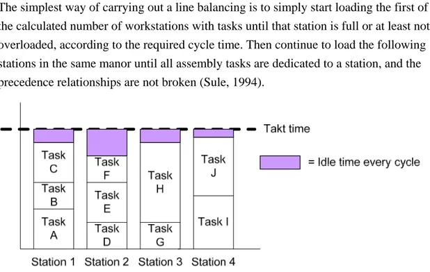
The simplest way of carrying out a line balancing is to simply start loading the first of the calculated number of workstations with tasks until that station is full or at least not overloaded, according to the required cycle time. Then continue to load the following stations in the same manor until all assembly tasks are dedicated to a station, and the precedence relationships are not broken (Sule, 1994).
Figure 2-8. Basic line balancing (Slack & Chambers & Johnston, 2004).
As the figure above shows, the stations are being loaded with tasks without exceeding the desired Takt time, or cycle time. It is recommended not to use the actual Takt time as the loading limit, since that would create disturbances on the assembly line (Ortiz, 2006). Instead, a loading level between 85 percent (Ortiz, 2006) and 90 percent (Hitomi, 1996) is suggested as appropriate.
2.7.3 Line Balancing in the real world
Faulkner (2006) states that in the practical world, the approaches to the line balancing problem differs slightly, from the academic approaches and the complex approaches lobbied by the “expertise” of line balancing. The author states that in his research in the automotive industry that managers are often faced with problems with a gigantic number of solutions, and to find an optimal solution can be seen as impossible. Faulkner (2006) mentions a few aspects that his research has found relevant to consider when a line balancing is to be carried out.
This fact implies that you must consider the fact that a number of operations in a workstation create a identity of that particular workstation. That Identity strongly limits the possible environments the station can be placed at, at the shop floor. Some workstations should not be located next to each other due to environmental aspects
• Unmovable Operations and Zoning Constraints
Some of the operations that are to be balanced simply must be located to certain areas of the factory. This fact delimits the possibility to optimize the balance. Operations that consume a great deal of space can be difficult to assign to a workstation due to limited space of the station.
• Need to Equalize Loads
It is stated that the goal of the line balancing is to minimize the cycle time or the number of workstations. Faulkner (2006) states that the later, is only valid when designing a new assembly line. The goal of minimizing the cycle time is not feasible either since the cycle time is customer and market driven. Instead it is argued that the goal of line balancing should be seen as equalization of the workload.
• Multiple Operator Operations
Faulkner (2006) states that it is beneficial to letting more than one operator work at the machine the entire time. This setting decreases the lead time of that specific task, and also allows the person carrying out the balance to alter the lead time to a desired value. The downside with this setting is that operators in a workstation might have idle time during the cycle, which is inefficiently. It is also very complex planning required in order using this setting. It is stated that making sure that operators are available at the same time can be difficult for larger assembly lines.
2.8 Logistic Aspects of Manufacturing Systems
It was once stated that the flow of materials and efficient logistics are the most difficult aspects to achieve great results within. Unplanned and uncoordinated material positions together with complex material flows can create a great deal of disturbances, quality problems and costs to the company (Lumsden, 2006).2.8.1 Planning logistics
Planning logistics is an essential part of a company’s supply chain strategy, and should thus be in focus when designing the logistics system.
Guedes & Saw & Waller (1995) describes Logistics strategy as designing or redesigning the supply chain in order to meet the demand from customers and the requirements for service as good as possible. In order to be able to do so the logistics strategy must consist of a distribution strategy, manufacturing aspects and a purchase strategy where the purchase strategy gives answers to questions such as which suppliers to use and what would happen if they use this supplier.
The manufacturing aspect deals with sourcing, location of facilities and technology impact. This together with a distribution strategy that describes the policies regarding stock, location of depots, distribution channels and delivery are the strategically issues the company builds its logistics strategy upon Guedes & Saw & Waller (1995).
2.8.2 Long term planning
Long term planning is described as basing the logistics strategy upon the overall business strategy, which describes the path the company needs to take in order to stay competitive and where the company should operate in order to reach its desired customers. Logistics strategy is thus a great part of the overall business strategy because here the company decide how and in which way they are to compete. Aronsson & Ekdahl & Oskarsson (2004) describes two different competitive
strategies that have an impact on the forming of logistics and these are the strategy of cost advantages and the strategy of value advantages.
The cost strategy means that the company focuses upon having a lower cost than its competitors and the value strategy focuses upon giving the customer the sense of a greater value of the product. The optimal solution is of course a low cost to a high value and this is what every company should strive for (Aronsson & Ekdahl & Oskarsson 2004).
Once the company has decided which strategy to compete within the real logistics planning can be started. Aronsson & Ekdahl & Oskarsson (2004) explains the logistic planning as consisting of strategic, tactical and operative planning. Focus is the movement of the product and the activities that needs to be performed and in which order. However, what differs between these planning activities is the time frame. The strategic planning considers planning into the future more than one year away, tactical planning about one to 12 months ahead and the operative on hourly, daily or weekly basis (Aronsson & Ekdahl & Oskarsson 2004).
Figure 2-9. Cost and value strategies (Aronsson & Ekdahl & Oskarsson 2004).
Ballou (1992) describes the design of the logistics channel as an overall question for planning and divides it into four areas
• Delivery service and lead-time decisions - The type of delivery service that is offered by the company affects the placement of the customer order
decoupling point.
• Location decisions - Placement of production and distribution, customers and suppliers according to geography. This decides which customers who get their products from a certain facility and which suppliers should deliver to a certain facility. Decisions are also made for the number of production and distribution facilities to use and their size.
• Warehouse decisions - Where should warehouses be placed and how are they steered. Where do we put safety stock, the size of the safety stock and the steering of material? Here it is also decided how to refill the warehouses with products.
• Transport decision - Which products shall go with which transport? Decisions are made about whether to use boat, air or truck, how large should the
shipments be each time? Also decisions are made about how many products that can be transported together and how to form and plan routes for the transportation in an optimal way (Ballou, 1992).
2.8.3 Planning for inventory
Forming of the warehouse is an important logistical factor. Lumsden (2006) explains that in a warehouse there are lots of different articles existing who has different demands on space , average volume , weight and more and that is why a warehouse is seldom formed from one kind of philosophy or technique. Instead it has the shape of different combinations between shelves, storing and palleting. It is therefore important to form the warehouse so that changes can easily be made when an article changes character. Lumsden (2006) highlights the issues to consider when forming the warehouse and these issues are reproduced below.
• High fill rate - The warehouse should have the highest fill rate possible.
However, it shall not be so high so that the handling of material becomes difficult and so that the transportation increases. The utilization rate of the available volume should also be as high as possible as long as it does not affect the handling as stated above.
• Minimize transportation - In order to minimize transportation and reduce
unnecessary movement of material, working areas should be adapted to the order in which the inventory is moving inside the warehouse. Inventory with high turnover should be placed so that transportation is short while low turnover rated articles are placed further away.
• Make it easy to find and reach - As the headline states articles should be easy
to find and reach without being forced to move other articles or pallets that are in the way.
• Finding the optimal solution - As stated the planning and forming of the
warehouse has a great effect on the material handling and storing of articles. There is a tradeoff between efficiency in storing and the efficiency of handling because as Lumsden (2006) states, effective material handling demands good accessibility of the articles while the storage of the articles needs a high usage of volume. If the inventory turnover increases and there is a more effective way of storing articles the cost of storing decreases. However, this implies that the handling of the material increases since articles are moved and transported more frequently, and thus the cost of the handling increases.
In other words, there has to be a balance between material storage and material handling. Thus, one must consider both maximizing the usage of space as well as being able to easy locate and reach the articles needed (Lumsden, 2006).
Figure 2-10. The cost for storage and handling as a function of the turnover (Lumsden, 2006).
2.8.4 Material Handling
Material handling deals with the way the material is handled from delivery to
production, and how this affects the cost and delivery service (Aronsson & Ekdahl & Oskarsson 2004).
Aronsson & Ekdahl & Oskarsson (2004) describes the activities in material handling as consisting of
• Arrival of goods - Here goods arrive and is reloaded if necessary in order to smoothen the material handling. The goods are registered and enter the company’s system. If there is no time for taking care of these goods directly then a temporary storage location must be available.
• Inspection at arrival - Divided into quality and quantity control. Quality control is the inspection of the goods that they are satisfactory for production.