B.A.D
BLACK.ARMORED.DRONE
Christian Heljeved
MASTERTHESIS 2013
Master in Product Development with a specialization INDUSTRIAL DESIGN
B.A.D
BLACK.ARMORED.DRONE
Christian Heljeved
This degree project is performed at the School of Engineering in Jönköping in the subject field Industrial Design. The project is a result of the master program Industrial Design. The writers are responsible of the result, conclusions and reflections.
Tutor: Thomas Arnell
Extent: 30 points (D-level)
Date: 2013-10-07 Filing number:
Intuitive Aerial AB is developing a new model of their airborne camera rig system to the NAB show (National Association of Broadcasts) in April 6-11 2013 in Las Vegas USA. The airborne Camera rig is an UAV (Unmanned Aerial Vehicle) that targets the professional film and photography industry. Idea generation, sketching, prototype, brainstorming, user research, market analysis, CAD modeling and rendering are some of the industrial design methods used in this project. This project has had a tight time schedule to be ready for the NAB Show. This means that development and production has been hands on.
The result presented in this report is a new design of the Intuitive Aerial airborne camera rig system. That is produced to the NAB show in Las Vegas. After the NAB Show in Las Vegas a concept study of the camera rig system has been made. And is visualised as sketches and 3D model renderings.
Sammanfattning
Syftet med detta projekt var att utveckla en luftburen kamera rigg, den största fokuspunkten i detta projekt har varigt den övre delen av riggen. De stora frågorna har varit att väderskydda elektroniken i kamera riggen, och göra riggen mer portabel för transporter. Jag harandvänt mig av industriell design metodik för att göra detta.
Intuitive Aerial AB utvecklade en ny modell av sin luftburna kamera rigg till NAB Show (National Association of Broadcasters) April 6-11 2013 i Las Vegas USA. Den luftburna kamera riggen är en UAV (Unmanned Aerial Vehicle) som riktar sig mot professionella filmare och fotografer.
Ide generering, skissning, prototyp tillverkning, brainstorming, Användare studier, marknadsanalys, CAD-modellering och data renderingar är delar av det industriella design metoderna som används i detta projekt. Detta projekt har haft en snäv tidsplan för att vara redo i tid för NAB Show. Detta innebär att utveckling och produktion har gått hand i hand. Resultatet som presenteras i denna rapport är en ny utformning av en luftburen kamera rigg som har producerats till NAB show i Las Vegas.
1
Introduction ... 5
1.1 BACKGROUND ... 6 1.2 OBJECTIVES ... 7 1.3 DELIMITATIONS ... 7 1.4 WORDLIST ... 7 1.5 DISPOSITION ... 82
Theoretical Background ... 9
2.1 WHAT IS A UAV CAMERA RIG ... 9
2.2 THE “DOUBLE DIAMOND” DESIGN PROCESS ... 9
2.3 BACKWARD/REVERSE ENGINEERING ... 11
3
Method ... 12
3.1 FUNCTION ANALYSIS ... 12
3.2 DESIGNER´S DRAWING ... 12
3.3 BRAINSTORMING ... 12
3.4 CADMODELING ... 13
3.5 TRIAL AND ERROR ... 13
3.6 QUICK AND DIRTY PROTOTYPING ... 13
3.7 IMAGE BOARD AND MOOD BOARD ... 13
4
Approach and Implementation ... 14
4.1 DISCOVERY ... 14
4.2 MARKET RESEARCH ... 14
4.3 USER RESEARCH... 17
4.4 ANALYSIS OF TODAY’S FLYING CAMERA RIG SYSTEMS ... 18
4.5 CONCLUSIONS OF TODAY’S AIRBORNE CAMERA RIG SYSTEMS ... 20
4.6 DEFINE ... 20
4.6.1 Define target group... 21
4.6.2 Mood board and inspiration board... 21
4.6.3 Brainstorming ... 21
4.6.4 Function analysis ... 22
4.6.5 Evaluating old products ... 22
4.7 DEVELOP... 24
4.7.1 Ideation sketching ... 24
4.7.2 CAD visualising ... 28
4.7.3 CAD batteries ... 28
4.7.4 CAD booms and engine holders ... 30
4.7.5 CAD upper body part... 33
4.7.6 Cad conclusions ... 36
4.7.7 CAD result battery’s ... 36
4.7.8 CAD result booms and engine holder ... 39
4.7.9 CAD result upper body part... 41
4.7.10 Quick size prototyping ... 42
5
Delivery ... 44
5.1.3 Final delivery ... 47
5.1.4 Concept delivery top part ... 52
6
Result ... 57
6.1 OVERVIEW OF THE FINAL PROTOTYPE ... 57
6.1.1 Overview of the concept ... 58
6.2 FEATURES AND PARTS ... 59
6.2.1 Final prototype ... 59
6.2.2 Concept ... 64
6.3 MATERIALS ... 67
6.4 PRODUCTION METHOD ... 68
6.5 COLOUR ... 69
7
Conclusion and discussion ... 71
8
References ... 72
To film a sequence from a top view there are some options. One of the most common is to use a camera beam, another option is to use a steady cam
construction, and the steady cam gives a more dynamic movement than a beam but can’t reach that high. To get a camera shoot from a higher angle a
helicopter is needed. This takes a lot of time and costs a lot of money.
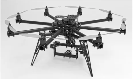
Intuitive Aerial AB UAV camera rig system is developed to make high quality sequence and photos from the air without using helicopters. The big advantage of this camera rig system comparing with the helicopters, is that it is much cheaper, smaller and more flexible.
This project has been about re-design Intuitive Aerial AB UAV camera rig system to the NAB show in Las Vegas 2013. The focus area of the camera rig system has been the upper part of the rig. The big challenge has been to get it ready to the show that takes place on April 6-11 2013.
Figure 1. Intuitive Aerial AB UAV camera rig system. Project benchmark.
This project was completed as a part of a Master thesis in product development and industrial Design at school of engineering Jönköping University, in
1.1 Background
Intuitive Aerial AB is a result of two master theses in 2009.That in September 2010 was made in to a busses. The company is based in Linköping Sweden. My objective with this project was to develop and weatherproof the upper part of the Intuitive Aerial AB´s UAV camera rig system. Using industrial design methods, this report documents the methods used and the development process and the result.
Figure 2. Main parts of Intuitive Aerials UAV camera rig system.
A functional camera rig system shall be presented in the booth of RED digital cameras on the NAB show. The system shall fly and function correctly. The main focus is the upper part of the camera rig system. After the show a concept of the whole rig system with gimbal and landing legs is to be presented to the exhibition on JTH.
Weatherproofing, dismantle for transport and making it as light as possible, has been the three main focus areas in the project. I am using Industrial design methodology.
1.3 Delimitations
Aerodynamic factors are not being presented or discussed in this report only generalizations.
Detailed instruction how to construct the camera rig system are not being presented in this report.
How the electrical components are connected and working are not being described in this report.
Equations and mathematics calculations on strength and solidity not been tested or analysed. Generalization has been made.
1.4 Wordlist
Gimbal= a pivoted support that allows the rotation of an object about a single axis.
CAD= computer-aided design. UAV= unmanned aerial vehicle. ESC= electronic speed controller.
Boom= arm where the ESC and the motors are mounted on.
NAB Show= annual trade show by the National Association of Broadcasters, it takes place in April in Las Vegas Nevada USA.
Coaxial= means that two or more forms share a common axis
RGB= additive color model in which red, green, and blue light are added together in various ways to reproduce a broad array of colors.
LED= a light-emitting diode (LED) is a semiconductor light source RC= radio controlled
1.5 Disposition
Section 2 Theoretical Background Section 3 Approach and implementation Section 4 Result
Section 5 Conclusion and discussion Section 6 References
a UAV camera rig system is a UAV with a camera for movies and photography mounted on it. 1
2.2 The “double diamond” design process
Divided in to four distinct phases, Discover, Define, Develop and Deliver, it maps the divergent and convergent stages of the design process, showing the different models of thinking that designers use.
Figure 1. Design Council UK’s ’double diamond’ design process Discover
The first diamond of the double diamond model starts the project. This begins with an initial idea or inspiration, often sourced from a discovery phase in which the user’s needs are identified:
User research
Design research groups
Market research
Managing information
Define
The second diamond of the double diamond model represents the discovery phase, in which interpretation and alignment of these needs to business objectives is achieved. Key activities during the Define stage are:
Project management
Project sign off
Project development Design
The third quarter of the diamond marks a period of development where design-led solutions are developed, identified and tested within the company. Key activities and objectives during the Develop stage are:
Testing Visual management Multi-disciplinary working Development methods Testing Delivery
The final quarter of the double diamond model represents the delivery stage where the resulting product or service is finalised and launched in the relevant market. The key activities and objectives during this stage are:
Final testing
Approval and launch
Target evaluation
systematic analysis to understand how the product is designed and then after creating it. This is of course this is a delicate balancing act with patents. Reverse engineering has a big market in the aftermarket for automotive parts. Sadly many use reverse engineering to make illegal pirate parts.3
3 Method
3.1 Function analysis
The function analysis is an abstract way of analyzing and developing functions of a product. The method is a way of helping the development of a product without thinking of shapes, dimensions and materials. The function analysis is supposed to describe the product´s functions and parts, and forces the user to think in an abstract way, preventing the user from jumping to solutions immediately. Function analysis helps to find different kinds of solutions to the same problem.4
3.2 Designer´s drawing
“A designer´s drawing has three main functions:
It is a mean of externalizing and analysing thoughts and simplifying multi-facet problems to make them more understandable.”
It is also a medium of persuasion that sells ideas to clients, and reassures them that their design brief is being satisfied.
It is a method of communicating complete and unambiguous information to those responsible for the products manufacture, assembly and
marketing.”
According to Piper” pipes a designer need to be a paragon, proficient in a whole range of apparently disparate drawing skills. At the concept stage as well as being able to clarify on paper his or her own thoughts, it is crucial to be able explain in a few economically placed lines, perhaps at a briefing meeting with a client, exactly how the as yet on –existent product will look, feel and fit together, demonstrating that all the various specification imposed in the design by the client´s brief will be resolved within budget”5
3.3 Brainstorming
Brainstorming was invented by a man named Osborn as early as the 1930s. Apart from producing large numbers of ideas, brainstorming is based on another very important principle, the avoidance of premature criticism. Of course ideas must be assessed critically, but an all too critical attitude often holds back the process of generating ideas.6
you is the possibility to render the CAD model with material and colours. This makes it easy to visualise what the finished product is going to look like.7
3.5 Trial and error
The purpose of the trial and error method is not to find a way problems is solved. The trial and error method is good for problems where there are multiple chances of a correct solution, and it is not such a good method for problems that doesn’t have multiplied solutions.8
3.6 Quick and dirty prototyping
Using Plasticine clay and modeling foam, quick form and size models, was created for evaluation. It leads to a discussion about sizes and shapes that resulted in decisions.9
3.7 Image board and mood board
Image boards and mood boards originates from marketing and consumer research. Image and mood boards is a collage that shows the intended user and his/her lifestyle.10
7 Dick Powell, presentation techniques, Computer aided design- CAD p.46-50 viewed 5 may 2013 8 Exforsys inc, the uses of trial and error to solve problems, viewed 23 September 2013,
http://www.exforsys.com/career-center/problem-solving/the-use-of-trial-and-error-to-solve-problems.html
9 Bjarki Hallgrimasson, Prototyping and model making for product design, Types of clay, Plasticine clay. P138-139 viewed 23 September 2013
4 Approach and Implementation
The process of developing a new design of Intuitive Aerial AB airborne camera rig system, has not been a linear process or method. Because of the tight
timeframe a few of the steps in the design process and methods have been dropped and/ or hastened. Other parts has been made simultaneously with each other to save time.
"If you can't convince them, confuse them." (Harry S. Truman)
Reflecting over the process and methods now, I can see that some parts of the UK´s double Diamond Design Process model has been used. The main method that has been driving this project forward has been reverse engineering.
Reverse engineering is the process of extracting the knowledge or design blue-prints from anything man-made. It means that it has not been any guarantees that the parts and design would work until it has been produced and tested. Trial and error has been used. Without time for errors. The reverse engineering has been implemented in the Double Diamond Design process model.11
The structure of the Double Diamond Design process has been used to organise this report of my design process.
4.1 Discovery
Gathering information and obtaining knowledge from a variety of sources, that can be of value to the project was made in the discovery phase. However, it has been an ongoing process through the whole project. The discovery phase did not occur in a disciplined order. It has provoked ideas and questions. The discovery phase has given me a deeper meaning and understanding in the field of UAV camera rig systems.
The discovery phase was a necessary step to get in to the world of UAV and RC flight. It gave me an understanding and an insight in people how builds and uses UAV camera rigs systems. The discovery phase did also reveal a deeper understanding of what the people that has insight in this market values and thinks is important.
4.2 Market research
The starting point of the project was to examine the market of the airborne camera rig systems. Who are the competitors and what other solutions are there on the market? To my help I had material that John Lindén had collected
during a customer survey that was made for the Intuitive Aerial AB see attachment 2.
Figure 4.
As showed in figure 4 there are some different solution on the market today. The solutions showed in figure 4 are those mainly used in the movie and photo industry today.
Figure 5. Camera beam mounted on rails for movement. Figure 6. Operator with a steady cam solution
Figure 7. Helicopter with a gimbal mounted underneath and in the front. Figure 8. RC helicopter with a gimbal build on it
Showing in figure 5 the camera is mounted on a beam that is mounted onto rails, to give the beam movement back and forward. Otherwise the beam just gets the moves up and down. The problem with this solution is that it gives a static movement and is restricted.
In figure 6 there is a solution where they have mounted the camera rig on to the camera man. It gives a lot of movements and freedom, the setback is that it requires a skilled operator to get good footage. And the angle of footage are restricted to the camera man.
Figure 7 is a footage of a helicopter with a gimbal camera rig system mounted in the front. This gives a lot of freedom and the ability to get good footages from high angles and altitudes. This is the best solution to getting the best images from the air. The setbacks with using helicopters is that it is expensive and due to regulations they can’t fly in the cities.
Showing in figure 8 is a RC helicopter that has been modified with a gimbal construction. This is a good solution to get footages from high angles to a low cost/good price. The biggest concern of this solution is that it requires a skilled operator and the process of learning to fly is hard and long.
Figure 5, 6, 7 and 8 are showing solutions for the high end industries that are used today. Figures 9 and 10 are showing two multirotor camera rig systems that claims to be for the professional market.
Figure 9. Quadrocopters camera rig system CineStar 8 for the professional market.
Quadrocopter Cinestar8 showing in figure 9 is a Multi-Rotor system for the professional film and photo market. The CineStar 8 has 8 arms and the
dimension of 1000x900x350mm and has the gross vehicle mass of 6200g. The Cinestar8 is available as a ready to fly system or you can buy it in parts for assembly. Cinestar8 is made mainly from carbon fibre. And/it costs around 8 000 dollars for the ready to fly version.
Figure 10. Microcopters camera rig system for the professional market MK AEF Okto XL.
showed in the figure 10 is Microcopters airborne camera rig system MK AEF okto XL. It targets the professional market. The system has 8 arms and 8 engines as the Cinestar8 has, and can be purchase as a ready to fly or “build it yourself kit”. The ready to fly kit cost around 7.300 dollars.
4.3 User research
In the customer survey which Johan Lindén made for Intuitive Arial AB in 2011 see the attachment 3 Johan Lindén has interviewed producers, sound technicians, photographers and moviemakers. This has been helpful to understand how the product can be used by the different groups, and their different needs.
4.4 Analysis of today’s flying camera rig systems
In the high end photo and movie industries the most common solution to get the footage that is acquired from the air, the helicopter is the best solution for capturing the footage. Figure 11 is showing a typical solution on how a camera rig system looks and is mounted on a helicopter. The camera is mounted on a gimbal that is welded to beams that is attached on the helicopter. The system works by a pilot controlling the helicopter, a camera man controlling the camera, and a director controlling them.The gimbal construction for the helicopter is not something that is mass-produced. It is designed and modified to fit the needs of the user. Therefore, they vary a lot in shapes and size.
Figure 11. Showing a gimbal construction mounted on a helicopter.
The unmanned camera rig systems, UAV´s or drones as they also are called, are modified radio control helicopters, or RC helicopters that have been
modified with a gimbal solution. There is one pilot that operates the helicopter from the ground and one camera man that operates the gimbal with the camera also from the ground. Figure 12 is showing a typical RC helicopter. The typical RC helicopter is built for performance and fun and looks engineered. It has a lot of showing parts and a lot of moving parts. In figure 13 there is a RC
helicopter that has been modified with a gimbal system to take pictures as flies. As showed in figure 13 it looks very engineered and self-built. A lot of
showing cables and moving parts, and it makes it look very complex and fragile. Little attempts have been made to give the RC camera rig a finished look. This is what RC camera rig system generally looks like.
Multi-Rotor system isn’t important at all, it is the functionality that is priority.
Figure 14. Quadrocopter Multi-Rotor system Cinestar8 one of the main competitors of Intuitive Aerial.
Figure 15. Mikrocopters Multi-Rotor system MK AEF Okto XL main competitor to Intuitive Aerial.
The mechanics in a Multi-Rotor system is much less complex than in a RC helicopter system. This means that the design isn’t controlled by the mechanics of the system and are much free. This is showed in the design of the system that can be found on the market today. When it comes to the UAV camera rig
systems, functionality are often the main goal. And it shows in the design of the systems. Less moving parts means less maintenance and lower costs. The reason why the Multi- Rotor system suits movie and photo making so good, is because, they can be built cheap and they are low in maintenance. Parts can quickly be switched out and they are not that complex, has great stability and control in the air.
If you compare the RC helicopters to the Multi-Rotor in general the RC
helicopters are a lot more defined than the Multi-Rotors. The Multi-Rotors are often just motors and circuit boards mounted on a frame. The frame can be made from aluminium, plastic, carbon fiber or wood. The RC helicopters are much more advanced due to the moving mechanics in it and therefore they are more expensive.
Figure 16. RC helicopters
4.5 Conclusions of today’s airborne camera rig systems
The multi rotor systems were born from the RC helicopter system. It is adevelopment that has occurred to make the RC helicopter flying easier and cheaper. With less moving parts and a simple construction, Multi- Rotor system has made it cheaper and easier to fly RC/drone crafts. The Multi-Rotor system is made for fun flying. The electronics and not the aesthetic has had the
development priorities during the years. The Multi-Rotors system is a relative new way of flying. And the focus has been on developing the system to fly as good as possible and how it looks doing it.
The electronics of the Multi-Rotor system are now very good and advanced so development of the aesthetic and other functions can begin to be considered. This is what is happening in the market at this point. Performance and stability has been the focus point so far and that is up to the electronics. When
development has come so far so it meets industry demands, development of the rest of the systems can begin. This is where the Multi-Rotor industry is today. The companies that are beginning to implement design properties and thinking of development of the rest in the Multi-Rotor systems are those who can get a big advantage in the market.
It is an opportunity to create the market standard of what the Multi-Rotor camera rig system is supposed to look like and how it is supposed to work. What it essential is that the company’s has the opportunity to make their design the starting point of the whole flying camera rig system´s future industry.
4.6 Define
About 1/3 into the discovery phase a narrowing down was made and some guideline for the project was created. The project hasn’t had a defined design
4.6.1 Define target group
Intuitive Aerial vision is made for bringing the cameras to the sky for the high end movie and photo industries.
The target group of Intuitive Aerial camera rig system is the high end movie and photo industries. In the industries there are different target groups such as the production companies that are the purchaser of the equipment’s, then we have the users of the equipment such as cameraman and pilots.
4.6.2 Mood board and inspiration board
Mood boards and inspiration boards was created to help find inspiration, and to see if the company and I had the same vision for the project. The mood board helps to get a discussion started on in what kind of style direction to aim for. The mood board consist of a lot of images which are used to set a
feeling/mood. See attachment 4 for mood board and inspiration board.
4.6.3 Brainstorming
A brainstorming session did take place at the intuitive aerial office in
Linköping. The brainstorming session was made together with engineers from Intuitive Aerial. It was documented on a whiteboard. The brainstorming session helped to bring out some problem formulating and some interesting ideas to build on.
Figure 17. Showing parts of the brainstorming sessions on Intuitive aerial
4.6.4 Function analysis
The function analysis of the product is done to understand which functions are necessary and to ensure things aren’t forgotten. The function analysis of the project has been an open document and changes has been made frequently as the brief changed see attachment 1 for the function analysis.
4.6.5 Evaluating old products
Before creating a new design to the existing camera rig system an inspection of the old model was made. Some problem areas which needed improvement were found, the top part of the camera rig system. The areas of the motor and ESC holders are marked with purple in figure 1.4, batteries marked with yellow in fig 1.4 and the middle part marked white a green colour in figure 1.4.
Figure 18. Is showing the top part of the UAV camera rig system
On the end part of the boom the ESC and engine are mounted as showed in figure 18. The ESC are mounted close to the engine to gain the cooling effect from the spinning propellers. The exposed ESC and cables gives the impression
Figure 19. The ESC and motor carrier on the end part of the boom
Figure 20. ESC and motor part on the end part of the boom showed from the top.
The top, middle part and battery holder are showing in figure 21 below. The big yellow battery and its cables gives the impression of being messy and complicated. Showing of the cables has the effect of a look of a work in
progress stage and not a finished product ready to use. The exposed cables and connections area is a safety risk for the system, because they are in much greater danger of being damaged either by the elements or during transport and handling.
The main conclusion of the top part of the UAV camera rig system is that the exposed circuit board and the cables showing gives the impression of being a work in progress. The openness of the design is also a safety risk. When no protection of important components and parts is made, they are in greater risk of being damaged.
4.7 Develop
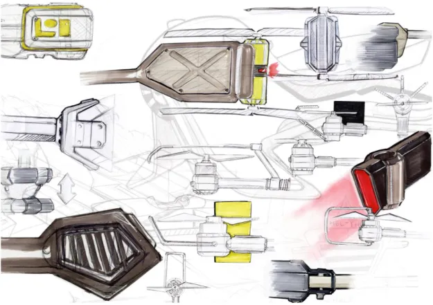
4.7.1 Ideation sketching
Ideation sketching was used to visualise ideas and concepts, to explore the possibilities and constraints. The ideation sketching help to get a better grip and understanding of the limitations of the project. The ideas sketches has been documented on paper, and good and bad idea´s has been discussed and
evaluated by the company. The ideation sketching process has not been a linear process. A lot of “jumping” has occurred in the process: Back and forth from sketching to CAD. The ideation sketches has been a very good discussion means between me and the company.
The starting point of the design sketching phase was the batteries. I/we wanted to explore a better solution than the existing one to mount and use the batteries. The company had plans of creating their own battery system for the UAV camera rig systems. Another reason for having batteries as a starting point is that they take up mostly of the space in the top of the main upper body. It also felt like a natural way of starting: from the top and then work our way down.
Figure 22. Showing sketches of different battery packs.
The three main ideas of battery packs was explored. The first was a round “plutonium rod” battery pack. The second battery pack was one with a twisting lock mechanism and the third a more conventional battery back (only more rugged). Many different ideas and concepts were generated in the sketching phase, some of the ideas are showed in figure 22.
Figure 23. Showing different sketches of engines and ESC holders.
The next phase in the ideation sketching process was to design and develop the engine holders. The goal was to enclose the control card circuit board (ESC) for the engines. The control card circuit board produces a lot of heat: having them under the propellers is a good idea for the cooling effect. The idea was to enclose circuit cards near the propellers and have cooling fins attached to the circuit board (as you can find on computers). So the propellers cool the cooling fins that are connected to the circuit card and in its turn cooling it. Some of the sketches are made for coaxial mounting of the engines and some for single mounting of the engines. This is because I had to plan for both solutions.
Figure 24. Showing sketches of different shapes of middle top part.
Parallel with the battery and the sketching of the engine holder, a concept was created of the top part of the UAV. In this part of the ideation sketching the thumbnail technique was used to get a well spread of ideas down on paper as fast and easy as possible.
The main body shape is controlled of the 8 arms that was going to be mounted on it. The essential idea was to have some direction of the body and to make it as small as possible for good weight and aerodynamic properties.
The sketches and ideas were evaluated by me and the company, some were picked out as good and others as bad ideas. Some of the good ideas are showed in figure 24. An evaluation was made and some ideas were chosen to work further with in to the CAD process. The step from sketches to CAD modelling was very close to each other. Shapes and forms was not as thoroughly explored as they could have been. A lot of exploring was made in the CAD modeling stage.
4.7.2 CAD visualising
After sketching and idea generating a CAD modeling process was initiated. The CAD modeling process was almost parallel with the sketch process, just one step ahead. A lot of ideas generating has been done in the CAD modeling stage, to speed things up for producing an underlay for production as fast as possible. Alias has been used to model underlays for production. Inventor was used to make the CAD models for production. Alias has been used to create models for rendering and concepts.
4.7.3 CAD batteries
The requirement on the battery design was that it should have some indicator of power, be easy to connect, portable, take up as little space as possible and to tolerate rough handling. The Intuitive Aerial origin thought with the batteries was to build a housing for the betters they are using today.
For bigger pictures of the batteries and engine holder see attachment 5.
Figure 25. CAD sketch of battery pack
The first type of battery design is a rugged battery housing with 2 handles that can slide up and down. This is also the locking mechanism when mounted on the UAV. On the top of the batteries there is an indicator of the power left in the battery cells.
A main switch for on and off is located on the top of the battery. The switch is a simple toggle switch with a red cover. The switch was made as a toggle switch with a read cover because I wanted to give it an army rugged feel and look. The battery housing is supposed to be made from carbon fiber plates screwed together with Torx screws indicated with orange in figure 23. On the ages the housing a rubber surface has been mounted for protection.
Figure 26. CAD sketch of JEEP battery pack style
The second type of battery pack design is a more “clean design” made from carbon fiber plates, which uses screws to hold it together. The battery pack has 2 handles on top for carrying, a power indicator and a main switch. I got the inspiration for this design from an army jeep reserve gas tanks. The thought is that the battery power connection is underneath or on the side so you slide or lift it in position to connect it to the main body. And the locking mechanism is situated on the main body.
Figure 27. Showing CAD sketch of rod power cell battery pack.
The third and final concept of the battery pack is the round plutonium rod style battery pack. The power connections is located underneath, as showed in the circle in figure 28.The battery pack has a fold up handle on the top surface. In figure 28 the handle is folded up on 2 of the packs and down on 2 of the other. The black parts on the pack is a rubber surface for rugged handling. And to get a friction surface for a better grip.
Figure 28. CAD sketch of rod power cell battery pack. With handle up and down
The main body is made by sheet metal and is screwed together with orange anodized aluminium Torx screws. The power indicator is the green light on the side and the bottom of the battery pack. The light is a LED light that fades when the power in the battery is used.
4.7.4 CAD booms and engine holders
The starting point with the engine and ESC holders is to build in the ESC´s in a protecting housing near the engine and to have cooling fins on the ESC´s. The idea was to produce them as they was built from the star only do it better, but use the same principles. Building them from different parts. The main goal with the ESC and engine holders is to make it as light as possible and as durable as possible. If the UAV bumps in to something it is the propellers and the engine holders that takes the first hit. All the concepts of the booms and engine holders has in common that wiring is done on the inside of the rods that connects the engine and ESC holder with the body part of the UAV.
The endeavour has been to make an engine and ESC holder as light and thin as possible. The goal was to try to reduce some turbulence and the negative air current that is generated from the propellers.
Lights has been mounted on all of the design suggestions for the ESC and engine holders. This is a LED strip to indicate where the UAV is in the air. Right side of the UAV has green light and Left side has red light. This is mean to make it easier for the pilot to navigate and control the UAV system.
The shafts/rod that connects the body with the engines and ESC holders are made from either carbon fiber rods/hexagonal rods or titanium hexa-rods. For bigger pictures of the ESC and engine holder see attachment 5.
Figure 29.
One of the first ideas for the engines and ESC holder was to build in the motor to protect it. This engine and ESC holder do that half way. It’s protected but you can see the motors spin. This ESC and engine holder is made from plastic and aluminium and carbon fiber, The ESC is mounted behind the carbon fiber plates that is showed with a red circle in figure 29 the plate is mounted with screws. The cooling fins on top of the engine and ESC holder showed in Figure 29 with a green circle, are made from aluminium and is anodized blue.
Figure 30.
In the design of the ESC and engine holder shown in figure 30 the idea is that the engine is mounted in a frame built from aluminium, there is a carbon fiber plate that encloses the aluminium frame. The frame is hollow behind the plates to save weight. The carbon fiber plate/lid is screwed from the side. In the aluminium frame work behind the carbon fiber plate is where the ESC´s are mounted for protection. On the outside top and bottom part of the frame, some fins has been milled out from the aluminium to act as a cooling device for the ESC´s. On the front part of the Engine and ESC holder some RGB LED are being mounted.
Figure 31. Concept with logos as position lights
In figure 31, you can see a simplified and small ESC/engine holder. The principle is essentially the same as in figure 30 and 29. An aluminium frame is casted or milled out. A carbon fiber sheet is swept around the aluminium frame. The frame and aluminium is swept to fit the radius of the engine. The position LED lights is made as Intuitive aerial logos on the sides in this model. The cooling fins showed in the black circle in figure 31 are attached to the circuit board and cools it. The fins are mounted in an acrylic glass block that has been milled in to fit the engine and ESC´s. It is lit by an RGB LED light that gives it a glow that spreads showed in the red circle in figurate 31.
Figure 32. Concept based on concept in figure 31
Figure 32 is showing a concept based on figure 31. The difference is that it is bigger, has more space for the cooling fins and has a direction. The sliced angle in the beginning of the engine and ESC holder was made for making it look less heavy and to give it a forward motion look when standing still on the ground. The concept shown in the pictures 31 and 32 are concepts of an engine/ ESC holder with a single engine.
The company hadn’t decided if the engines and ESC holder should belined up or not at this moment in the process. So different concepts was made. The underlying concept is that this part of the UAV is supposed to look very heavy duty and ruff. A lot of army products has been an inspiration source.
UAV.
The CAD stage of the upper body part has been made for getting ideas and a discussion platform. Proposals of different designs to the body has been made with different accomplishments.
Figure 33. Showing CAD sketches of top part.
In figure 34, one of the first CAD design sketches are showed. Focus had been on connections with the main body and the boom arms. I put focus on the connections because it is an integration point and one of the weaknesses of the construction. To make the construction light and durable, the taught was to have a platform with a hole in the middle where the circuit board is mounted and where the cables to the boom-arms can be found.
The part showing in figure 34 is there to replace the green coloured part in figure 3. The green circle in figure 34 is shows a reinforced interaction point made from molded plastic. For different views of part look in attachment 6. In the middle in figure 33 a wire-damper with springs is showed, this is a solution that is taken from the existing solution. In picture 33 they are made more robust for a solid look and has been coloured orange to indicate
movement. Under the dampers there is supposed to be a connection point to the gimbal.
Figure 34. Showing concept on a body
In figure 34 there is a further development on the concept. Showed in figure 33. In figure 34 the model has the same boom holder parts. The concept has a top with a handle in the back for carrying and the batteries are mounted inside of the body.
The UAV concept has 4 aluminium attachment points on the top. The
attachment points are there to have anchor points to a bench rig for testing, and to mount extra parts that can occur in the future.
The body has a drop shape for the aerodynamic features and to give the body a clear direction.
Figure 35. Concept on a rack and battery access.
To be able to have easy access to the battery for change and carrying. The idea is that a front piece of the body is removed and the battery pack from figure 26 slide in. The front piece is the attached before flight.
A rack has been mounted in the attachment points showed in figure 35. The rack is thought to work as a mobile platform where things can be added if necessary. The rack can be folded up for better access to the battery pack.
Figure 36. Refined concept, inspired by previous figure. And colour proposal.
Figure 36 there is a more refine concept showing, this concept is a combination of figure 34 and figure 35 the boom-arm and engines holders are the ones from figure 32. The battery is accessed by folding up the rack and the lift the battery out.
The green colour on the body is a monster green colour the same that the energy drink company has in their logo. The colour was chosen to be monster green because it sticks out and can be associated with the energy drink
company that has association to extreme sports.
Showed in figure 36 the monster green colour is added to an insertion in the body part. This is insertions is there for to give the body aggressive look and to reduce the area. The insertion is also an air ventilation.
Figure 38. Showing sketches of different battery packs
In figure 37 and figure 38 a concept is showed on organic shaped construction to the camera rig system. The concept I built around an 8 arm construction and a battery pack in the middle of it for a center of gravity purpose
4.7.6 Cad conclusions
My CAD process could have been a lot smoother and faster if the project goals had been more defined before starting the process of CAD modeling. Essential parts that was undefined before starting the CAD process was, how many boom arms were needed and how to construction them. It takes a lot of time and effort to start a CAD modeling process without a clear goal. Inventing shapes in a CAD takes time.
The process becomes confusing because the point of departure was changed several times. It means that the process needs to start over. And that took a lot of effort and mental power.
The process becomes confusing when the point of departure is changed several times. It means that the process needs to start over. And it takes effort and metal power.
4.7.7 CAD result battery’s
The end result of the CAD batteries is showing in figure 39 it was determined that due to time shortage Intuitive Aerial didn’t have time to produce their own battery casing. Intuitive Aerial decided to use the existing solution of battery mounting showed in figure 21 the solution builds on that the batteries is strapped on a carbon fiber plate that is screwed in to the body, the batteries is strapped on to the carbon fiber plate with Velcro straps. The battery plate was made to fit the design of the upper part with six little extruding arms from a round shape showed in figure 39.
The solution is easy and functional. And not in terms what I think a UAV camera rig system for the professional market should use to attach it only energy source with. The battery’s is a big part of the UAV camera rig system and takes up mostly of the top part. It is an interaction point and one of the first thing you see on the UAV.
Shown in figure 40 is my solution to a battery mounting system it builds on the concept from figure 35 with a bracket solution in aluminium mounted on the ridge of the boom arms attachment points.
Figure 40. Bracket and battery roof top box.
The intention whit the bracket is to give the UAV a more robust and light appearance. The bracket also gives the UAV a clearer direction of back and forward.
Showed in figure 40 and 41 a battery roof box was created as housing for the batteries. The idea is to attach the roof box on the bracket. This is an easy solution of hiding the battery in a good way that highlights the appearance of the UAV, Give a clear forward direction and better aerodynamic properties. The roof box has room for three batteries.
Figure 41. Battery roof box, Aerodynamic housing for 3 batteries.
The Green line showed in figure 42 is where the box opens, the green line is there to indicate a function and interaction. In the back there is a screwed green power cord. Instead of trying to hide the power cord it is highlighted and integrated to the design. The box is made of carbon fiber to match the rest of the UAV.
Figure 43 Showing comparison of bracket and plate solution on battery mounting
4.7.8 CAD result booms and engine holder
Showed in figure 44 is a unibody boom arm that is the final design to the
engine and the ESC holder. It was decided to make the boom arms as a unibody and have the inside hollow. Showed in the green circle in figure 44 is an
aluminium plate where the ESC are mounted on the back of the aluminium plate that works as a cooling device for the ESC. The aluminium plate is then screwed to the unibody.
The engine mounting showing the red ring the figure consists of two
aluminium parts, the first part is a round aluminium plate that is attached with screws underneath to the engine, and the second part is an aluminium ring that the first aluminium part fits in to. The aluminium ring is epoxy glued to the unibody boom arm. The aluminium plate is mounted with screws from the side of the aluminium ring.
Showing in the blue ring in figure 44 is the female electronic connector made from plastic. On the main body the male connector is mounted. Connected it brings power to the ESC´s and engines through cables in the unibody arm.
Figure 44 showing an exploded view of the final boom and engine bracket
Figure 45. Showing boom arm assembled
Figure 45 is showing the boom arm assembled, in the orange circle of figure 45 is a hexagonally shaped rod that is connected to the air coil- shaped part.
(Behind the engines indicated with a purple circle in figure 45). The rod is hexagonal therefore making mounting easier. It becomes clear if the mounting of the arms to the main body is incorrect with the hexagonal shape, because the arm will be in an unnatural angle.
4.7.9 CAD result upper body part
The result of this CAD stage ended with a body that is thin and small. The body was made to fit the inside components as tight as it can. The body that was produced is an extremely functional design of the body.
The body is as thin and small as the inside components allowed it to be. And the effect of this is a light design and the thinness of the body makes it less possible to be affected by the wind when flying.
The arm mounts was made in a hexagonal shape for two reasons: first it was determined that the UAV is going to have 6 arm, then the 6 arms has the jointly with the hexagonal shapes. Second is to have the help of the hexagonal shape when mounting the boom arms.
Figure 46 CAD result of the main body.
The ribs on the body out on the boom mounts was made for taking the force of the arms in an up going direction. Showing in figure 46 with pink circles is an attempt of giving the main body a front.
The top surface is offset down so walls are created around the body the wall connects with the ribs going out onto the boom mounts. This was made to achieve a stiff construction. In the pink circles there is an opening in the wall and the offset is sloped down as a hill. This is made to give the UAV a front. The two ribs that is linear with each other marked with a green line on figure 46. Those ribs are made a little bit smaller than the other four. The reason is that it enhances a forward direction.
4.7.10 Quick size prototyping
Because it is hard to get a feeling of size and volume from a CAD model, a quick mock up model was milled out in foam. This was proved to be very helpful when of deciding a size. After scaling up the size of the main body a second size mock up model was milled out and a decision was taken to scale down the size of the model a little bit.
Figure 47 first size prototype milled out in Sicla foam.
5 Delivery
5.1 CAD
The CAD models that came out from the CAD steep has been used to make moulds. The moulds were then used to produce the different parts of the camera rig system.
5.1.1 Boom arms
Showing in figure 48 is the final CAD model of the boom arms. Showing in figure 49 is the result of the CAD model boom arm. Produced in carbon fiber and assembled with the engine.
Figure 43. CAD model of the top. Where the booms are connected to the electronics.
The top part is constructed in two main pieces that are clamped together with screws at the moment. The further development of this would be to make the opening and closing of the top and bottom part faster. It is the clamping of the screws that holds the boom arms in place. So it needs a reliable way of
clamping the parts together. The patterns on the ribs was made for reducing material and to indicate screws positions. And to give the part some bad and dangerous looking shapes.
Figure 45. Showing all of the parts of the UAV´s top part.
The UAV is constructed in the way that the bottom part of the UAV where the gimbal is attached. Bottom part of the main shell is. The next layer is some reinforcement material for the booms. Then we have the middle there the boom arms are, in level with it there is an electronic plate where the cables and circuit boards are connected. The next layer is the upper half of the reinforcement material to the boom arms. Then the upper body half and on that is the battery plate screwed on. Everything is clamped together with press nuts.
Showing in figure 53,54,55,56,57 is CAD renderings of the finished UAV camera rig system. In figure 58, 59, 60 there are pictures of the final delivery to the NAB Show in Las Vegas.
Figure 47. Overview of the camera rig system. With landing legs camera and gimbal.
Figure 48. Side view of the camera rig system. Whit the gimbal and landing leg mounted.
Figure 49. Showing a top view of the camera system with the gimbal mounted under the top part.
Figure 50. Showing the top part of the system with the battery plate and the Intuitive Arial logo milled in the carbon fiber.
Figure 51. Assembled at the NAB show in Las Vegas with a RED EPIC camera mounted on the system.
Figure 53. Finished UAV camera rig system delivered to the NAB show.
The final product was named BAD and stands for Black Armored Drone And can be purchased on the internet, on the web page
The final delivery was made to the NAB show in Las Vegas 2013.04.06 and was flown and put on display in the RED camera booth at the fair. For the flight movie from the show visit.
http://www.youtube.com/watch?v=XQdM0IgzwCc
5.1.4 Concept delivery top part
The concept UAV was made after the NAB Show delivery. This stage of the process was made because some stage of the NAB drone was rushed. The position lights was one function that wasn’t developed to the NAV drone. I wanted to give the boom arms position lights and to amplify the shapes of the overall top part. The concept had the intention of being something that would fly 5-8 years in the future. But it turned in to a development stage of the UAV NAB drone. Because to the rushed process of it.
Figure 55. Concept design of the top part
The shape of the carbon fiber pocket for the sec has been extended out round the engine and continues out to end in an angle. The angle was made to give the UAV camera rig system a more aggressive look. The angles have the function of directing the lights down.
Figure 57. Showing a top overview.
The middle part of UAV drone has left the same as the NAB UAV. So that development of the other part could be made instead.
Figure 58.the Back part of the UAV concept.
The handle that was supposed to be made for the NAB drone is a part that the timeframe didn’t allow to be made. That is a reason why the concept stage was made in to development of the UAV NAB drone, it was that it had too many loose ends. The handle is located in front and back of the UAV. The handle is made so there is a clear way of carrying the UAV. And not use the boom arms to carry it in. The handle is connected to the UAV´s bottom part with
aluminium mounts. The same way the bracket on the top part is attached.
Figure 59. Concept of the top, gimbal and landing legs
The landing gear consists of 7 main pieces of carbon fiber, one leg is made of two pieces of carbon fiber parts to build on leg. The two carbon fiber parts is connected through 4 aluminium bars and one shock-absorber. Seen in figure 67.
Showing in figure 66 there are lights added to the gimbal. This was done to give the cameraman better overview, in which direction the camera and gimbal is pointing. The light has to be a frosted or a soft not to interfering with the filming.
Figure 60. Concept landing gear shocks and connections.
The split legs was made to have the alternative to dismantle the landing gear for easy packaging. And to make it easier to replace if damaged in a hard landing. And the shock-absorber solution is made with the intention to prevent the legs of breaking during a hard landing. And to have stability if landing on
Figure 61. Back view of the landing gear
The landing gear is a tripod construction that often is used in camera stands. The tripod construction is well known for its properties of supporting the weight and maintaining the stability of objects. The solution works well as the camera is mounted inside of the tripod landing gear. With one leg directly behind the camera, there is a 120 degree angle between the front legs, the 120 degrees is to maintain stability and to get a good camera shoot without filming the legs.
Figure 62. Side view of the landing gear
The back landing leg and the gimbal has not been made in to one piece because if there is a heavy landing the leg should break and not the leg and gimbal. The camera rig can be operated without legs in an emergency situation. But
aren’t connected. This is concept was taken from the existing flying camera rig system Intuitive Aerial is manufacturing.
Figure 63.perspective view of gimbal and landing gear
In the yellow circle in figure 70 the upper part of the outer landing leg is marked. As showed in the figure the leg is wider on top and the gets narrow as going down. The landing leg is made wider on the top to handle the forces in the joints when landing. The bigger top part of the landing legs has an aesthetic value to it. It makes the landing gear look more robust and not so fragile. And it gives the camera rig a more of a movement in an upwards going direction. The joints and the dampening was made visible in this concept, because I wanted to create a more robust feeling to the camera rig. The Hulk green colour was put aluminium parts to indicate screws and mounts. And to be associated with a strong and abrasive, the carbon fiber has been left untreated to point out that most of the camera rig system is made of a light and durable material.
been achieved, because in the RED (red digital cinema Camera Company) exhibition stand at the NAB show 2013 there was a flying camera rig system from Intuitive Aerial flying and functioning properly.
The final product is showed in Figure 71. The final product has succeeded to express quality and a robust filling.
6.1.1 Overview of the concept
The final concept was made to be label to experiment with the shapes and forms and to break the guidelines that was made for the final product showed in Figure 71. The concept is an experiment in what the final product could have looked like if factors like cost, time wasn’t an issue.
The concept study of this project was made after the final product was finished. The final product was finished 2 months before the final end time for the
master this work end date. There for the final product is the underline for the concept study.
The final concept 3D model is showed in Figure 72. Concept 3D model was made as a further development of the final product showed in Figure 71. The biggest differences between them is the landing gear. The landing legs on the final concept was already developed and wasn’t modified to the NAB Show. The landing legs on the concept has a joint for suspension, and for travelling. The second biggest change between the final product and the concept is that the concept rig has the position lights on the gimbal and are more integrated to the rig for a more defined look.
storing, the break points of the parts are showing in figure 76. Landing legs, gimbal, top cover and the boom arms are the main building frame for the camera rig system. All of this carbon fiber parts are hollow to save weight and to case the electronic parts and wires for protection. The boom arms has a hexagonal shape that’s is in align with the hexagonal cavities on the top casing. At the ends of the boom arms there are contact pins that are inserted to female pins in the top casing. It is between this contact surfaces the power and
electronic signals are being transferred to the propeller engines and the electronic speed controllers. In figure 74 the pins and the connection are in showed.
Figure 66. Overview image of the final camera rig system
Figure 67. Connections from the top casing and the boom arms
Figure 68. The 4 main carbon fibre parts of the camera rig
Figure 69. The splitting points of the main carbon fibre parts.
On the top casing there is a plate showing in figure 77. On this plate the batteries are mounted, the plate holds 3 batteries and are attached with Velcro straps showing in figure 78. The batteries are placed on the top and in the centre of the camera system to give it stability and control when flying. The batteries was placed on top and attached with Velcro straps to be easy to access and to change. Another reason for the localisation of the batteries is that if needed more than 3 battery there is a possibility to stack them upwards.
Figure 71. 3 Batteries attached to the mounting plate with Velcro straps.
There are 6 boom arms on this camera rig system, the reason for that is that the predecessor of this camera rig system was built with 6 arms. That means that it has been fully tested and was proven to work. The boom arms are made into a hexagonal shape for easy fitting and mounting showing in figure 79. Another reason for the hexagonal shape is to keep the shapes coherent and recurrent, 6 boom Arms 6 facets of the upper casing and the down casing.
Figure 72. Hexagonal shape of the boom arm
Showing in figure 80 is the airfoil shape on the boom arms. The reason for the airfoil shape is to reduce drag from the propellers.
Figure 73. Airfoil shape of the boom arm
The airfoil shape is hollow and the housing for the computer secrets that controls the speed of the engines (ESC´S). That is mounted on the end of the boom arm. In order to be able to mount the ESC´s inside the boom arm, (there is one ESC for each engine so every arm has 2 ESC´s) a hole is created
(showed in Figure 81).
Figure 74. Holes for the ESC´s
Then the ESC´s are mounted on an aluminium plate that is screwed on top of the hole of the boom arm, encasing the ESC´s showing in Figure 82. The aluminium plate works as a cooling device for the ESCs. The reason for mounting the ESC´s on the boom arms and not inside the body of the camera rig system is, that the propeller works as fans cooling the aluminium plates that
Figure 75. Aluminium plate cooling for the ESC´s
Showing in figure 83 is the mounting of the engines to the boom arms. The engines mounting consists of 1 CNC aluminium ring and 1 aluminium plate, the plate is screwed at the bottom of the engine. The plate intersects with the aluminium ring that is epoxy glued to the boom arm. The plate is mounted with screws through the aluminium rings side. Showing in Figure 83.
Figure 76. Mounting of the engines on the boom arms.
There are 2 engines on each boom arm, the engines are mounted in a coaxial set up. The means that the engines are mounted on the same axis. This gives the camera rig system more stability when flying, but less power as the engines counteract each other. Figure 84 is showing the coaxial set-up.
Figure 78. Coaxial set-up in action
6.2.2 Concept
The camera rig concept was made to explore and investigate what an upgrade on the system showing in Figure 73 may look like. with the camera rig concept details and functions was able to be explored that was desirable on the final camera rig showing in figure 73, but was not constructed or explored because of the timeframe. The concept is based on the design of the final camera rig system showing in figure 73. The concept camera rig system is intended to work and function as the final camera rig system. Only with some modified functions and details. The biggest design difference between the concept and the final camera rig system is the design of the boom arms, Battery casing, position lights and landing legs.
Figure 80. Boom arm of the concept
The boom arm concept is a development of the boom arm showed in Figure 84. The main difference between the boom arm showed in figure 84 and the one showing in 87.It is the extension of the airfoil shape that encasing the engines on the concept boom arm. The end cut of the airfoil shape cases the position light that is made in a cut angle to direct the light better to the pilot. The airfoil shape is encasing the engines to protect them. The concept boom arms are intended to have the hexagonal shape as the boom arm showed in Figure 79. And the concept boom arms are going to be produced in the same way as they on the final product showed in figure 73.
Figure 81. Battery casing and battery rack
In figure 88 is a concept of a battery casing and a rack for it. The rack is made of some bent flat aluminium rods, and some round aluminium rods fasten with screws from the side. The rack is supposed to work as a platform, were
necessary parts can be attached on in the future. In figure 89 there is a picture of the battery casing, inside of the casing is 3 batteries of the type showing in figure 78. The green split line marks where the casing opens. The green cable in figure 89 is the power cable that is connected to the batteries inside the casing.
Figure 82. Battery casing
The casing was created to protect the batteries and the connections when flying. And to give the camera rig a more clearly direction and a more aerodynamic look. The idea is that the casing is made in carbon fiber and the batteries are mounted inside of it. So you can have different battery casings with batteries inside and then change the whole casing when changing batteries. This is to save time and to minimise connection failures. The idea is that the battery casing is the battery in general.
Figure 83. Landing legs shock-absorber
In the concept flying rig camera system I designed it with shock-absorber on the landing legs. This is showing in figure 90. The shock-absorber was mad to absorb the static energy created when landing. The second reason for the shock-absorber is to create a joint for dismantling for packing.
Figure 84. LED position light on the gimbal and boom arms
On the end of the gimbal there is the same RGB LEDs as on the boom arms with the same angle. This is so the camera man easier can oriented the gimbal when operating it.
6.3 Materials
Intuitive Aerial UAV camera rig systems today are mainly made from carbon fiber and some ABS plastic. Fasteners are made from steel, aluminium and nylons. Other materials can possibly be used instead, and still have the same properties as today’s chosen materials, if they have the same properties as today’s materials. Perhaps materials with even better properties could be found. The CES Edupack 2013 was used to explore what options of materials could be used in this project. It has important material properties as lightweight and strength are. These were requirements for the materials to be able to be chosen for the product.
As showed in the figure below, carbon fiber and plastic are light and strong and are appropriate to apply to the UAV camera rig system.
Figure 85. Density and yleld strength comparison on different materials.
The main material in this product is carbon fiber. Carbon fiber was chosen mainly because of its lightweight and its strength. But also because the production method properties of vacuum bagging, that is a possibility with carbon fiber. The fact that carbon fiber has a reputation of being exclusive and a high end material did not have an impact on choice of material.
The downside of using carbon fiber is that it is expensive and it is very hard to recycle. It is very hard to separate the fiber from the polymers.
The screws and other parts of the UAV that holds it together, are made of titanium and aluminium. This is recommended. Because it’s lightweight and its properties of handling big stress forces as showed in attachment 8.
6.4 Production Method
Autoclave MoldingThe suitable production method for most of the parts of my project is a method called Autoclave Molding. Autoclave Molding combines heat and pressure to combine the raw material used. In my case it’s fibers and polymer that is combined to create carbon fiber.
Autoclave Molding is a form of pressure-bag forming, the process begins with a, mould that is shaped like the object you want to create see figure 93. Fibers and resin are put into the mould, a bag is then placed over the
surface, like a duvet. Then the whole mould is placed in an autoclave (little bit like a pressure cooker) and heat and pressure are applied between 50and 200 psi. This combines the resin and fibers together to create the carbon fiber material to the shape of the mould see figure 93
Figure 86. The negative mould shape and the result of Autoclaving
Autoclave molding is suitable for my project because it is easy to make hollow. Advanced shapes can be made with carbon fiber and it is mightily, light and strong. This is essential to my project.
The downside with this production method it is time consuming and the size is limited to the Autoclave chamber.
Figure 87. Autoclave molding chamber
6.5 Colour
The colours of the flying camera rig system was chosen to be the natural colour of the carbon fiber. The reason for that is that the finished carbon fiber has a mat surface that doesn´t reflect much light. The non-reflective surface is ideal because it won’t give any reflections on the movie set. The second reason to keep the natural fibers of the carbon showing is that people consider it to be an exclusive and expensive material. And third reason to have the fibers showing is to give the rig a durable look, as the carbon fiber has the reputation of being at tough and durable material.
(http://www.youtube.com/watch?v=XQdM0IgzwCc). I am convinced that the flying camera rig system has been improved during this project, and has qualities that is of value to the end user. Intuitive Aerial AB flying camera rig system is innovative and market leading. The design if the camera rig system doesn’t look like any other on the market.
The project has been stressful and unstructured some of the time. The reason for that was the magnitude of the project and the tight timeframe. All in all the work was performed in a good manner and the end result was good. The timeframe was tight but kept.
If the opportunity was given to me to re do the project, the things I would do differently are: plan the project better and have a milestone planning, have the project more structured from the beginning, so time aren’t wasted on things that are unnecessary, make a priority list and follow it from the top to bottom. Much time was spent on investigate a battery design and in the end the way and old model was used. I feel that things like this could have been avoided through better planning and structure. Also, the travelling back and forward from
Linköping to Jönköping 4-5 hours a day 3-4 days a week was hard on mind and body in the end.
If work were to continue, as it was in terms of the concept camera rig system showed in figure 86. Further development of it to test and value some of the ideas would be needed. If work would continue I personally would like to start totally over and plan and structure the project properly from the start. Using an industrial design method. It would be interesting to see if the outcome would be different. In this project that was made, we just rushed it to be ready in time.