Mälardalen University Press Licentiate Thesis
No.66
Using Existing Infrastructure
as Support for
Wireless Sensor Networks
Jonas Neander
June 2006
Mälardalen Real-Time research Centre (MRTC)
Department of Computer Science and Electronics
Copyright c Jonas Neander, 2006 ISSN 1651-9256
ISBN 91-85485-17-9
Printed by Arkitektkopia, Västerås, Sweden Distribution: Mälardalen University Press
Abstract
Recent advancements in electronic design, such as low-power circuits, energy efficient wireless communication, and improved energy supply, has enabled the vision of wireless sensor networks to become a reality. Wireless sensor net-works typically consist of hundreds up to thousands of collaborating low-cost, battery-driven and wireless sensor nodes with scarce resources. The wireless sensor nodes are typical small physical entities, and usually small as a match-box but can in extreme cases be no larger than a cubic millimeter.
In this thesis we present an architecture called AROS that uses existing infrastructure to aid in the management of wireless sensor networks. As an example, the existing infrastructure could be situated in hospitals or industrial buildings. The existing infrastructure can aid in prolonging the lifetime of the wireless sensor network by having “unlimited” energy, long range radio capac-ity, and high-speed computers. We enable prolonged lifetime by centralizing some of the energy consuming administrative functionality of wireless sensor networks.
We show, by simulations, that the AROS architecture is able to prolong the lifetime of the sensor nodes. AROS is compared to a well known cluster based architecture, LEACH. The comparisons show that AROS with static configu-ration performs at least as well as LEACH in small wireless sensor networks in the size 100x100m, and up to 97 % better in long distance wireless sensor networks in the size of 400x400m. We show that AROS still has got 88 % of its sensor nodes alive when LEACHs’ network demises.
In our simulations we have also studied how dynamic network clustering in AROS, using a TDMA scheduler and non-mobile wireless sensor nodes, affects the amount of data received by a base station. We show that AROS is better than LEACH-C in collecting data to the base station with the same total amount of energy for long distance networks and that AROS performs as well or better than LEACH-C in small wireless sensor networks.
Swedish summary - Svensk
sammanfattning
Denna avhandling handlar om hur befintliga datorinfrastrukturer i t.ex. sjukhus och industrier kan avlasta sensornätverk med energikrävande uppgifter. Vi har forskat på olika aspekter som gör det möjligt att förlänga livslängden på dessa sensornätverk. Avhandlingen presenterar en ny plattform för sensornätverk tillsammans med inledande simuleringar som påvisar att vår plattform ökar livslängden på dessa typer av nätverk.
Generella sensornätverk är uppbyggda av tätt grupperade, trådlösa, bat-teridrivna datorer som kan vara så små som en kubikmillimeter. Datorerna kallas för sensorer eller sensornoder eftersom de har en eller flera inbyggda sensorer som känner av sin omgivning. En sensor har till uppgift att samla in-formation från sin omgivning, t.ex. temperatur, fuktighet, vibrationer, hjärtslag eller bilder. Sensorerna skickar sedan informationen till en insamlingsstation någonstans i nätverket.
I de typer av tillämpningar vi tittar på är det viktigt att minimera energiför-brukningen, så att man maximerar livslängden på sensornätverket. Avhan-dlingen presenterar en lösning där befintlig datorinfrastruktur fungerar som hjälpdatorer/avlastare till sensornätverken. Hjälpdatorerna, eller basstationerna som vi kallar dem i avhandlingen, hanterar energikrävande uppgifter som t.ex. vilken sensor som ska kommunicera med vem samt vid vilken tidpunkt etc. Då kan sensorerna i nätverket fokusera på att utföra sina egna uppgifter tills dess att basstationen säger att uppgifterna ändrats.
Simuleringar visar att vår plattform kan skicka upp till 97 % mera infor-mation till basstationen än en jämförbar plattform med samma energimängd. 88 % av våra sensorer är fortfarande vid liv när den andra plattformens sensorer förbrukat all sin energi.
iv
Ett exempel på hur dessa typer av nätverk kan användas är att övervaka pa-tienters hälsa och kondition i sjukhus eller sjukhem. Patienter behöver inte ha en fast sängplats där en viss typ av medicinskt övervakningsinstrument finns tillgänglig utan kan placeras där det finns en ledig sängplats. Via trådlös kom-munikation skickar sensorerna sedan hälsoinformation som t.ex. hjärtfrekvens och blodtryck till en basstation som i sin tur skickar vidare till ett centralt övervakningsinstrument någonstans på sjukhuset. Övervakningsinstrumentet behandlar informationen och larmar personal med rätt kompetens vid behov. Larmet kan skickas till en mobiltelefon eller en liten handdator som person-alen alltid bär med sig. Med larmet skickas även information om var patienten befinner sig och all nödvändig data för att personalen snabbt ska kunna ställa en första diagnos. På detta sätt kan man spara in på antalet specialbyggda sängplatser och slippa dyrbara installationer av medicintekniska utrustningar knutna till en sängplats.
Till Josephine och Julia
Preface
This research work was funded in part by CUGS (the National Graduate School in Computer Science, Sweden).
First, I would like to thank my supervisors, Professor Mats Björkman, As-sociate Professor Mikael Nolin and Dr. Jukka Mäki-Turja for their excellent supervision during these years. Thank you all, a lot! Secondly, I would like to thank my closest colleagues Ewa Hansen and Andreas Johnsson for the fruitful discussions and laughs over the years. Thank you both. Thanks to Javier and Denny for answering all my stupid radio questions. I think that I still remem-ber some of the very thorough answers! A big thanks to all my colleagues and friends at the department. It has been a pleasure to work with you and sharing spare time together with you guys. I also like to thank one former and perhaps future colleague. A guy who I’ve become very found of. Thank you for all the laughs and jokes Dr. Lennis.
This thesis is dedicated to my wonderful daughters Josephine and Julia. I started to study again for their sake a couple of years ago, eleven years ago actually. The only problem seems to be that I don’t know when to quit. I never intended to study this far/long. I love you both so very much.
I like to thank my mother, Sonya, my girlfriend Ewa and her son Marcus and my three brothers, Jerry, Robin and Patrik for their support and love. I also would like to thank my “new” family Stefan, Maria, Inge and Elin for unforgettable moments in life.
People who knows me know that I’m very fond of playing golf. I like to thank my girlfriend Ewa for all the laughs and tears we shared on the golf course. I’m a lucky man having such as golf fanatic girlfriend as you. I would also like to take the opportunity to thank some other people that I have had the pleasure of playing a round or two with. Jukka the hard hitting “joppe”, you are better in supervising me at work than supervising me at the golf course,
viii
that’s for sure. Dr. Dag, plays like a newbie but thinks he’s a pro on the PGA tour. Keep up the good work, you are almost there! Inge, soon capable of opening his own golf store at home. How can you manage to never get angry or disappointed when playing golf? I really could use some of your temperament on the golf course. Last but not least Manne. Too bad you are moving out of town, I really need someone that easy to beat on the golf course.
I also would like to thank all my friends. Jeppe, Jonas, Peter & Tina, Marie, Bea, Johan A, Cribbe, Krasse, Blom & Ruth, Joel & Rebecca, Lotta, Sofia, Sara, Caroline, Daniel, Nolte, Pettsson, Radu, Åkerholm, Larisa, Damir, Fredriksson, Peter W and Esa. Thank you all for sharing my life.
Jonas Neander Västerås, May 30, 2006
Contents
I
Thesis
5
1 Introduction 7
1.1 Thesis outline . . . 9
2 Wireless sensor networks 11 2.1 Application areas . . . 11
2.2 Sensor networks - A new family member . . . 13
2.2.1 Cellular networks . . . 13
2.2.2 Mobile ad hoc networks . . . 13
2.2.3 Sensor networks . . . 14
2.3 Common view of the sensor network topology . . . 14
2.4 Traffic reduction . . . 16
2.4.1 Data aggregation . . . 17
2.4.2 Data fusion . . . 17
2.5 Challenges in sensor networks . . . 17
2.6 Sensor node architecture and design . . . 19
2.6.1 Sensor node architecture . . . 19
2.6.2 The design of the sensor network . . . 21
2.7 Medium access mechanisms . . . 22
2.7.1 Carrier Sense Multiple Access . . . 22
2.7.2 Frequency Division Multiple Access . . . 23
2.7.3 Time Division Multiple Access . . . 23
2.7.4 Code Division Multiple Access . . . 23
3 Existing infrastructure and problem formulation 25 3.1 Existing infrastructure . . . 25
3.2 Background . . . 26
x Contents
3.3 Problem formulation . . . 27
4 The architecture of AROS 29 4.1 Application tradeoffs . . . 30
4.2 The AROS vision . . . 31
5 Related Work 33 5.1 The LEACH project . . . 33
5.1.1 LEACH-C . . . 34
5.1.2 LEACH-F . . . 35
5.2 TEEN and APTEEN . . . 35
6 Summary of the papers and their contribution 37 6.1 Paper A: Using Existing Infrastructure as Proxy Support for Sensor Networks . . . 38
6.2 Paper B: Asymmetric Multihop Communication in Large Sen-sor Networks . . . 38
6.3 Paper C: A TDMA scheduler for the AROS architecture . . . . 39
7 Conclusions and future work 41
List of publications
Publications included in the licentiate thesis
Paper A: Using Existing Infrastructure as Proxy Support for Sensor Networks,
Jonas Neander, Mikael Nolin, Mats Björkman, In 16th EUROMICRO Conference on Real-Time Systems (ECRTS 04), Work in progress, Cata-nia, Italy, June, 2004.
Paper B: Asymmetric Multihop Communication in Large Sensor Networks,
Jonas Neander, Ewa Hansen, Mikael Nolin, Mats Björkman, In Inter-national Symposium on Wireless Pervasive Computing 2006, ISWPC, Phuket, Thailand, January, 2006.
Paper C: A TDMA scheduler for the AROS architecture, Jonas Neander, Ewa
Hansen, Jukka Mäki-Turja, Mikael Nolin, Mats Björkman, MRTC report ISSN 1404-3041 ISRN MDH-MRTC-198/2006-1-SE, Mälardalen Real-Time Research Centre, Mälardalen University, March, 2006.
I have been the main driving author of these papers and I wrote most of the text for the papers. In Paper B, my co-worker and co-writer Ewa Hansen and I implemented AROS and we performed the simulations in NS-2.
2 Contents
Other publications by the author
Conferences and workshops
• Prolonging Network Lifetime in Long Distance Sensor Networks using
a TDMA Scheduler, Jonas Neander, Ewa Hansen, Jukka Mäki-Turja,
Mikael Nolin and Mats Björkman, The Fifth Annual Mediterranean Ad Hoc Networking Workshop (Med-Hoc-Net 2006).
• Energy-Efficient Cluster Formation for Large Sensor Networks using a
Minimum Separation Distance, Ewa Hansen, Jonas Neander, Mikael
No-lin and Mats Björkman, The Fifth Annual Mediterranean Ad Hoc Net-working Workshop (Med-Hoc-Net 2006).
• Proxy Support for Sensor Networks Using Existing Infrastructure, Jonas Neander, Mikael Nolin, Mats Björkman, Medicinteknikdagarna 2005, Södertälje, Sweden, September, 2005. NOTE: same paper as published in SNCNW2004.
• Proxy Support for Sensor Networks Using Existing Infrastructure, Jonas Neander, Mikael Nolin, Mats Björkman, 2nd Swedish National Com-puter Networking Workshop, SNCNW2004, Karlstad, Sweden, Novem-ber, 2004.
• Introducing Temporal Analyzability Late in the Lifecycle of Complex
Real-Time Systems, Anders Wall, Johan Andersson, Jonas Neander,
Christer Norström, Martin Lembke, In proceedings of RTCSA 03, Feb-ruary, 2003.
Technical reports
• Efficient Cluster Formation for Sensor Networks, Ewa Hansen, Jonas Neander, Mikael Nolin and Mats Björkman, MRTC report ISSN 1404-3041 ISRN MDH-MRTC-199/2006-1-SE, Mälardalen Real-Time Re-search Centre, Mälardalen University, March, 2006.
• An Asymmetric Network Architecture for Sensor Networks, Jonas Nean-der, Ewa Hansen, Mikael Nolin, Mats Björkman, MRTC report ISSN 1404-3041 ISRN MDH-MRTC-181/2005-1-SE, Mälardalen Real-Time Research Centre, Mälardalen University, August, 2005.
Contents 3
• An Asymmetric Proxy Backbone Architecture for Sensor Nodes, Jonas Neander, Mikael Nolin, Mats Björkman, MRTC report ISSN 1404-3041 ISRN MDH-MRTC-158/2004-1-SE, Mälardalen Real-Time Research Centre, Mälardalen University, April, 2004.
I
Thesis
Chapter 1
Introduction
In this thesis we investigate how existing infrastructure can be utilized to pro-long the lifetime of wireless sensor nodes in wireless sensor networks. We assume that the sensor nodes are not necessarily able to communicate directly with the infrastructure nodes. Existing infrastructure can be situated in, e.g., hospitals and industrial buildings and can be used as support for the wireless sensor network.
Generally, a wireless sensor network consists of densely deployed wireless sensor nodes running on batteries. The wireless sensor nodes are typical small as a matchbox but can be small as a cubic millimeter. The wireless sensor nodes collaborate in a dense network that can consist of hundreds up to thousands of wireless sensor nodes. The wireless sensor nodes sense their own surroundings and report what they sense to a user or computer. A wireless sensor node can, e.g., sense the surrounded temperature, humidity, seismic activities/vibrations, heartbeats or can even take pictures [9]. The wireless sensor nodes often have short-range radios and often need to collaborate with each other in order to deliver the sensed data to the user or computer. Forwarding data from other wireless sensor nodes in the wireless sensor network is usually one of the most common forms of collaboration between the wireless sensor nodes.
Wireless sensor networks can be used, e.g., to monitor houses, fields, fore-sts, lakes, oceans, merchandizes or processes in industries [1, 2, 3, 4, 5, 6, 7, 10, 16, 17, 18]. Further, the wireless sensor networks could be used for, e.g., surveillance of people (like patients in a hospital), in parking lots to monitor free parking spaces, to monitor animal life in forests or oceans [11, 16, 17, 20, 29, 26, 28, 33, 34]. The industry forecasts an explosive growth in the use
8 Chapter 1. Introduction
of sensor network applications in industry in the near future [3]. The wireless sensor nodes in industry applications are intended to replace traditional wired sensors. We believe that these new applications, and applications considered too expensive before or even impossible, will in a near future will be a reality. The vision is that these wireless sensor networks should be cheap to build and maintain and the cost of a wireless sensor should not exceed one US dollar [27]. The most relevant metric in development of wireless networks is typically power. It has been shown with experimental measurements that the cost due to communication in wireless ad-hoc networks is at least two orders of magni-tude higher than computation costs in terms of consumed power [24]. Having battery-driven wireless sensor nodes in the network leads to two important re-quirements:
• The limited lifetime of the wireless sensor nodes should be as long as possible, and
• the network should be robust and flexible enough to tolerate loss of, and replacements of, wireless sensor nodes.
Many areas where sensor networks could be deployed does already have existing infrastructure in terms of standard computers connected to each other in a network. Such areas include hospitals and industrial buildings. These net-works often have a wired network together with wireless access points. Com-puters and other peripherals can connect to this network in order to access, e.g., data stored on a server, medical journal documents or home pages from the internet.
In this thesis we combine existing infrastructure, situated in for example hospitals and industrial buildings, with wireless sensor networks. We believe that we could increase the lifetime of the wireless sensor nodes when com-bining the wireless sensor networks with an existing infrastructure. The in-frastructure could then help the wireless sensor nodes with energy consuming tasks. Traditional sensor nodes use a lot of energy when communicating to or-ganize and maintain the wireless network and thus draining its energy capacity on administrative functionality instead of on productive sensing. If the infras-tructure, having “unlimited” energy and high-speed computers, could take over these administrative duties, sensor networks could save energy and thus pro-long the lifetime of the network.
1.1 Thesis outline 9
1.1
Thesis outline
This thesis is organized into two parts. In the first part we give a short intro-duction and background to the research area. This part aims at introducing the readers not familiar with the wireless sensor network research area. The second part contains the scientific papers A, B and C.
Part I is organized as follows:
Chapter 1: This chapter briefly introduces the wireless sensor network area
and describes what we mean by an existing infrastructure. It also moti-vates the research that has been accomplished in Part II.
Chapter 2: In this chapter we describe the wireless sensor network in more
detail. We introduce the application areas where the sensor nodes are intended to operate, we describe how the wireless sensor networks differ from other wireless networks. We show two commonly used topologies and two possible ways to reduce the data traffic in the wireless network. Further, we show some challenges for the wireless networks and we end this chapter with a description of the wireless sensor node architecture and some relevant concepts.
Chapter 3: In Chapter 3 we define what we mean by existing infrastructure
networks and state the problem formulation.
Chapter 4: The architecture of AROS is described in detail in this chapter
together with some tradeoffs needed to be considered when designing a wireless sensor network.
Chapter 5: Related work is presented in this chapter and we describe how it
is relates to AROS.
Chapter 6: In this chapter we summarize and present the contributions of the
papers included in this thesis.
Chapter 7: We conclude Part I with a conclusion and point out some
Chapter 2
Wireless sensor networks
After briefly introducing wireless sensor networks in Chapter 1 we will in this chapter present the wireless sensor network area in more detail. We start by presenting some of the application areas for wireless sensor networks. For simplicity, we will throughout the thesis assume the sensor networks to be wireless unless otherwise explicitly stated.
2.1
Application areas
The application areas for sensor networks have a huge variety and have the potential to revolutionize information gathering and processing [11]. There are many possible application areas for sensor networks [10, 16], and in this section we discuss some of the areas and briefly describe how sensor networks are intended to operate in these areas.
• Environmental: Sensor networks could be situated on an island, mon-itoring the behavior of nesting birds in their own habitat without hu-man interference/disturbance, as in the Great Duck Island project in Maine [20] monitoring the nesting Petrel. Or, the sensor nodes could be spread over a forest in order to, for example, detect possible forest fires or monitor an ongoing fire. A sensor network could be deployed at river sides monitoring the water level and alarm people living close to the river in case of flooding [2]. Agriculture applications could make use of sensor networks. A sensor network can for example monitor the dampness of the soil in order to irrigate more accurately. The marine can
12 Chapter 2. Wireless sensor networks
use sensor networks in order to monitor water currents or temperature changes in the oceans or rivers, e.g., CORIE [7], a pilot environmen-tal observation and forecasting system (EOFS) for the Columbia River. Surveillance of areas in, e.g., military applications monitoring the move-ments of military units etc.
• Health: Monitoring elderly people with sensor networks, both at home and in geriatric care. Health monitoring includes hearth rate, blood oxy-gen saturation, temperature, people falling etc. In hospitals for instance, doctors’ and nurses’ health states could be monitored in order to prevent people to get ill due to stress. Patients in hospitals for instance, can be more mobile with sensor nodes since no cables need to be plugged in. Medical equipment can be equipped with sensor nodes in order to elim-inate cables or to interact with a patient’s sensor node telling the doctor what possible allergies the patient has or what medications the patient currently are using. Biomedical sensors for visually impaired in, e.g., the retina [29] connected to the optic nerve producing image signals to the brain.
• Home: Intelligent homes with sensor nodes monitoring things such as adjusting/optimizing the ventilation to multimedia applications. Opti-mizing the ventilation can reduce the energy consumption to heat/cool the house. Sensor nodes can monitor the refrigerator’s contents and keep track of what is missing and need to be ordered or purchased. Sensor nodes can keep track of family members and in what room they are in. When a person for example leaves a room, the music or video stream can follow the person from one room to another automatically.
• Industry: The analysts in industry forecast an explosive growth in the use of sensor network applications in industry in the near future [3]. Sensor networks in industry will help to increase knowledge about the enterprize. The increased knowledge can be how the machinery works, production quality, where the merchandize is located, staff health moni-toring, ventilation and temperature in buildings and surveillance. For example, merchandize in warehouses can be positioned with help from sensor nodes or the sensor nodes could be used to check the quality of provisions. The company wants to ship the oldest provisions before the younger to keep high quality of its stored provisions. The company does not want to condemn expired or stale provisions and they do not want to bring bad provisions to its customers. Therefore, keeping track
2.2 Sensor networks - A new family member 13
of the provisions’ freshness and expiration dates is important. Sensor nodes can be used in intruder surveillance in premises or on fences. Sen-sor nodes can be placed in machinery where cables are not feasible due to cost or limiting the flexibility/mobility. The sensor nodes could for instance be built into the concrete of bridges in areas with high risk of earthquakes, monitoring how seismic activities affect the integrity of the structure.
2.2
Sensor networks - A new family member
Sensor networks are a new family member in wireless networking family. Sen-sor networks differ from other family members, such as cellular networks and Mobile Ad hoc NETworks (MANETs) in the way the networks are designed and used. To show why these other networks are not suitable for sensor net-work applications we briefly describe some of them below.
2.2.1
Cellular networks
Cellular networks consist of non-mobile base stations and mobile nodes. The base stations have “unlimited” energy and are connected to each other by wire forming a backbone. Each base station covers a large network area up to 35 km and the base stations overlap some of each others network area. The mobile nodes communicate directly with the base station and the primary goal is to provide high Quality of Service (QoS) with enough communication speed and bandwidth. The energy consumption is of importance, albeit secondary, as the users recharge their cell phones when necessary.
2.2.2
Mobile ad hoc networks
The most common notion of a mobile ad hoc network is a network consisting of wireless mobile nodes formed without any help from, e.g., a central ad-ministration. The nodes in this network need to be prepared to act as routers, forwarding other nodes’ data traffic. Mobile Ad hoc NETworks (MANETs) are designed as multihop1peer-to-peer networks with ten to hundreds of nodes with good energy capacity [31]. The nodes are often attached to a person, e.g., laptops or Personal Digital Assistants (PDAs) and they are mobile and
1In multihop networks the data travels, is forwarded, through several computers before reaching
14 Chapter 2. Wireless sensor networks
equipped with wireless radio enabling the nodes in the network to cover ar-eas up to hundreds of meters. The network is designed to transport traffic like voice, multimedia, mail, web surfing and file access. Good throughput with low delay under high mobility is of great importance in these networks. The tasks like, routing, organization of the nodes and mobility management is done to optimize the QoS in the network. The energy consumption is of secondary importance as batteries can be recharged or replaced when needed.
2.2.3
Sensor networks
Sensor networks are designed for unattended operations with hundreds up to thousands of scattered sensor nodes with limited energy capacity. The sensor nodes remain fairly stationary after deployment. While the data rate is high in Cellular networks and MANETs, it is, typically, low in sensor networks. Sen-sor networks often send a small amount of intermittent statistical data, around 1-100kb/s [26]. A common goal in sensor networks is to prolong the lifetime of the network at the expense of, e.g., data rate, delay time and QoS. Batteries can not always be replaced due to hostile, hazardous or remote environments, or it might not be cost-effective. Thus, low energy consumption is of great im-portance in order to prolong the lifetime of the network. Harsh environments increase node failures and the network needs to be fault tolerant and dynami-cally adaptable.
2.3
Common view of the sensor network topology
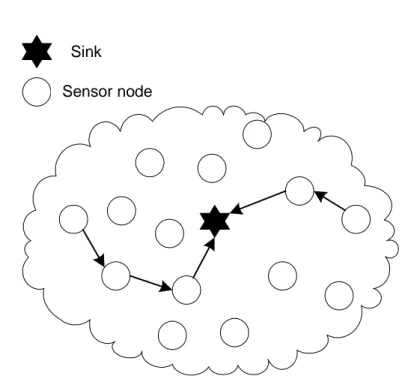
A common view of a sensor network topology is shown in Figure 2.1. The sen-sor nodes are scattered over an area represented by the cloud. It is a forwarding multihop sensor network, i.e., data travels, is forwarded, through several sen-sor nodes before reaching its destination. The sensen-sor nodes use a predefined routing scheme to communicate with other sensor nodes, i.e., how the data should travel in the network. The destination of the data traffic is often repre-sented by one or several sinks. A sink is the destination of the sensor nodes’ data, usually a high-performance computer connected to a wired backbone and with a wireless access point communicating with the sensor nodes. The sink is represented by the black star in Figure 2.1 and the arrows in the figure shows a possible data path (route) from a sensor node in the network to the sink. The sensor network topology is frequently changed due to sensor nodes disap-pearing from the network or new sensor nodes being added into the network.
2.3 Common view of the sensor network topology 15
Sink
Sensor node
Figure 2.1: A typical sensor network topology with sensor nodes scattered over an area. The sensor nodes communicate and forward other sensor nodes’ data to a sink placed somewhere in the network.
Having mobile sensor nodes also change the topology over time and the sensor network needs to handle these changes when they happen.
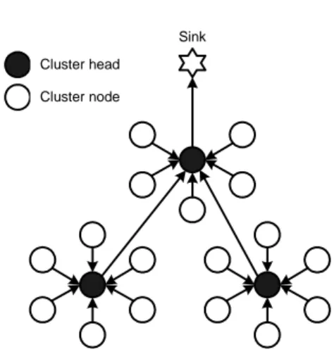
The typical sensor network topology in Figure 2.1 can be hierarchically divided and based on clusters, see Figure 2.2. One of the sensor nodes in a cluster becomes cluster head and the rest of the sensor nodes are called cluster nodes. The cluster nodes only communicate with the cluster head in their clus-ter. The sensor nodes not being cluster heads save energy because they only send their data to the cluster head, then they can turn off their radio in order to save energy, until they need to send again. A cluster node usually do not need to forward traffic from other sensor nodes. Being a cluster head is typ-ically more energy consuming due to the increased communication between itself and its cluster nodes. The cluster head needs to listen for data from all its cluster nodes, and possibly also to listen for data from other cluster heads
16 Chapter 2. Wireless sensor networks
Sink Cluster head
Cluster node
Figure 2.2: A typical hierarchical topology based on clusters. Sensor nodes communicate with its cluster head and the cluster head aggregates and/or fuses the received data before forwarding it to another cluster head or to the sink.
in the network. In order to distribute the extra workload of being cluster head, the task typically rotates among different sensor nodes in the network. In some sensor networks the sensor nodes’ clocks might need to be synchronized. For example when a TDMA2scheme is used in order to handle data communica-tion between the sensor nodes in the network. Two sensor nodes with exactly the same hardware will not have exactly the same clock frequency. The clocks typically deviate and cannot be synchronized perfectly and the clocks will over time drift apart. Therefore synchronization is needed between the sensor nodes in order to adjust the time in some applications.
2.4
Traffic reduction
In sensor networks using multihop, i.e., when data travels through several sen-sor nodes before reaching its final destination, the sensen-sor nodes can process the data collected from its cluster nodes locally before forwarding it. In the next sections we describe two common ways to process data in order to reduce the data traffic and data size in the network.
2.5 Challenges in sensor networks 17
2.4.1
Data aggregation
When multihop communication is used, e.g., as in the hierarchical topology de-scribed above, the sensor nodes can aggregate data collected from other nodes in order to reduce redundant data and thereby reduce the data traffic in the net-work [19]. If a cluster head and its cluster nodes have the same task in the network, e.g., measuring the surrounding temperature, they will probably send the same type of data to the sink. The data could, e.g., contain the sensed tem-perature, the cluster nodes’ ID and the destination address of the data. Instead of sending several different data messages to the sink the cluster head aggre-gates the data into a single data packet. The resulting data packet could for instance contain all the sensor nodes’ IDs and the sensed temperatures but only one of the same destination address is included in the data package. If several sensor nodes sense the same temperature they can be aggregated into one and further reducing the data packet.
2.4.2
Data fusion
If we continue the example from Section 2.4.1 but instead of reducing redun-dant information the cluster heads processes the data locally before sending the data packet further. The cluster head knows in advance that the user is interested in, e.g., the mean value of the surrounding temperature. Instead of sending a data packet with all the sensor nodes’ IDs and all the measured tem-peratures, it computes the mean value of the temperature locally. The data being sent contains the mean value and the sensor nodes’ IDs or possibly only an area ID. All the information needed to calculate the mean value of the tem-perature is the total sum, Σ, of all the measured temtem-peratures divided by the number,n, of measurements. If there are several cluster heads between the sending cluster head and the user and they all are sensing values for a mean value calculation at the user, the cluster heads in between can continue to fuse data if the first cluster head includes the numbern together with the mean value. This will reduce the size and the number of data packets.
2.5
Challenges in sensor networks
In this section we will discuss some challenges for sensor networks. Some specific challenges are:
18 Chapter 2. Wireless sensor networks
with each other, e.g., with radio or with infrared/laser. The communica-tion between nodes could be disturbed by external factors such as obsta-cles in line of sight when using infrared or, e.g., by other communicating nodes when using radio.
• Limited energy supply: Having wireless, adaptable unattended sensor nodes in harsh environments demands distributed algorithms to maintain the network. The sensor nodes have limited power supply and the sen-sor nodes need to conserve with the energy at their disposal. The most power-consuming activity is typically the communication between sen-sor nodes [26]. Hence, communication needs to be minimized in order to prolong the lifetime of the network as much as possible.
• Prone to errors: The sensor nodes are prone to errors [1, 33]. They could disappear due to fabrication errors, short-circuit caused by water leaks, lack of power or, e.g., animals/vehicles or humans breaking them. • Adaptable: The sensor networks need to operate in very dynamic envi-ronments and with dynamic changes of the network. They are left unat-tended after deployment and thus the networks need to be very adaptable to the environment. The task a sensor node performs may change over time and the networks need to reconfigure themselves and be task adapt-able, i.e., the sensor nodes might change the current task and perform another or get an additional task to the current one.
We address these challenges in papers A-C but sensor networks also have sev-eral other challenges not addressed in this thesis, for instance:
• Security: Some information from the sensor nodes should be protected. For example, the integrity of a patients’ health in a hospital is important. Information of the health state from the sensor nodes on a patient should not be able to be read by unauthorized persons. Having an ad hoc col-laborating sensor network in an area could for instance consist of several different sensor nodes from several different companies. Sensitive infor-mation might not be allowed to be forwarded by untrustworthy sensor nodes from other companies in the network.
Data from sensor nodes triggering an intruder alarm for example should not get lost or disappear in the network. Some applications, such as intruder alarms or safety applications, need to be able to rely on that the information sent to the sink actually will be received.
2.6 Sensor node architecture and design 19
• Ad hoc: Some sensor networks are situated in areas without infrastruc-ture and after deployment, connect to each other in ad hoc manners. The sensor nodes could for example be thrown out from an airplane over the area to be monitored or the sensor nodes could be mobile and move around.
• Identifier: The sensor nodes are often densely deployed and in some application areas global identifiers are missing. Instead of identifiers the sensor nodes with a certain task/attribute answer a question from a user. The data itself instead of the actual sensor nodes’ ID is of impor-tance, data centric. A question to the sensor nodes in the network could be: Where are the nodes with temperature above 25◦C? In other areas
the sensor nodes are divided into clusters where the cluster itself has an identifier but the individual sensor nodes have not.
The challenges described above introduce some energy tradeoffs to consider when optimizing the sensor network. A discussion on some of the energy tradeoffs are presented in Section 4.1.
2.6
Sensor node architecture and design
In order to meet the challenges and to be feasible to apply in the application ar-eas described in Section 2.1 and Section 2.5, the sensor nodes need to be cheap, consume very little energy [16], and also be able to operate in densely deployed areas as well as being adaptable and flexible. In this section we describe the sensor node architecture and the design of the sensor network in more detail.
2.6.1
Sensor node architecture
A typical architecture of a sensor node can be divided into four units; process-ing unit, sensprocess-ing unit, power unit and a radio unit that is able to both transmit and receive (transceiver), see Figure 2.3.
The onboard sensor unit consists of two subunits, sensors and analog-to-digital converter (ADC). The ADC converts analog signals from the sensors to digital signals used by the processing unit. There exists many different sensor types, such as [1]:
• seismic vibrations, low sampling rate magnetic, thermal, visual, infrared, acoustic and radar
20 Chapter 2. Wireless sensor networks Power Unit Transceiver Processor Storage Sensors ADC
Sensing unit Processing unit Radio unit
Figure 2.3: A typical architecture of a sensor node divided into four units.
monitoring a wide variety of ambient conditions like [11]:
• temperature, humidity, movement, light, pressure, soil make-up and noi-se.
The processing unit, usually a low speed CPU with small storage capabilities, performs tasks like routing, aggregation of sensed data etc. The transceiver unit communicates with the surrounding world and the power unit provides power to the other units. The power unit is typically a battery and an extra energy scavenging unit can be added to the battery, e.g., solar cells, prolonging the lifetime of the sensor node.
A mobility unit can in some cases be added to the sensor node as well as a localization unit, e.g., a global positioning system (GPS). All these units might need to fit into a combined unit small as a matchbox [9] or even within a cubic millimeter [35]. It is of great importance that all units together consumes a extremely small amount of energy in order to prolong the lifetime of the network. The sensor nodes should be able to operate unattended and be able to adapt to the current environment.
The desired cost of a sensor node should be less than one US dollar [27]. The sensor nodes need to be cheap in order to make unattended, densely de-ployed sensor nodes cost-justified compared to traditional sensors.
2.6 Sensor node architecture and design 21
2.6.2
The design of the sensor network
The sensor network design, as demonstrated, should reduce the installation cost and the network should be fault tolerant, scalable, flexible and self-organizing. As mentioned in Section 2.5, the sensor nodes are prone to errors and in most applications it is important that the network is fault tolerant and does not get affected by failing sensor nodes in the network [15]. Some of the sensor nodes in the network could be mobile or be moved by hand or by other external factors. Data should be rerouted through other sensor nodes if existing routes fail and adjacent sensor nodes could, e.g., take over the failing node’s task.
A typical network could span from hundreds up to thousands of sensor nodes in the network [30]. The network density can scale up to 20 sensor nodes/m2. In industrial applications where the sensor nodes, in for instance
monitor machinery, there can be 300 sensor nodes within 5 x 5 m2and 3000 in a 100 x 100m2[30]. The density is application specific, thus we need scalable
schemes to handle the dynamics in the sensor network. It is also important that the sensor networks are autonomous in handling the dynamics and reconfigure themselves when needed.
Some time after deployment of a sensor network in an area, new nodes need to be added to replace failing nodes. Flexible schemes handling new sensor nodes and re-arranging the network to the new conditions are necessary. There can be frequent changes in the network; sensor nodes can be jammed in some way or can not be reached, out of range, they malfunction or have no energy left. The task a sensor node should perform can change over time depending on the application. We need a self-organized network handling the changes in the network.
In some application areas, it is not important that the sensor nodes send their messages as in traditional address-centric networks, with ID and sensed value. In some applications, the areas where a certain phenomenon occurs, e.g., the areas where the temperature exceed 25◦C, are interesting. The sink
broad-casts the query and the sensor nodes with a temperature over 25◦C send back
a message to the sink. This type of communication can be either broadcasting-based or attribute-broadcasting-based. If it is attribute-broadcasting-based, the sensor nodes need to be divided into different attributes that are used as an identifier, attributes such as temperature, humidity, pressure etc. The sensor nodes could be divided into a geographic areas where the area is of importance/interest and not the sensor nodes themselves. If several sensors run the same task, e.g., monitor the same rolls on a machine, and any-casting is used they can all be associated with the same identifier. Not all of the sensor nodes need to be awake at the same time
22 Chapter 2. Wireless sensor networks
when using any-casting. Some of the sensor nodes can stay asleep until they are needed and only one of the sensor nodes associated with the identifier needs to answer the query.
2.7
Medium access mechanisms
In this section we briefly describe some important medium access mechanisms mentioned in the thesis. This section addresses readers not familiar with data communication protocols. The purpose of the medium access mechanism is to, e.g., avoid, reduce or handle communication collisions in the network.
2.7.1
Carrier Sense Multiple Access
The Carrier Sense Multiple Access (CSMA) protocol tries to detect the ab-sence of other traffic in the network before transmitting its own [32]. Using CSMA will not entirely prevent collisions. Different techniques exist to handle possible collisions and we will briefly describe two of them.
If two nodes try to send at nearly the same time using pure CSMA, none of them will detect the other’s carrier and a collision occurs. The nodes may detect that a collision has occurred if acknowledgements (ACKs) are used and the sender gets a timeout due to the absence of an ACK from the receiver. However, the nodes that are causing the collision continue to send their entire data packet, thus, wasting bandwidth.
CSMA with Collision Avoidance (CSMA/CA) uses a different strategy [8]. After a node ready for transmission has sensed the absence of other traffic, the node informs the receiver that it is intending to send. The receiving node replies back to the node if no other traffic is sensed. If traffic is sensed the transmitting node waits a random deferral time before informing again. The actual message is sent after getting a reply from the receiver. Collisions may occur with CSMA/CA when two nodes ask to send to two different receivers and the two receivers are not able to hear the other transmitting node’s message in time before both of them replies back. The delay time is increased when using CSMA/CA.
In CSMA with Collision Detection (CSMA/CD), the nodes sense for car-rier and start to send if there is no traffic. The nodes are able to detect when a collision occurs. When a collision occurs, the node sensing the collision stops to transmit its data immediately and sends a jamming signal instead. The node waits a random deferral time before trying again. Using CSMA/CD in wireless
2.7 Medium access mechanisms 23
networks is difficult since not all the nodes in the network can be assumed to hear all the others. Thus, e.g., the jamming signal may not be correctly received by all nodes.
2.7.2
Frequency Division Multiple Access
In Frequency Division Multiple Access (FDMA), the frequency spectrum is divided into several channels. The nodes use different channels to communi-cate without interference from other communicating nodes. Take the FM radio for instance, different radio stations send on different frequencies without dis-turbing each other. The user adjust the radio receiver to the station’s frequency he/she wishes to listen to. When frequency is divided, the bandwidth for each channel is reduced, hence, the data throughput is decreased.
2.7.3
Time Division Multiple Access
Instead of dividing the frequency, the time can be divided into cycles and slots as in Time Division Multiple Access (TDMA). A cycle consists of several slots and is repeated over and over again. Each node gets its own slot, i.e., a time frame, where it is allowed to send its data. The node starts at the beginning of its slot and need to finish before the slot ends. A node can get one or several slots each cycle. Using the radio example in the FDMA section, a typical radio broadcasting station can be seen as music songs played after each other mixed with commercials. The songs and commercials get the whole frequency band and do not disturb each other.
2.7.4
Code Division Multiple Access
In Code Division Multiple Access (CDMA), all the sensor nodes can use the whole frequency spectrum at all time [32]. Multiple data transmissions can simultaneously be transferred and the data transmissions are separated using coding theory. Each data bit time is subdivided into intervals called chips, typical 64 or 128 chips per bit. All sensor nodes get a unique code or chip sequence and they use this code to encode the transferred data. To send a 1 it send its code sequence and when sending a 0 it sends the one’s complement of the code sequence. The sensor node receiving the message decode the message using the sending sensor nodes’ code. The sensor nodes need to know all the other sensor nodes’ codes in order to decode the transmitted data.
Chapter 3
Existing infrastructure and
problem formulation
In this chapter we briefly explain what an existing infrastructure is and intro-duce the research area of this thesis.
3.1
Existing infrastructure
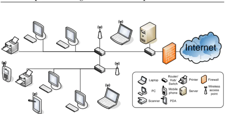
We define an existing infrastructure as a computer network together with its computers and peripheral equipments. Such existing infrastructures can be found in, e.g., hospitals and industrial buildings. The existing infrastructure have computers, laptops, Personal Digital Assistants (PDAs) and phones con-nected to a high-speed Local Area Network (LAN), see Figure 3.1.
Some of the computers in the LAN are regular Personal Computers (PCs). The PCs are often stationary computers, i.e., they are, e.g., workstations on a desk and static connected to the LAN by wire. Whereas laptops and PDAs often are mobile and can be either connected to the LAN by wire or wirelessly through a wireless access point. Phones using the network as carrier for con-versations can be either phones on the desk or wireless mobile phones using the wireless access points. In order to organize the network, computers are needed within the LAN. Some of the computers handle traffic flows and make sure that the data traffic reach its destination in the network. Other computers acts as file servers and their task are to store data, accessible for many users within the LAN. The data could be, e.g., patient journals, electrical
26 Chapter 3. Existing infrastructure and problem formulation
Internet
Laptop PC Scanner Printer Router/ Hub/ Switch Mobile phone PDA Firewall Server Wireless access pointFigure 3.1: An example of how a local area network in hospitals and industrial buildings could look like.
ics, source code or other shared documents. Some servers handle requests for email, print-outs and other network services from the users within the LAN. Some servers handle the accessibility to/from the Internet. The servers could if desired, stop the access to the LAN from user outside on the Internet or other LANs with a firewall. But they could still allow users within the LAN to access the Internet.
3.2
Background
Comparing the computers in existing infrastructure to the sensor nodes in sen-sor networks, the computers do not have scarce resources as the sensen-sor nodes. The computers have high-speed CPUs capable of running computation-intens-ive applications. They have plenty of memory where they, e.g., can store in-formation from computations, data and process states. Their power supply is “unlimited”1as they are connected to the mains and the network is typical a high-speed wired network designed for heavy traffic flows.
As the employees more and more get equipped with laptops and other pe-ripherals with wireless technology, we will certainly see an increased usage of wireless communications in hospitals and industrial buildings. The
employ-1For simplicity we will use the word unlimited throughout the thesis when talking about the
3.3 Problem formulation 27
ees do not need a fixed work desk with a stationary computer. The employees could for instance bring their computers from the work desk in their office to the meeting rooms and down to the laboratory, wirelessly connected to the companies’ LAN. It is our belief that the number of wireless access points will increase even more in the industrial and hospital environments as more and more electronic devices with wireless techniques are developed.
The industry forecasts an explosive growth in the use of sensor network applications in industry in the near future [3]. The sensor nodes in industry ap-plications are intended to replace traditional wired sensors. New apap-plications, and applications considered too expensive before or even not possible will now become possible. The sensor nodes will enlarge the application areas in the industry, adding low-cost and mobile sensor nodes in areas not cost-justified earlier.
3.3
Problem formulation
In this thesis we investigate if existing infrastructure, such as described above in Section 3.1, can aid in organizing a wireless sensor network scattered over a large area.
For example, consider two disjoint sensor networks performing the same task and delivering information to a sink within its own network. Remember that we in Section 2.3 said that, a sink in sensor networks usually consists of a high-performance computer with a wireless access point. Instead of sending the information to a sink each, the sensor nodes could send the sensed infor-mation through a close by access point in the LAN to one single shared sink. Some of the computers within the existing infrastructure could act as base sta-tions and help the sensor networks to organize themselves and, e.g., manage clock synchronization, routes and schedules. The base stations could handle tasks considered too energy consuming to perform for the sensor nodes them-selves.
A lot of the communication between sensor nodes in a purely sensor net-work is communication to maintain routes and topology changes. By central-izing the maintenance of data routes and topology changes/optimizations in a sensor network, we can prolong the lifetime of the sensor network. If the ex-isting infrastructure has knowledge about the whole network and has unlimited energy, it can perform optimizations not energy cost-effective in a purely sen-sor network by centralizing distributed algorithms like routing and topology changes.
28 Chapter 3. Existing infrastructure and problem formulation
Exposed sensor nodes forwarding data, can drain their batteries. Therefore, the sensor network needs to have routing algorithms adjusting the routes in order to distribute the workload. But to distribute the workload between the sensor nodes in the network, we need intelligent distributed algorithms and network information exchange between the sensor nodes in order to maintain the routes. Hierarchical topologies like clusters with cluster heads and cluster nodes might need to be rearranged depending on, e.g., the number of sensor nodes and the amount of energy in a cluster. In order to make these topology changes the sensor nodes need to communicate with each other. Our hypothesis is:
Centralizing communication-intensive algorithms like routing, cluster for-mation and sensor network optimizations will save energy and thus prolong the lifetime of the sensor network.
Chapter 4
The architecture of AROS
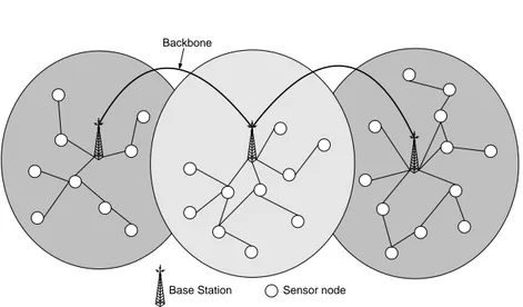
AROS, Asymmetric communication and ROuting in Sensor networks, see Fig-ure 4.1, is an architectFig-ure based on the problem formulation in Section 3.3. The architecture uses existing infrastructure as support for wireless sensor net-works. The infrastructure is mostly static, but there can exist mobile base sta-tions. The infrastructure is used to build base stations that help the sensor nodes with energy consuming tasks. The infrastructure can consist of regular com-puters, PDAs, cellular phones or small embedded systems. The base stations are connected to each other by wire, wirelessly or both, creating a backbone for the sensor nodes. The base stations have unlimited energy and long range wire-less communication capacity. Having unlimited energy, the base stations can always keep their radio on and listen for incoming data from the sensor nodes in their network. The base stations have high speed processors and plenty of memory, in comparison to the sensor nodes.
The sensor nodes in the network have scarce resources and the communi-cation range is therefore more limited than that of the base stations, because of the limited energy availability. In order to communicate with the base station some of the sensor nodes might need other sensor nodes to forward their data. The sensor nodes could be mobile and move themselves or be moved by hand, if the task changes over time. Some of the sensor nodes may run out of energy or could be moved out of radio range from the base station when moved. Other sensor nodes could malfunction due to fabrication errors, short-circuits etc.
The sensor network needs to be robust, dynamic and flexible. AROS sen-sor nodes’ use multihop forwarding in order to communicate with the base station and possibly, also with other sensor nodes in the network. By allowing
30 Chapter 4. The architecture of AROS
Backbone
Base Station Sensor node
Figure 4.1: The AROS topology with three base stations and scattered sensor nodes. The base stations are connected with each other in a backbone. Possible data paths from the sensor nodes in the cluster towards the base station are shown as an example.
multihop communication the area covered by one base station can be deter-mined by the range of that base station’s radio, rather than by the range of the sensor nodes’ radio. In order to reduce data communication in the network, an hierarchical layered topology is used with cluster heads and cluster nodes. The cluster heads should, if possible, aggregate or/and fuse data in order to minimize data traffic in the network.
4.1
Application tradeoffs
With the challenges described in Section 2.5 some energy tradeoffs need to be considered when optimizing/designing a sensor network. For instance, if the sensor network application is an application with high QoS demands, e.g., an intruder alarm, minimizing the delay-time for the data (alarm) from the sen-sor nodes to the sink might be the most important task for the sensen-sor network. The sensor nodes possibly consume more energy because they need to listen for traffic to forward or send data longer distances in order to reach the sink. High QoS in delivering important data to the sink might include that the sen-sor nodes need to send an ACK to the sending sensen-sor node after receiving a
4.2 The AROS vision 31
message, at the energy consumptions’ expense. Applications optimizing the sensor network for longevity might need to tolerate longer delay-time for the data to reach its destination. Mobile nodes in the network will increase the communication between the sensor nodes in order to maintain the network, hence consuming more energy. Safety issues also introduce energy tradeoffs. Encryption of data increases the workload of the CPUs at the sensor nodes and possibly increases the data size. Reliable data paths from a sensor node to the sink increase the communication needed in order to establish guarantees. The sensor node density could be of importance when sensor nodes forward data, in dense sensor networks, sensor nodes does not need to send their data long distances, hence, saving energy.
These are some examples of energy tradeoffs needed to be considered when optimizing the sensor network. Minimizing the delay-time could increase the energy consumption and minimizing the energy consumption could increase the delay-time. The energy tradeoffs need to be considered carefully depending on the application.
4.2
The AROS vision
Our vision is, by using existing infrastructure, the lifetime of the sensor net-works will be prolonged. By using existing infrastructure the communication exchange between the sensor nodes can be reduced and hence, the sensor nodes can save energy. Mobile sensor nodes changing cluster or changing from one base station to another, will be handled by the base stations instead of by dis-tributed algorithms performed by the sensor nodes themselves. The base sta-tion will, depending on the applicasta-tion, calculate the best energy tradeoffs for the sensor network, as described in Section 4.1.
The base stations in AROS have long radio coverage and instead of sensor nodes running complex distributed multihop clock synchronization algorithms, the clock synchronization can be handled by the base stations. The base sta-tions can handle routing issues for the sensor nodes and by, i.e., monitoring the sensor nodes’ energy level, the base station can change routes from sensor nodes with low energy levels to sensor nodes with higher energy levels. This will save sensor nodes from draining their energy when being highly exposed to forward data from other sensor nodes, and it will avoid data losses from vanishing routes. Topology changes and topology optimizations are handled by base stations with high-speed processors and plenty of memory. If the base station knows the energy level, the position and task of all the sensor nodes in
32 Chapter 4. The architecture of AROS
the network, it can perform topology optimizations not energy cost-effective if performed by the sensor nodes themselves. The base stations can communicate directly with the sensor nodes in the network. A query from a base station to a specific sensor node or region for instance, can be asked directly to the sensor node or region without involving other sensor nodes in between. The sensor nodes just need to focus on their assigned tasks until the base station inform them about task changes or/and topology changes they need to know about. If the sensor nodes know their tasks and when to communicate with each other, they can turn off their radio in between and thereby save energy.
In order for the sensor nodes to be able to turn off the radio in a forwarding sensor network without dropping data, knowledge about the communication between the sensor nodes need to be known in advance. One possible solution to enable predefined communication between sensor nodes is to use the TDMA protocol. The base stations can calculate a schedule for the sensor nodes and supply the sensor nodes with the information they need to know. To schedule a cluster-based sensor network with pure TDMA can increase the delay-time for data to be received at the base station from the outermost sensor nodes. The scheduler can, e.g., divide the spectrum into different channels like in FDMA, and dedicate a separate channel for each cluster. This makes it possible for several clusters to communicate in parallel and thus minimizing the length of the TDMA schedule. A combination of TDMA and FDMA could be a solution to some scheduling problems.
The base station could handle sensor networks with different types of ap-plication demands. Sensor nodes with low demands on the delay time can be mixed with sensor nodes with high demands on the delay time or they could be divided into completely different sub-networks. For example, the base sta-tion can divide the different sensor nodes into different sub-networks and build separate routes and schedules for different applications if necessary. Or, it can use cluster heads from one application with low interest of saving energy to forward data from sensor nodes with high interest of saving energy. Depend-ing on the application, the base station can calculate an optimal schedule with optimal routes and sub-networks for the sensor nodes.
As we mentioned earlier, the base stations have long distance communi-cation capabilities and are capable of transmitting data directly to all sensor nodes in their network. The sensor nodes on the other hand might not be able to communicate directly with its base station but need other sensor nodes to forward their data. We call this asymmetric communication and when all the sensor nodes in the network can communicate with the base station directly we call that communication symmetric.
Chapter 5
Related Work
In this section we discuss some related work and how they relate to the AROS architecture.
5.1
The LEACH project
LEACH (Low-Energy Adaptive Clustering Hierarchy) [14] and AROS are com-pared throughout the papers in this thesis. We have chosen to compare AROS to LEACH for a number of reasons. LEACH is a well known TDMA cluster-based sensor network architecture and the architecture is fairly simple to com-pare some of the most important aspects like energy usage per message and network lifetime. LEACH sends data frequently to the sink or base station without complex algorithms such as thresholds values, see Section 5.2. AROS can do all the things that LEACH can do and more. AROS can handle safety is-sues, routing of data, mobility, handover of sensor nodes from one base station to another, several different types of sensor networks, clock synchronization, reorganization of the sensor network and sensor network optimizations. In this thesis we have restrained AROS functionality to that of LEACH in order to be able to compare the architectures.
LEACH is a TDMA cluster based approach where a node elects itself to be-come cluster head by some probability and broadcasts an advertisement mes-sage to all the other nodes in the network. A non-cluster head node selects a cluster head to join based on the received signal strength. Being cluster head is more energy consuming than being a non-cluster head node, since the cluster
34 Chapter 5. Related Work
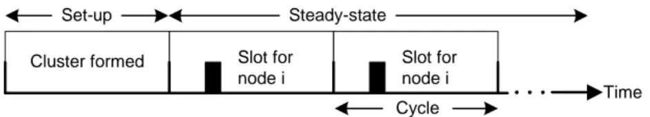
Cluster formed Slot for
node i Slot for node i Time Cycle Set-up Steady-state
Figure 5.1: The TDMA scheme in the LEACH architecture.
head needs to receive data from all cluster members in its cluster and then send the data to the base station. All sensor nodes in the network have the potential to become cluster head at some point in time. A TDMA round consists of one set-up phase and a steady-state phase. The TDMA scheme starts every round with a set-up phase to organize the clusters, see figure 5.1. After the set-up phase, the system is in a steady-state phase for a certain amount of time. The steady-state phase consist of several cycles where all sensor nodes have their slots periodically. The sensor nodes send their data to the cluster head that ag-gregates the data and send it to its base station at the end of each cycle. After a certain amount of time, the TDMA round ends and the network re-enters the set-up phase.
5.1.1
LEACH-C
LEACH-C (LEACH-Centralized) [13] has been developed out of LEACH and the basis for LEACH-C is to use a central control algorithm to form clusters. The protocol uses the same steady-state phase as LEACH. During the set-up phase, the base station receives information from each sensor node about their current location and energy level. According to [13], the sensor nodes may get their current location by using a global positioning system (GPS) receiver that is activated at the beginning of each round. After that, the base station runs the centralized cluster formation algorithm to determine the clusters for that round. To determine clusters and select cluster heads, LEACH-C uses simulated annealing [23] to search for near-optimal clusters. Once the clusters are created, the base station broadcasts the information to all the sensor nodes in the network. After receiving the message the sensor node goes to sleep until it is time to transmit data to its cluster head.
5.2 TEEN and APTEEN 35
5.1.2
LEACH-F
A further development is LEACH-F (LEACH with Fixed clusters) [13], which is based on clusters that are formed once in the first setup-phase - and then the clusters remain fixed. After clusters have been established, the cluster head position rotates among the sensor nodes within the cluster. The advantage with this is that, once the clusters are formed, there is no set-up overhead at the beginning of each round, no extra communication from the base station is needed. To decide clusters, LEACH-F uses the same centralized cluster formation algorithm as LEACH-C. The fixed clusters in LEACH-F do not allow new nodes to be added to the system and do not adjust their behavior based on nodes dying. Furthermore, LEACH-F does not handle sensor node mobility.
5.2
TEEN and APTEEN
TEEN, Threshold sensitive Energy Efficient sensor Network protocol [21] is an extension of the LEACH project, described in Section 5.1. TEEN is a time critical protocol best suited for time critical applications. The protocol is, as LEACH-C, cluster based with base stations maintaining the cluster head group-ing. The base station can communicate directly with the sensor nodes but the sensor nodes are, as in AROS, not always able to communicate directly with the base station.
The TEEN protocol introduces a hard and a soft threshold. The hard thresh-old is a threshthresh-old value a sensor node needs to sense before sending data to the cluster head. For instance, sensor nodes sensing temperature need to read 25◦C before sending data to the cluster head. The soft threshold is the maximum dif-ference the value is allowed to differ from the hard threshold before sending data to the cluster head. For instance, once sensing 25◦C the temperature must
differ ±2◦C before sending a new data to the cluster head. The sensor node do
not send any data until sensing the hard threshold value leaving the base station ignorant of the sensor nodes’ state. The base station can not assume that the sensor nodes are alive and working if it does not get data from the sensor nodes. Even though the sensor node is not sending data to the cluster head, it senses its surroundings and possibly it even performs some sort of computations using energy.
TEEN differs from AROS in several ways. Once the hard threshold has been reached the sensor node turn on its radio and sends the data to the base sta-tion. Collisions might occur between concurrent communicating sensor nodes.
36 Chapter 5. Related Work
The authors say that to avoid collisions between concurrent communicating sensor nodes, TDMA scheduling or CDMA could be used. Using TDMA will increase the delay time for the data to be received at the base station. The life-time of the sensor network in TEEN depends on how often the cluster nodes communicate with the base station. The number of collisions in the network increases as the communication increases. Intensive communication can even increase the amount of energy used per bit, compared to the LEACH architec-ture.
The cluster heads in the network send out data with hard and soft threshold attributes to the sensor nodes. In AROS the base station handles all communi-cation to the sensor nodes in the network. Further, the cluster heads in TEEN can not turn off their radio as AROS’ cluster heads can. The cluster head in TEEN can receive data from its cluster nodes at any time. In AROS the cluster heads know when the cluster nodes send their data, and thus, the cluster heads can turn off their radio when not scheduled to receive or transmit data.
APTEEN, Adaptive Periodic Threshold sensitive Energy Efficient sensor Network protocol [22], uses the same architecture described above and the cluster nodes can be scheduled to send data periodically to the base station. As in TEEN, the cluster heads distribute the schedule to its cluster nodes. APTEEN uses TDMA to schedule the cluster nodes, eliminating the radio col-lisions between cluster nodes. Thus, increasing the delay time in the network for time-critical data. The clusters use different CDMA codes in each cluster an a commonly used code to talk to other cluster heads and the base station. The cluster heads can not turn off their radio in APTEEN since another cluster heads can transmit data any given time.
Comparing TEEN and APTEEN to AROS could be useful if the AROS architecture only suppose to handle realtime applications. However, AROS can handle several types of applications. Therefore, we choose to compare AROS to LEACH since we are interested in minimizing the energy used per bit in the network.