Designing a fault tolerant and secure
network core for inter-organization
communication
Mälardalen University
Academy of Innovation, Design and Engineering Abtin Hassani
han03007@student.mdh.se Civil engineer
20 May 2015
Examiner: Mats Björkman Advisor: Mats Björkman
Abstract
Service providers which provide services within customers’ networks often deal with the issue of needing to use a large number of VPN accounts and RSA tokens to access customers’ networks. One service provider (SP) has solved this by setting up an inter-organizational communication network (IOCN) to facilitate access to customer places systems. This system has out grown its original setup. Research on network architectures is abundant but there is very limited research focusing on IOCNs. The aim of this thesis has been to contribute to the lack of that research by intending to redesign the above mentioned IOCN with focus on ensuring network security and fault tolerance. This was done by analyzing the existing IOCN, evaluating its flaws with regards to network security and fault tolerance and finally suggesting a new setup based on the original infrastructure. The solution has been generalized to be adaptable to the needs of any service provider. The infrastructure has been setup with a cascading firewall structure increasing security by using generalized rules on the outer firewalls and specifying rules further in to the network.
Keywords
Inter-organizational communication network, IOCN, Inter-organization communication, IOC, Data center network, DCN, cascading firewalls, network security
Table of Contents
1. Introduction ... 5 1.1 Previous Research ... 6 1.2 Problem ... 6 1.3 Research Question ... 6 1.4 Limits ... 6 2. Ethics ... 6 3. Method ... 64. Understanding the current IOCN ... 7
4.1 Network classifications ... 7
4.2 Inter-organization Communication (IOC) Services ... 8
4.3 Network Address Translation – NAT ... 10
4.4 Third-party VPN ... 11
5. Risk Analysis of current IOCN ... 11
5.1 Structural Risks to the infrastructure... 11
5.2 Security Risks ... 12
6. Result ... 12
6.1 Requirements ... 13
6.2 Choice of equipment brand ... 13
6.3 Options for Remote Access Services ... 13
6.4 Network classes ... 13
6.5 Setup of Remote Access Services ... 14
6.5.1 Remote Access Wan Connect ... 14
6.5.2 Remote Access IPVPN ... 15
6.5.3 Remote Access Internet Connect ... 16
6.5.4 Customization of RAIV & RAIC ... 16
6.5.5 Remote Access L2L ... 17
6.5.6 Third-party Remote Access ... 18
6.6 Overview of Remote Access ... 18
6.6.1 Firewalls ... 19
6.6.2 VPN Routers ... 19
6.7 Network Zones ... 20
6.8 Physical Setup and Fault Tolerance ... 21
6.8.1 Geographical Fault Tolerance ... 22
6.8.2 Gateway Redundancy ... 24
6.8.3 Service Provider Fault Tolerance ... 24
6.8.4 Fault Tolerant Power supply ... 25
6.9 Security and Traceability... 25
6.10 Substituting brand specific functions ... 25
7. Discussion ... 25 7.1 Related work ... 26 8. Conclusions ... 26 8.1 Future Work ... 26 References ... 28 Abbreviations ... 31
List Of Figures
Figure 4-1 Infrastructure overview ... 7
Figure 4-2 Traffic flow RA Internet & IPVPN ... 9
Figure 5-1 Remote Access Physical overview ... 12
Figure 6-1 Remote Access WAN Connect ... 15
Figure 6-2 Remote Access IPVPN ... 16
Figure 6-3 Remote Access Internet Connect ... 16
Figure 6-4 Remote Access L2L ... 18
Figure 6-5 Third-party VPN... 18
Figure 6-6 Remote Access overview ... 20
Figure 6-7 Remote Access optimized overview ... 20
Figure 6-8 Inter-network communication ... 20
Figure 6-9 RA Simple Physical Setup ... 21
Figure 6-10 RA with switch redundancy ... 22
Figure 6-11 Dual Site Remote Access ... 23
Figure 6-12 Remote Access Layer 2 Connections ... 24
1. Introduction
The last two decades companies have started outsourcing more of the peripheral services they are dependent on but which are not part of their core business. Management of various applications and service are instead provided by companies with core focus and expert knowledge within the area. For the companies providing the services this creates a need to facilitate methods of accessing equipment, applications and services places inside customers’ networks.
In the past one of the ways service providers (SP) have been granted access is physical onsite access to the equipment. However, this method is neither practical nor cost efficient when not absolutely necessary.
Another solution is accessing remotely using protocols like RDP, secure shell (SSH) or even Telnet. The problem faced when connecting remote is security. Since most, if not all, companies have an Internet connection to their offices, using that connection can be very practical and cost efficient. Exposing systems directly to the Internet poses several severe security issues [1],[2],[3],[4].
The need for the connection to be secure is vital. As this is a link into customers’ networks and risks exposing the company to outside threats [2],[3],[4], if not set up properly. When a hacker wants to attack a company they will try finding vulnerabilities from all angles. This can be directly attacking the company through their users or their public systems, like homepages etc. Another method is to target service providers or subcontractors and use their links in to the company. This creates a need for SPs to ensure not only security in their own networks, but also ensure security in the communication to and from customer networks.
To avoid giving unauthorized people the opportunity to try accessing the equipment, they should not be openly available on the Internet.
Secure user access could be solved by using Client Virtual Private Network-solutions[5], such as provided by Cisco or Checkpoint. But for a SP of with a large number of customers this has several problems.
- Cost efficiency
Each account has a license cost. The SP has a lot of technicians who work with a lot of different customers. Using a unique account with certificate or RSA-token for each technician will lead to high costs for either the customer or the SP.
- Security & Traceability
An alternative could be to use a generic account with a certificate or RSA-token for all technicians. The problem with this would be the difficulties tracing what user actually used a session. It is also common for such VPN [2],[5] clients to restrict usage to one simultaneous user at the time for each account.
- Surveillance and Statistics
For the surveillance systems to work properly, a constant connection in needed. This cannot be accomplished with a client VPN connection.
- Administration
With a great number of technicians and customers the administration of VPN accounts is time consuming. Time which could, instead, be used for providing the service.
1.1 Previous Research
As mentioned earlier, research on various Data Center Network (DCN) solutions has been carried out. Wang et al. paper [6] gives a summary of structures of DCNs and protocols used to optimize communication and allow for scalable networks.
In an attempt to reduce cost and gracefully scale DCNs D. Lin et al. have in their paper [11] proposed a data center interconnect (DCI) architecture based of DCell and BCube, both of which are recursively defined architectures.
Though the proposed architectures solve many of the problems of fast growing DCs they do not address the security aspect which is critical in multi-tenant network environments.
N. Smith’s and S. Bhattacharya’s research on firewall placement in large network topologies suggest a solution of cascading firewalls [Cascading] to layer the security and gradually tighten access the further in to the network traffic reaches.
1.2 Problem
Research has been done to enhance fault tolerance and increase performance in core networks such as DCN, LAN [6],[7],[8] and harsher environments [9]. Some suggest developing new protocol for routing & switching in core networks or scalable network topologies for data centers with a large number of hosts. Other research has focused on secure corporate networks over public networks [10]. However research on core network for inter-organizational communication is limited.
This paper aims to address this lack of research and contribute to the existing research on how to create fault tolerant and secure core networks by analyzing a core network for inter-organizational communication but instead of developing new protocols, using the existing technologies and redesigning the network architecture
This I aim to do by answering the research question. 1.3 Research Question
How does one design a fault tolerant and secure network core for inter-organizational communication?
1.4 Limits
The analysis of the existing solution will be limited to security of the network and fault tolerance of the services.
2. Ethics
All data collected during the study has been with the full knowledge and permission of the company where the study was conducted. The data has been handled in a secure manner has been kept confined to equipment approved by the company. The company has chosen to remain anonymous. The report has therefore been reviewed and edited in cooperation with representatives of the company to ensure that no sensitive
information has been presented.
3. Method
Data collection has been done by reviewing existing documentation, performing a technical analysis of the system both by tracing equipment through CLI and following
physical cabling. Additionally interviews have been done with administrators of the system. The interviews have mainly consisted of following and observing the administrators in their work in addition to asking questions when needed.
Using the collected data an analysis of the flaws in the current infrastructure has been done. By identifying the types of communication the various systems need, a set of zones been defined. The zones have in turn been classified into security levels and an infrastructure has been designed to separate them as needed.
4. Understanding the current IOCN
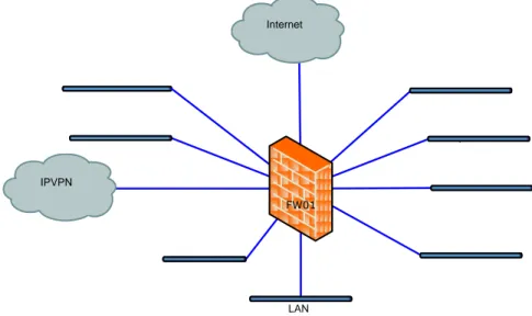
The network is divided into a number of De-Militarized Zones (DMZ). Each zone has a specific purpose with separate permissions for accessing customer networks and each other.
As illustrated in Figure 4-1 the heart of the current infrastructure is a firewall (FW), where each network terminates. In this firewall the SP regulates access between the DMZs and with what protocol.
Internet
FW01 IPVPN
LAN
Figure 4-1 Infrastructure overview 4.1 Network classifications
The current DMZs can be divided into five general categories to better describe their use.
External SP servers
Wide Area Network (WAN)
User Access
Customer Connection
Internal Communication
External SP Servers
The External SP server DMZs are networks which hosts servers which are used for communication with various customer equipment. These can be Terminal servers for accessing customer equipment, surveillance servers for monitoring customer equipment, or centralized management and backup servers for customer equipment.
SurveillancDMZ
COMDMZ
ExternalDMZ
PublicDMZ
ThirdPartyVPN
WAN
Public Networks refers to networks that are connected to an infrastructure where the SP does not have full control. These outside networks can pose a security risk to the SP.
Internet
RA-IPVPN
User Access
User access networks are network from which the SP’s users and technicians access the IOCN. That is, the desktop stations where they work from. This access can either be directly from the corporate network through the “inside” DMZ or through a Virtual Private Network (VPN) connection from inside or outside the company network.
Inside
Customer Connection
Customer Connection networks are networks meant for core IOCN equipment. The core equipment’s management interface is on these networks. Traffic to access the equipment, which should be managed, from here on called “the customer networks”, come in through the following DMZs:
CustZone
Onecompany-dmz
TransitDMZ
Internal Communication
Internal communication networks are networks for the purpose of allowing restricted communications with DMZs without exposing them too much to external or internal communication.
I-vpn
iLO
4.2 Inter-organization Communication (IOC) Services
The network consists of different setups with different levels of security and cost where each suits various customers’ needs. The services will here on out be called “Remote Access” (RA) services. The five main services are:
Remote Access Internet Connect (RAIC)
Remote Access IPVPN (RAIV)
Remote Access Lan-to-Lan (RAL2L)
Remote Access WAN Connect (RAWC)
Remote Access ISDN (RAISDN)
Remote access Internet & IPVPN Services
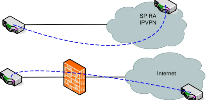
The customer accesses through Internet and IPVPN [5] are, together with a deprecated ISDN solution, the original setup for the RA. Connected to the central firewall, through “TransitDMZ”, are two routers, RA VPN Gateways (RAVG), which are used as VPN gateways. The purpose of these routers is to set up seamless secure connections from the IOCN infrastructure to equipment places at the end-customer. The RAVGs are
connected to the “TransitDMZ”, “i-vpn” and “RA-IPVPN” DMZs. From each of the RAVGs IPSec is set up encapsulating a GRE-tunnel to each customer places router (RA router). IPSec is used for encryption of the data [13] and GRE is used to enable routing over the tunnel [14]. The tunnels with the traffic to and from customers flow to the interface on the “RA-IPVPN” or “i-vpn” DMZ, while the unencrypted, non-encapsulated data flows on the “TransitDMZ” DMZ to the firewall to access the rest of the IOCN, Figure 4-2.
Internet SP RA IPVPN
Figure 4-2 Traffic flow RA Internet & IPVPN
Remote Access Lan-To-Lan Service
In some cases where the customer prioritizes having a cheaper solution rather than high availability they can request to use a connection type called LAN-To-LAN (L2L). This is simply an IPSec encryption tunnel [13] set up between one of the SP’s RAVGs and a customer’s equipments. This, however, comes with responsibilities for the customer to manage the translations of the NAT-addresses assigned to them by the SP, so as to not overload RAVGs with NAT translations.
This solution is also used when customers have policies that prevent third-party equipment in their networks.
Traffic flow for RA Internet Connect & L2L Services
The “i-vpn” DMZ is used to connect to customer placed equipment which are accessed through the internet. As shown in Figure 4-2, the traffic for the tunnel flows from the RAVGs, through the “i-vpn” DMZ to the central firewall. The Firewall filters so that only IP-SEC and GRE traffic is allowed between the Internet and the VPN gateways. From there the tunnel traffic flows to the “Internet” DMZ on to the Internet.
Traffic flow for RA IP-VPN Service
The MPLS network is considered a more secure network than the Internet, since it is not a public network, but instead a network set up exclusively for accessing customers from the SP. For this reason the RAVGs are connected directly to the IPVPN network without having to pass through the firewall.
Remote Access WAN-Connect Service
By connecting to the customers WAN, as just another customer’s office, the Service provider can reach all the equipment connected to the WAN (IPVPN). This is useful when the equipments managed by the SP are distributed among several customer sites. This requires the customer to have a level of trust for the SP to allow the possibility of reaching everything in that IP-VPN network which is not protected, for instance by a firewall.
The customers’ IPVPNs are handed over by the IPVPN service provider, in this case the same SP, each on a separate VLAN. The VLANs are connected to a firewall context (a virtual firewall) which makes sure each customer’s traffic is kept apart.
This allows for a RA to be set up, without any additional hardware needed for each customer.
Deviating Solutions
The SP has two key customers which they provide services to. This paper will call them “Key Customer 1” (KC1) and “Key Customer 2” (KC2). Both these customers were set up before the RAWC solution was in place and do not necessarily use the SP as a WAN provider and have therefore had individual solutions set up for them, to guarantee high availability to their systems from the SP.
Key Customer 1
KC1 is set up in a similar fashion to WAN connect, in the sense that two redundant connections from the service provider have been provided. These are terminated in the provider’s equipment, which run Hot Standby Redundancy Protocol (HSRP) [27] as part of the redundancy. Connected to the provider equipment the SP has two switches, also running HSRP. The switches in turn have two FW connected, with failover, connected to them.
Key Customer 2
This access is structured more like the IP-VPN Service, with a router that terminated IPSec and GRE tunnels. The WAN is the customers IPVPN, which is provided by the SP. The traffic is filtered through a dedicated FW for these access methods and finally sent through the central RA FW.
ISDN
As part of the original solution connections were set up with ISDN. The reason for this is that when the solution was set up the access to broadband and IPVPN connections where limited and expensive.
This access will not be explained further since the SP intends to remove it. 4.3 Network Address Translation – NAT
The SP accesses equipment in many customers’ networks. Each of the networks usually has their own IP-schemes that cannot be integrated into the SP’s network address scheme. As a standard most companies use private address schemes for their internal networks. This is done to avoid wasting public IPv4 addresses since they are in short supply [15]. As there are no regulations of private addresses and multiple parties can use them as they wish, which results in of address conflicts when the SP connects to these customer networks.
To resolve this issue, the SP has chosen to use its own address scheme. By using a small subnet of private addresses for each customer and then translating the customer addresses to the addresses chosen by the SP. This is in most cases done in the SP owned equipment as close to the customer as possible to avoid IP-address conflicts.
This, however, does not apply when the customer is using a public address scheme. As there is no risk of address conflicts, it is kept as simple as possible, and no address translation is applied.
The translation inadvertently leads to an extra layer of security [16], since equipment that has not had any of their addresses translated, will not be able to communicate with any of the SP’s equipments other than the RA router or RAWC FW-context.
In cases where the customer does not allow third-party IP-networks to be routed in their network there are two solutions used. If traffic only needs to be initiated from the SP a NAT-overload is used.
In the case where customer placed equipment needs to initiate traffic to the SP the customer is required to provide a range of IP addresses for translating the SP’s addresses.
In some customer solutions where the customer’s address schemes do not overlap, and fit the SP’s address scheme NAT has not been used.
4.4 Third-party VPN
The SP has a number of subcontractors. They can be used for managing specific customer systems, where the SP lacks in-house expertise, or at times when the SP needs help with internal systems.
The third party technicians set up a VPN session to a router. When third-party VPN users connect they are each assigned a specific IP-address each time. Depending on what the technician is supposed to be able to access, rules are manually configured for the IP address which they have been manually assigned.
5. Risk Analysis of current IOCN
There are a wide range of risks to a network [1],[2],[3],[4],[17],[18],[19]. In this paper we will divide them into two different categories, structural risks to the infrastructure with a focus on fault-tolerance and security risks to the infrastructure and its connected systems.
5.1 Structural Risks to the infrastructure
Structural risks are weaknesses in the architecture which undermines the stability of the network. By identifying a “Single Point of Failure” (SPOF) measures can be taken to mitigate the weakness. A SPOF is when a whole system, or subsystem, is dependent on a single unit. In this case unit can be a switch, router, firewall or physical connection. If that unit should fail, the functionality of the whole system, or subsystem, will fail. This will be done by analyzing the fault tolerance of the functionality of each unit on the three first layers of the OSI model, physical, data link and network [28].
SPOFs on the Physical Layer
Internal Zone Transit Zone External Zone Open external Zone
Red
acte
d
Figure 5-1 Remote Access Physical overview
SPOFs on the Data Link Layer
This paragraph has been redacted.
SPOFs on the Network Layer
This paragraph has been redacted. 5.2 Security Risks
Protecting networks and their systems becomes more important all the time. On open networks, like the Internet, threats and attacks continuously increase [1],[2],[3],[4] ,[17],[19].
Security in customer placed equipment
This paragraph has been redacted.
Authentication
This paragraph has been redacted.
Network Architecture
This paragraph has been redacted.
DMZs
This paragraph has been redacted.
Firewall Rules
This paragraph has been redacted.
NAT
When the SP translates the IP-addresses of the customer placed hosts (CPH) the translation inadvertently leads to an extra layer of security [16], since equipment that has not had any of their addresses translated, will not be able to communicate with any SP equipment further into the SP’s network than the one closest to the customer.
6. Result
This section will, in a number of steps, form and present a recommended setup. It starts with a discussion about choice of brand for the network equipment and will then
go on to define four classes of networks and go on to present a setup of each RA service and identify the types of equipment needed to make it up with consideration to the network classes. The setups will then be merged into an overview concept of the IOCN and unnecessary redundancies will be removed. Network zones for internal and external communication will be identified and defined.
6.1 Requirements
For SP systems communicating with customers it is strongly recommended to use public IP-addresses. This ensured that, while there might be IP-address conflicts between two customers, there will never be an IP-address conflict between the SP’s and the customers’ IP-addresses. An alternative could be to translate the SP’s addresses to a network range of each customer’s choice, but this increases work overhead and complexity to the system.
6.2 Choice of equipment brand
Since a solution like this has a cost which will affect the pricing of the services the company offers, the additional requirement of cost awareness is added for consideration:
Equipment cost of the Central infrastructure.
Administration cost for setup and maintenance.
Cost of adding new customer to the solution.
Cost of outages caused by less suited cheaper equipment
In this study we will use Cisco, but any equipment that has the same or equivalent functionalities can be used. This will be described in section 6.10. The drawback with using Cisco equipment is the cost. Cisco generally tends to be more expensive, but ensures high quality hardware and support.
6.3 Options for Remote Access Services
Different customers have different demands on security and their ability to invest resources in the RA connection can also vary. The SP must therefore offer a variety of solutions to fit a large variety of customer.
6.4 Network classes
To ensure a high level of security in the infrastructure the security classes of the various networks will be determined. The security class will be determined by the level of control the SP has over the network and the amount of filtration the traffic has been subjected to.
The four classes of networks are:
Internal networks, Security class 1 (high)
Transit networks Security class 2
External networks Security class 3
Open external networks Security class 4 (low)
Internal networks are networks which hosts a service either aimed at communicating with customer equipment, other internal systems or users clients.
Transit network does not host any service but instead is only an intermediary network mean to transport traffic to and from other networks.
An External network is meant for communication with other parties than the SP. It is a network where the SP does not have full physical control of the end equipment and their locations. This can be secure customer networks.
Open external networks are public networks which any person or entity can communicate. A typical example of this is the Internet.
Communication between networks needs to live up to these criteria:
Communication between two internal networks must pass through a layer of security control.
No communication originating from an Internal network destined to a Transit network is allowed.
No communication originating from a Transit network destined for an Internal network is allowed.
No communication originating from an Internal network destined to an Open external network is allowed.
No communication originating from an Open external network destined for an Internal network is allowed.
Communication originating from an internal network destined for an External network must pass through at least one layer of security control.
Communication originating from an External network destined for an internal network must pass through at least one layer of security control.
Communication originating from a Transit network destined for an Open external network must pass through at least one layer of security control.
Communication originating from an Open external network destined for a Transit network must pass through at least one layer of security control.
No communication originating from a Transit network destined for an External network is allowed.
No communication originating from an External network destined for a Transit network is allowed.
No communication is allowed between two Transit networks.
No communication is allowed between two External networks
No communication is allowed between two Open external networks.
No communication is allowed between an External network and an Open external network.
To minimize confusion a clarification is made. Traffic originating from an equipment and traffic incoming from equipment must be differentiated. Traffic can originate from an External network, but can be incoming to an Internal network from a Transit network.
A layer of security can consist of filtering of traffic by a FW, access-list or equivalent. Until we have defined all Internal networks they will hence forth be called “SP Networks”.
6.5 Setup of Remote Access Services 6.5.1 Remote Access Wan Connect
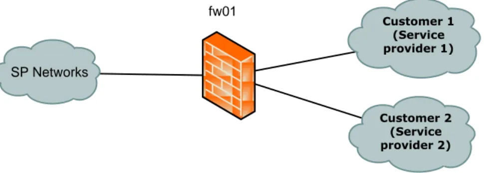
The Wan Connect Solution has had a well thought through setup from the start. What has not seemed to be considered is connecting additional IPVPN service providers to this solution to give customers with other providers the option of using this solution. This will be done simply by extending the WANs for customer’s with other providers to the same FWs terminating the customers’ IPVPN networks. In the WC FW static 1-to-1
NAT rules will be defined for each host which needs to be accessed from the SP. Routes will be minimalistic and only defined for necessary customer network segments or single addresses so as to maximize number of customers in a firewall context without getting IP-addresses collisions. From the WC FWs the traffic with the translated addresses will be sent on to the SP’s Network. The customer specific solutions for “KC1” and “KC2” will be integrated into this solution, but this paper will put no more focus into these customer solutions.
To make this solution scalable equipment which supports hosting virtual firewalls (VFW) can be used [23],[24]. This will enable the possibility to simply deploy a new VFW whenever needed. With basic functionality, like NAT, routing and general filtering, needed of the FWs load should not be an issue.
Network Classifications
The customer IPVPN networks, to the right in Figure 6-1, are classified as External networks. This is since they are in the customers secure zone but the SP does not have full control of the network.
The link from fw01 to the left is classified as a Transit network.
fw01 SP Networks Customer 2 (Service provider 2) Customer 1 (Service provider 1)
Figure 6-1 Remote Access WAN Connect 6.5.2 Remote Access IPVPN
A SP owned router will be placed at the customer location. The WAN interface will be directly connected to the IPVPN. The customer placed router (CPR) will be set up with VPN tunnels using GRE over IPSec encryption to the RA VPN GWs. When traffic from the CPH is sent to the VPN interface the addresses are translates using static 1-to-1 NAT. To increase security the VPN GWs for the RA IPVPN will be separated from the WAN by a firewall. The firewall will be configured to let through IPSec and GRE traffic. In addition to these protocols traffic like “echo-reply”, which is replies on ping echo requests, and similar ICMP traffic can be allowed. The traffic which comes from the VPN tunnels then flow to the central RA FW where traffic filtering is done. The CPR is configured with a loopback address for management.
Network Classifications
The SP RA IPVPN, to the right in Figure 6-2, is the SP’s WAN for RA connections; however the endpoints of the network are spread out among a large variety of customer locations. Since the locations are geographically separated from the SP the WAN will be classified as en External zone. The VPN tunnel from the CPR to the VPN GW, marked with the dotted blue line, the connection from the FW to the VPN GW and the connection from the VPN GW into the SP’s Network are all classified as Transit networks. Traffic originating from CPH on the CPR LAN interface is classified as External Traffic.
IPVPN r03
r01 SP Networks
FW
Figure 6-2 Remote Access IPVPN
6.5.3 Remote Access Internet Connect
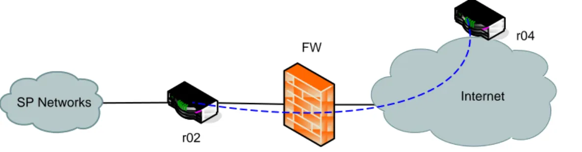
The RAIC is virtually identical to the RAIV. The only difference in its basic configuration is that instead of the WAN interface of the CPR being connected to the SP’s IPVPN it is connected to the Internet.
Network Classifications
Just as with the RAIV solution the VPN tunnel from the CPR (r04) to the VPN GW (r02), marked by the dotted blue line in Figure 6-3, the connection from the VPN GW to the FW and the connection from the VPN GW into the SP’s Network are all classified as Transit networks. The Internet however, is a publicly available network and is hence classified as an Open external network. Traffic originating from CPH on the CPR LAN interface is classified as External Traffic.
Internet r04
r02 SP Networks
FW
Figure 6-3 Remote Access Internet Connect
6.5.4 Customization of RAIV & RAIC
Each customer has their own policies and circumstances for their network which requires some flexibility of the solution. Such as allowing providers equipments direct access to networks segments or requiring them to pass the customer FW.
WAN Connection
The WAN connection of the CPR in the RAIV service fixed. It will in every case be directly connected to the SP’s RA IPVPN.
The RAIC is however more flexible. Since the internet connection and the IP-addresses for the WAN interface belong to the customer it needs to adapt to the customers’ requests and policies. The basic configuration is that the WAN interface of the CPR is directly connected to the internet. However at times customers have a DMZ where they place equipment which meant to communicate with the Internet. In these cases the customer needs to allow IPSec and GRE traffic to and from the CPR, in addition to that SSH also needs to be allowed to the CPR. It is up to the customer to decide how strict the rules need to be. They can allow the traffic for those protocols for any addresses, limit
the access the SP’s address range or even specify exactly which of the SP’s addresses will be allowed.
There are a few rare cases where the customer does not have any public IP-addresses to spare. In these cases the CPR is placed behind a customer an existing firewall, with a public IP-address, and assigned a private IP-address. Port address Translation (PAT), also called Network Address Port Translation (NAPT) or Network Address Translation-Port Translation (NAT-PT) [16],[25] is then used to direct incoming IPSec and GRE traffic to the CPR. Unfortunately this works poorly and if it works only one VPN tunnel can be set up [10],[25].
LAN Connection
The LAN interface of the customer placed router can therefore be connected either directly to the subnet with the host the SP needs to manage or to a separate which then passes through the customer FW to reach the CPH. A consideration to make is that hosts on the customer’s network segment usually have a customer own equipment set at default gateway (DGW). This in turn requires the hosts to be configured with a static route for the SP’s management address range to the SP’s router if the router is on the same network segment. An alternative to this is for the customers DGW to be configured with a route for the SP’s address range to the SP router.
NAT
There are a few cases where it is not necessary to translate the IP-addresses of the CPH. These are usually cases where the customers use Public IP-addresses CPH. Another circumstance is when the customer’s IP-scheme fits the IP-scheme of the SP.
Routing of SP IP-addresses
Organizations with stricter network policies at times do not allow routing of outside IP-addresses in their networks. This means that the CPH will not have a path to the SP’s centralized infrastructure.
If the customer places hosts never need to initiate traffic to the SP, this can simply be solved by using NAT-overload on the LAN interface.
If, however, there are times when the CPH initiate traffic to the SP’s centralized infrastructure, the customer needs to provide the SP with a range of IP-addresses which the SP can use to translate its own addresses to when communicating with the CPH.
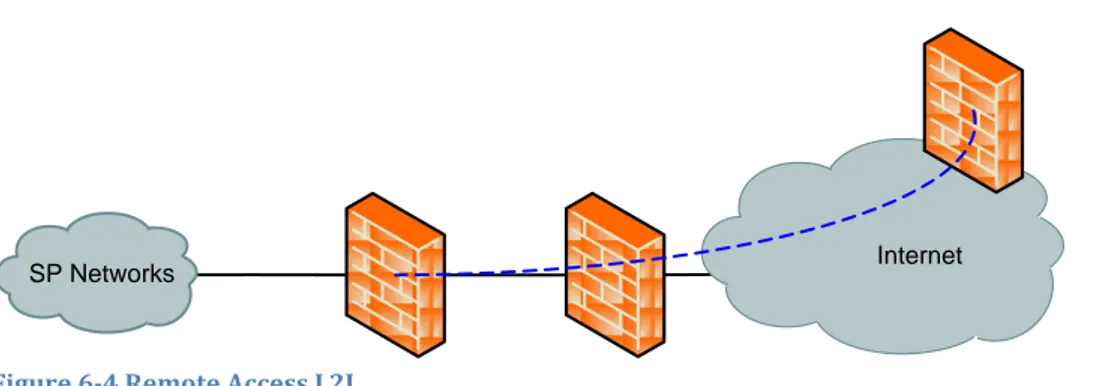
6.5.5 Remote Access L2L
Remote Access L2L consists of an IPSec encryption between a customer owned equipment and the SP’s FW. The SP assigns an IP-range for the customer to translate the IP-addresses of its CPH with. Before reaching the FW where the IPSec tunnel is terminated the traffic must pass through a FW connected to the internet. This FW will only allow IPSec to the FW terminating the IPSec tunnel. From the FW terminating the tunnel the traffic will flow to the central RA FW.
Network Classifications
The IPSec tunnel between the customer owned equipment, to the right in Figure 6-4, and the L2L FW, marked by the dotted blue line, the connection between the L2L FW and an Internet FW and the connection from the L2L FW to the SP’s Network, are all classified as Transit networks. The encrypted traffic in the IPSec tunnel originating from CPH is considered to come from an External network.
Internet SP Networks
Figure 6-4 Remote Access L2L
6.5.6 Third-party Remote Access
Subcontractors which need to access the SP’s customers will need to use a Client VPN solution [5]. The connection will be made to a FW connected to the internet. The firewall will authenticate the user’s credentials with against an authentication server. Some equipment can authenticate users directly using Microsoft Active Directory (AD) or Lightweight Directory Access Protocol (LDAP) while others need systems such as TACACS+ or Radius Server [18],[20]. Once the authentication is done, the user is given an IP-address in a separated subnet. From this subnet the user can access a terminal server from which connections to customers can be made.
Network Classifications
The Third-party VPN subnet, represented by the dotted blue line and the zone straight above the FW in Figure 6-5, is classified as an External network. When the user connects with the VPN client it extends the External network to the user. The communication for the authentication is done over an Internal network, while the communication from the Third-party FW to the SP’s Network is a Transit network.
FW
INTERNET
Third-party VPN subnet Authentication zone SP Networks Figure 6-5 Third-party VPN6.6 Overview of Remote Access
When doing an analysis of the overall structure it becomes plain that there is some equipment performing very similar tasks. Looking at each equipment type number of equipments can be minimized while still keeping the same functionality and level of security.
6.6.1 Firewalls
There is one equipment which has multiple VFWs, connected to various customer IPVPNs, one firewall connected to the SP’s own RA IPVPN and three firewalls connected to the Internet.
All the FWs cannot simply be merged into a single FW since we want to separate zones of different security classes.
They can instead be grouped by the lowest network security class they have connected. This will group the SP’s VPN FW with the VFWs used for RAWC and separately group the Internet FWs.
When choosing which FWs to implement by using VFWs it is important into take consideration what make and model is intended to be used. There are FWs which loose the VPN functionality when virtualized [23]. For the sake of generalization this will be taken into consideration when proposing a setup.
The central equipment will manage communication between all Internal, External and most Transit Networks. It is important to separate these equipments from hardware which might be vulnerable to external attacks, such as DDoS attacks [2].
Not taking fault tolerance into account four physical equipments are needed, A FW for filtering traffic to the Internal Networks, not presented in the illustration, VFW-appliance for RAWC and RAIV, Internet FW, L2L FW and Third-Party VPN FW. If, instead of managing the Third-Party VPN connections in fw05, move the functionality to the same firewall as handles the L2L VPNs then all the FW connected to the internet can also be replaced by a single VFW.
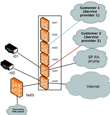
6.6.2 VPN Routers
The two routers used to terminate the VPN tunnels both have exactly the same functionality. In that aspect they could be merged into one, however for one of them this traffic originates from an External network while for the other one it originates from an Open external network. This might not be a big issue, except the RAIV solution offered to customers as a more secure solution without connections to any Open external networks. SP RA IPVPN r01 fw01 Internet r02 fw02 fw03 fw04 Third-party VPN subnet Customer 2 (Service provider 2) Customer 1 (Service provider 1)
Figure 6-6 Remote Access overview fw49 r01 Internet r02 fw50 Third-party VPN subnet SP RA IPVPN Customer 2 (Service provider 2) Customer 1 (Service provider 1) fw01 fw02 fw03 fwXX fwXY
Figure 6-7 Remote Access optimized overview 6.7 Network Zones
To reduce the risk of intrusion and to slow down intrusion attempts, the solution has been divided into separate network zones connected to the Central RA FW. The network zones with equipment which need to communicate with equipment placed in an External network will be classified as a De-Militarized Zone (DMZ). A DMZ is a “neutral” network mean to separate internal networks from external ones. What is placed in each zone is dependent of the kind of access which is needed to and from that specific equipment. Each of the zones clearly states what security class it belongs to, and what kind of equipment is meant to be placed in the zone and if it is branded as a DMZ.
Due to the sensitive nature of this information, the definitions of zones have been redacted. Internal Zone Transit Zone External Zone Open external Zone
Red
acte
d
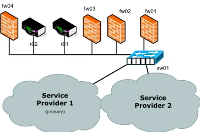
6.8 Physical Setup and Fault Tolerance
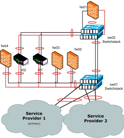
The physical setup of the IOCN could be done really simply by connecting all the equipment needed to a switch, as done in Figure 6-9. With a correct VLAN configuration to separate and distribute the networks to the right equipment the proposed solution can be realized. This setup has the drawbacks of using the same connection for both incoming and outgoing traffic, essentially cutting the bandwidth in half, more importantly it is not fault tolerant. If any of the RA FW or the RA SW should fail, the entire solution fails and if any of the other equipment fails some services will fail. By adding a switch to stack with the RA SW it and making sure all equipment is connected to it with a pair of bundled connections, using Etherchannel[26] illustrated by the red circles, will solves part of the problem. Adding an additional switch stack connected to the RA SW and moving the RA FW to it, as illustrated in Figure 6-10, the central RA FW which handles all the Internal networks can be physically separated from the Open external networks. This still leaves us with numerous equipments with no fault tolerance. fw01 fw02 Network Connection r01 r02 fw03 sw01 fw04 Service Provider 2 Service Provider 1 (primary)
fw01 fw02 r01 r02 fw03 sw01 Switchstack fw04 Service Provider 2 sw02 Switchstack Service Provider 1 (primary)
Figure 6-10 RA with switch redundancy
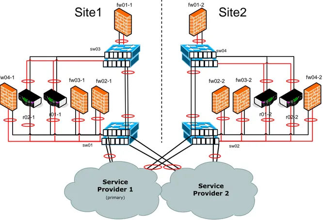
6.8.1 Geographical Fault Tolerance
To accomplish full fault tolerance duplication of the functionality of each equipment to at least one more equipment is need. This is done by doubling each equipment. If it is set up correctly this will make sure that each service or function is fault tolerant within this location, hence forth called site. The Cisco FWs use a technology called Failover, where two physical equipments have fully synchronized configurations and one is standby to the other. The routers which are used as VPN GWs will instead be configured separately to provide dual VPN tunnels to the CPR. However a disturbance to the whole site can still cause the IOCN to fail. Such disturbances can be loss of power to the whole site or cable cuts to incoming connections. The paper will discuss power more in the section 6.8.4. By setting up a second site geographically separated from the first one and placing the equipment meant to provide fault tolerance in it, a sturdy fault tolerance can be achieved as shown in Figure 6-11.
fw01-1 fw02-1 r01-1 r02-1 fw03-1 sw01 fw04-1 sw03 fw01-2 fw02-2 r01-2 r02-2 fw03-2 sw02 fw04-2 sw04 Service Provider 2 Service Provider 1 (primary)
Site1
Site2
Figure 6-11 Dual Site Remote Access
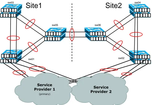
For any of the routing redundancy or failover protocols to work the equipments need have connectivity on the Data Link layer (layer 2). The connection should preferably be a high bandwidth connection so that it can be used for other traffic than redundancy communication. Many WAN service providers have services which can provide this functionality. It is however important to consider the locations of the Data Centers (DC) which is chosen, since installing new infrastructure to get access to layer 2 between DCs can be costly. If available the functionality can, for instance, be provided by fiber optic connection between the sites. However this can be an expensive solution. Instead service providers can offer layer 2 connectivity by providing a wavelength in the optical connection.
With such services the DCs can be connected with a layer 2 connection and allow the use of cross site fault tolerance. If there is an abundance of interfaces on the site it is recommended to connect the switches fully meshed. As shown in Figure 6-12, the proposed solution will use 2 connections bundles by Etherchannel between each switch.
sw01 sw03 sw02 sw04 Service Provider 2 Service Provider 1 (primary)
Site2
sw05 sw06Site1
Figure 6-12 Remote Access Layer 2 Connections 6.8.2 Gateway Redundancy
The paired FW running failover will act as a single unit, where the standby waits idle, unless they are set to run in High Availability (HA) mode. When running HA the states of all sessions will be synchronized to the standby FW for seamless takeover should the primary FW fail.
None-FW equipment runs HSRP as a means of redundancy. Each unit, router or other layer 3 equipment, is given a static address. Paired units are additionally assigned a virtual address which can move back and forth between the devices. As mentioned earlier, for this to work the interfaces need to have layer 2 connectivity to be able to determine the state of equipment and port it is paired with.
In Figure 6-13, the primary FW will always have the IP-address finishing with “.4”, while the WAN service provider routers will each have an individual address “.2” and “.3” while sharing the address “.1”.
.1
IPVPN
WAN SP Router
Site 1 WAN SP Router
Site 1 FAILOVER HSRP & Data sw02 sw01 .2 .3 FW Cluster .4 .5
Figure 6-13 Failover and HSRP
6.8.3 Service Provider Fault Tolerance
It is important to make sure that services asked for of the service provider are fault tolerant. There are many variations and levels of fault tolerance available. A
recommendation is to make sure the fault tolerance extends to cabling for redundant WAN connections being physically separated and not just redundant cables in the same pipes or redundant equipment on site.
6.8.4 Fault Tolerant Power supply
It is common for equipment to fail because of power failure. It can be the equipments power supply unit (PSU) which fails or a failing fuse. Making sure that all equipment has two PSUs each one of them connected to a separate fuse can minimize unnecessary power related faults. To ensure that the site can keep going even through larger scale power outages the one of the PSUs should be connected to a uninterruptible power supply (UPS) backup up by a diesel generator. Most DCs provide this kind of service and most providers’ backbone equipment are protected by UPS, ensuring that uptime of the service.
6.9 Security and Traceability
SPs are often accountable toward their customers and need to be able to explain course events when incidents occur. This together with regulatory demands from governmental organizations in turn puts a responsibility on the SP to minimize the risks of incidents occurring. Incidents can be unauthorized access to systems, system failures or user mistakes. To protect against unauthorized accesses communication passing through a SP owned FW to any system, customer placed or internal, can be controlled on user basis. Using functionalities like Cisco’s Identity Firewall (IDFW) the administrator can design FW rules based on user and/or group level.
As a complement to enforcing rules logging can help follow up course of event when an unforeseen incident has occurred. When setting up an infrastructure like a IOCN every equipment should be configured to send log events to a log receiver. There is a large variety of products for logging, everything from syslog on Linux to advanced logging systems like ArcSight.
6.10 Substituting brand specific functions
The presented solution can easily be adapted to use equipment from other vendors simply by replacing some of the technologies and protocols used. Failover and HSRP can with Checkpoint be replaced by using Clustering and Virtual Router Routing Protocol (VRRP) [27]. For user based access rules Cisco’s Identity Firewall (IDFW) [29] can be replaced with Checkpoint’s Identity Awareness Software (IAS) [30] and other vendors have their own equivalent functionalities. Etherchannel can be replaced by Link Aggregation Control Protocol (LACP) [31] and on checkpoint firewalls bonding can be used.
7. Discussion
Early in the paper the problem of lack of research on core networks for inter-organizational communication was presented. I have contributed to this lack of research by evaluating an existing IOCN, analyzing the flaws and suggesting a basic design for a stable and secure solution.
Using the existing system and the needs of the SP as a starting point has greatly influenced the result. The most notable evidence of this is the choice of equipment using proprietary technologies, although suggestions for how the solution could be more
stability of the network infrastructure has led to not taking other factors, like bandwidth optimization and host security, into account.
Much of the result, such as achieving fault tolerance and how segmentation of the networks can been done to increase security, is general and could be applied to any core network with focus on delivering a service.
The proposed solution will enable the company to deliver services with a need for better availability to customers, minimizing the risks of its technicians and systems not being able to reach customer equipment. The drawback is that the initial investment could be higher due to increased equipment, but can instead support more customer and more demanding customer, which in turn can generate more income for the company.
Since the start of the paper a lot of changes have been made to the original solution and parts of the proposed solution has been implemented to increase fault tolerance and security. The needs of the SP have also evolved with time and added new requirements on the solution, which this thesis has not addressed or taken into consideration.
7.1 Related work
The solution Huaqi Chen presented in his paper [10] does not consider sites which should not be able to communicate with each other. On the other hand his work is focused on internal communication within a company whereas this thesis which deals with IOCN focuses one communication between different companies. Therefore it is important to take into consideration that the different sites in the network are separate customers and should not be able to communicate with any other site than the SP’s central sites.
Wang et al.’s comprehensive study on DCN architectures and network protocols gives a good overview of the state of the art techniques used to ensure high performance and fault tolerance in data center [6]. These DCN architectures however focus on networks with a large number of hosts and constantly growing environments. The IOCN is a relatively static environment where the number of host is not dependent on the number of customer.
8. Conclusions
The aim of the thesis has been to design a secure and fault tolerance network
architecture for an inter-organizational communication network. For service providers such an infrastructure is vital so as to be able to deliver services to customers with a high demand on security, availability and flexibility. This is done by analyzing an existing IOCN with the focus of identifying the flaws in its security and fault tolerance and
proposing a new solution.
The new solution is a geographically distributed infrastructure where not only equipment has been mirrored, but also functionality with the help of redundancy protocols. The security has been improved by segmenting the networks into clearly defined zones and general rules for interaction between zones.
8.1 Future Work
This paper has focused on the central infrastructure of an IOCN. Future work could look at security and flexibility of the RA IPVPN and RA Internet Connect solutions. Considerations can be made for replacing IPSec and GRE with DMVPN and what consequences and benefits it might have on the services. Other future work can
research logging, what should be logged, how and how long it should be stored and how it can and should be used.
References
[1] Rabinovitch, E., "Maintaining a secure networking infrastructure," Information Technology: Research and Education, 2003. Proceedings. ITRE2003.
International Conference on, pp.587-589, Aug 2003. Available: IEEEXplore http://ieeexplore.ieee.org/ doi: 10.1109/ITRE.2003.1270687 [Fetched: 6 May, 2015]
[2] Rufi. AW, Network Security 1 and 2 Companion, Indianapolis, Ind.: Cisco Press, c2007, p. 1-49
[3] Sophos, 'Security Threat Report 2013', 2013.
[4] European Commission Information Society and Media Directorate-General, 'STATISTICAL DATA ON NETWORK SECURITY', Bruxelles, 2007.
[5] Jaha, A.A.; Ben-Shatwan, F.; Ashibani, M., "Proper Virtual Private Network (VPN) Solution," Next Generation Mobile Applications, Services and Technologies, 2008. NGMAST '08. The Second International Conference, pp.309, 314, 16-19 Sept. 2008. Available: IEEEXplore http://ieeexplore.ieee.org/
doi:10.1109/NGMAST.2008.18
[6] Ting Wang; Zhiyang Su; Yu Xia; Hamdi, M., "Rethinking the Data Center
Networking: Architecture, Network Protocols, and Resource Sharing," Access, IEEE , vol.2, no., pp.1481,1496, Dec 2014 doi: 10.1109/ACCESS.2014.2383439 [7] Dawei Wang; Xian-He Sun; Nongda Hu; Ninghui Sun "EthSpeeder: A
High-performance Scalable Fault-Tolerant Ethernet Network Architecture for Data Center," Networking, Architecture and Storage (NAS), 2011 6th IEEE
International Conference on, pp.355-363, Jul 2011. Available: doi: 10.1109/NAS.2011.44
[8] Wang Huiqiang; Yin Zhenliang; Wang Dao "A parallel and fault-tolerant LAN with dual communication subnetworks," Parallel Algorithms/Architecture Synthesis, 1997. Proceedings., Second Aizu International Symposium, pp.340-346, Mar 1997. Available: doi: 10.1109/AISPAS.1997.581688
[9] Richardson, P.; Sieh, L. "FT-LAN, a fault tolerant local area network architecture for mobile mission critical systems," Computer Communications and Networks, 2000. Proceedings. Ninth International Conference, pp.170-175. Oct 2000, Available: doi: 10.1109/ICCCN.2000.885487
[10] Chen, H. "Design and implementation of secure enterprise network based on DMVPN," Business Management and Electronic Information (BMEI), 2011 International Conference, vol.1, pp.506-511, May 2011. Available: doi: 10.1109/ICBMEI.2011.5916984
[11] Dong Lin; Yang Liu; Hamdi, M.; Muppala, J. (2012, Jun). "Hyper-BCube: A scalable data center network," Communications (ICC), 2012 IEEE International
Conference, pp.2918- 2923, Jun 2012. Available: doi: 10.1109/ICC.2012.6363759 [12] Smith, R.N.; Bhattacharya, S. "Firewall placement in a large network topology,"
Distributed Computing Systems, 1997, Proceedings of the Sixth IEEE Computer Society Workshop on Future Trends, pp.40-45, Oct 1997. Available: doi:
10.1109/FTDCS.1997.644701
[13] Kent, S., Seo, K. Security Architecture for the Internet Protocol [Online], Dec 2005. Available: http://www.rfc-base.org/txt/rfc-4301.txt
[14] D. Farinacci, D., Li, T., Hanks, S., Meyer, D., Traina, P. Generic Routing Encapsulation (GRE) [Online], Mar 2000. Available:
[15] Icann.org, “Remaining IPv4 Addresses to be Redistributed to Regional Internet Registries | Address Redistribution Signals that IPv4 is Nearing Total Exhaustion – ICANN”, 2014. [Online]. Available:
https://www.icann.org/news/announcement-2-2014-05-20-en. [Accessed: 10 May, 2015].
[16] Smith, M.; Hunt, R., "Network security using NAT and NAPT (2002)." Networks, 2002. ICON 2002. 10th IEEE International Conference, pp.355-360, 2002. Available: doi: 10.1109/ICON.2002.1033337
[17] McGee, A.R.; Chandrashekhar, U.; Richman, S.H., (2004, Jun) "Using ITU-T X.805 for comprehensive network security assessment and planning,"
Telecommunications Network Strategy and Planning Symposium. NETWORKS 2004, 11th International, pp.273-278, Jun 2004. Available:
doi:10.1109/NETWKS.2004.1341856
[18] IEEE Standard for Information Technology: Hardcopy Device and System Security, IEEE Std 2600-2008, pp.1-177, Jun 2008. Available:
doi:10.1109/IEEESTD.2008.4556653
[19] McAfee Labs, 'McAfee Labs Threats Report', 2015.
[20] Finseth, C. An Access Control Protocol, Sometimes Called TACACS [Online], Jul 1993. Available: https://tools.ietf.org/html/rfc1492
[21] Mohd Shaid, S.Z.; Maarof, M.A., (2014, Aug). "Malware behavior image for
malware variant identification," Biometrics and Security Technologies (ISBAST), 2014 International Symposium pp.238-243, 26-27, 2014 Aug. Available: doi: 10.1109/ISBAST.2014.7013128
[22] Hsien-De Huang; Chang-Shing Lee; Hung-Yu Kao; Yi-Lang Tsai; Chang, Jee-Gong, (2011, Apr) "Malware behavioral analysis system: TWMAN," Intelligent Agent (IA), 2011 IEEE Symposium on , vol., no., pp.1-8. Available: doi:
10.1109/IA.2011.5953604
[23] Cisco, 'Cisco Security Appliance Command Line Configuration Guide, Version 8.0 - Enabling Multiple Context Mode [Cisco ASA 5500-X Series Next-Generation Firewalls]', 2015. [Online]. Available:
http://www.cisco.com/c/en/us/td/docs/security/asa/asa80/configuration/gui de/conf_gd/contexts.html. [Accessed: 20 May, 2015].
[24] Sc1.checkpoint.com, 'VSX Architecture and Concepts', 2015. [Online]. Available: https://sc1.checkpoint.com/documents/R76/CP_R76_VSX_AdminGuide/5998.ht m. [Accessed: 20- May- 2015].
[25] Peng, W., Zhou, Y., Wang, C., and Yang, Y. (2009, Nov) "Research on IPSec-based NAT-PT transition mechanism," Network Infrastructure and Digital Content, 2009. IC-NIDC 2009. IEEE International Conference, pp.222-226, Nov 2009. Available: doi: 10.1109/ICNIDC.2009.5360823
[26] Cisco, 'Catalyst 3550 Multilayer Switch Software Configuration Guide,
12.1(13)EA1 - Configuring EtherChannels [Cisco Catalyst 3550 Series Switches]', 2015. [Online]. Available:
http://www.cisco.com/c/en/us/td/docs/switches/lan/catalyst3550/software/r elease/12-1_13_ea1/configuration/guide/3550scg/swethchl.html. [Accessed: 20 May, 2015].
[27] Sejun Song; Baek Young Choi. "Scalable fault-tolerant network design for Ethernet-based wide area process control network systems," Emerging Technologies and Factory Automation, 2001. Proceedings. 2001 8th IEEE
International Conference, vol.1, pp.315-323, Oct 2001. Available: doi: 10.1109/ETFA.2001.996384
[28] Yadong Li; Wenqiang Cui; Danlan Li; Rui Zhang. "Research based on OSI model," Communication Software and Networks (ICCSN), 2011 IEEE 3rd International Conference, pp.554, 557, May 2011. Available: doi:
10.1109/ICCSN.2011.6014631
[29] Cisco, 'CLI Book 1: Cisco ASA Series General Operations CLI Configuration Guide, 9.3 - Identity Firewall [Cisco ASA 5500-X Series Next-Generation Firewalls]', 2015. [Online]. Available:
http://www.cisco.com/c/en/us/td/docs/security/asa/asa93/configuration/gen eral/asa-general-cli/aaa-idfw.html. [Accessed: 20 May, 2015].
[30] Adding users to the security policy (2013). [Online]. Available:
https://sc1.checkpoint.com/documents/R76/CP_R76_Firewall_WebAdmin/9270 5.htm
[31] IEEE Standard for Local and metropolitan area networks -- Link Aggregation, (Dec, 2014)" IEEE Std 802.1AX-2014 (Revision of IEEE Std 802.1AX-2008)”, pp.1-344, Dec 2014. Available: doi:10.1109/IEEESTD.2014.7055197
Abbreviations
AD – Active Directory
CLI – Command-Line Interface CPH – Customer Placed Host CPR – Customer Placed Router DC – Data Center
DCI – Data Center Internconnect DCN – Data Center Network
DDoS – Distributed Denial of Service DGW – Default Gateway
DMVPN – Dynamic Multipoint Virtual Private Network DMZ – De-Militarized Zone
FT – Fault Tolerance FW – Firewall
GRE - Generic Routing Encapsulation GW – Gateway
HA – High Availability
HSRP – Hot Standby Routing Protocol IAS – Identity Awareness Software IDFW – Identity Firewall
IOC – Inter-Organization Communication
IOCN – Inter-Organization Communication Network IP – Internet Protocol
IPSec – IP Security
IPVPN – VPN over IP using MPLS IPv4 – Internet Protocol version 4
ISDN – Integrated Services Digital Network KC – Key Customer
L2L – LAN-To-LAN
LACP – Link Aggregation Control Protocol LAN- Local Area Network
LDAP – Lightweight Directory Access Protocol MPLS – Multiprotocol Label Switching
NAPT – Network Address Port Translation NAT – Network Address Translation
NAT-PT – Network Address Translation – Port Translation OSI – Open System Interconnection
PSU – Power Supply Unit RA – Remote Access
RAIC – Remote Access Internet Connect RAISDN – Remote Access ISDN
RAIV – Remote Access IPVPN RAL2L – Remote Access L2L
RAVG – Remote Access VPN Gateway RAWC – Remote Access WAN Connect SP – Service Provider
SPOF – Single Point Of Failure SW – Switch
UPS – Uninterruptible Power Supply VFW – Virtual Firewall
VLAN – Virtual Local Area Network VPN – Virtual Private Network
VRRP – Virtual Router Redundancy Protocol WAN – Wide Area Network