Evaluation of SKB/Posiva’s report
on the horizontal alternative of
the KBS-3 method
Authors:2009:35
Michael J. Apted David G. Bennet Timo Saario David Savage Peter Segle Göran SällforsTitle: Evaluation of SKB/Posiva’s report on the horizontal alternative of the KBS-3 method Report number: 2009:35
Author/Authors: LMichael J. Apted, David G. Bennet, Timo Saario, David Savage, Peter Segle and Göran Sällfors
Date: October 2009
This report concerns a study which has been conducted for the Swedish Radiation Safety Authority, SSM. The conclusions and viewpoints pre-sented in the report are those of the author/authors and do not neces-sarily coincide with those of the SSM.
Background
The KBS-3 method, based on multiple barriers, is the proposed spent fuel disposal method both in Sweden and Finland. The method has two design alternatives: the vertical (KBS-3V) and the horizontal (KBS-3H). SKB and Posiva have conducted a joint research, development and de-monstration (RD&D) programme in 2002-2007 with the overall aim of establishing whether the KBS-3H represents a feasible alternative to the reference alternative KBS-3V. The objectives have been to demonstrate that the horizontal deposition alternative is technically feasible and that it fulfils the same long-term safety requirement as the KBS-3V.
Swedish Radiation Safety Authority (SSM) considers that it is a proper time to evaluate the work carried by SKB and Posiva when this period of joint research is ended and a relatively complete set of reporting is avai-lable. SSM therefore required its external expert group BRITE (the Barrier Review, Integration, Tracking and Evaluation) to evaluate the reporting. Objectives of the project
The aims of the evaluation are to investigate the differences between the horizontal and vertical design alternatives with respect to:
• Completeness: has SKB/Posiva identified the full set of key topics, and if not, what additional specific key topics should be evaluated; • Depth-of-treatment: has SKB/Posiva analysed the key topics in
sufficient depth, and if not, on what specific aspects in more de-tailed consideration required;
• Status of information: has SKB/ Posiva provided enough informa-tion on the current status of knowledge and uncertainties that impact the understanding of each key topic, and if not, what further information should be cited;
• Feasibility and practicality: for key issues related to the fabrica-tion and emplacement of the two different designs, has SKB/ Posiva provided sufficient demonstration (or detailed plans for demonstration) of engineering feasibility and practicability to al-low confident evaluations to be made regarding the likelihood of resolving these issues;
• Impact on long-term safety: for key issues that are resolved, would the differences in the design have significant impact on the long-term safety;
• Resolution strategy: for key issues that are not yet resolved, has SKB/Posiva identified a feasible work programme and schedule for resolving each issue. Will these key issues have possible sig-nificant impact on the long-term safety if possibly be resolved? Results
The initial reporting on the KBS-3H conceptual design made by SKB and Posiva presents only preliminary information and analyses, and considerable uncertainties remain that limit the ability to fully assess the feasibility and long-term safety of the KBS-3H design concept. Only preliminary comparisons can be made between the KBS-3H and KBS-3V design alternatives in this report.
The preliminary comparisons indicate that there are processes and de-sign specifications that are rather different in the two dede-sign alternatives and they may have important impact on the long-term safety. Further RD&D work is needed for SKB and Posiva to fully resolve the issues.
Content
1. Purpose...3
2. Assessment of the feasibility of repository and EBS construction and implementation ...6
2.1 Issue description ...6
2.2 SKB/Posiva’s perspective...6
2.3 BRITE comments...6
3. Rock spalling and effects...8
3.1 Issue description ...8
3.2 SKB/Posiva’s perspective...8
3.3 BRITE comments...9
4. Water inflow to the deposition drifts...10
4.1 Issue description ...10
4.2 SKB/Posiva’s perspective...10
4.3 BRITE comments...13
5. Piping and erosion of the bentonite buffer...15
5.1 Issue description ...15
5.2 SKB/Posiva’s perspective...15
5.3 BRITE comments...17
6. Sealing of deposition drifts...19
6.1 Issue description ...19 6.2 SKB/Posiva’s perspective...19 6.3 BRITE comments...19 6.3.1 Distance blocks...19 6.3.2 Filling blocks ...20 6.3.3 Compartment plugs ...21
6.3.4 Drift end plug and drip shields ...21
6.3.5 Deposition niche ...22
7. Corrosion of steel components external to the canister ...23
7.1 Issue description ...23
7.2 SKB/Posiva’s perspective...23
7.3 BRITE comments...25
8. Effects of steel corrosion on bentonite and radionuclide transport ....27
8.1 Issue description ...27
8.2 SKB/Posiva’s perspective...30
8.3 BRITE comments...31
9. Impact of gas from the corrosion of steel components external to the canister, gas flow and implications...35
9.1 Issue description ...35
9.2 SKB/Posiva’s perspective...35
9.3 BRITE comments...36
10. Impact of leachates from cementitious components ...38
10.1 Issue description...38
10.2 SKB/Posiva’s perspective...38
10.3 BRITE comments...39
11. Processes within horizontal failed canisters...42
11.1 Issue description...42
11.2 SKB/Posiva’s perspective...42
11.3 BRITE comments...43
12. Implications of the horizontal arrangement with respect to potential for earthquake shear...45
12.2 SKB/Posiva’s perspective...46 12.3 BRITE comments...46
1. Purpose
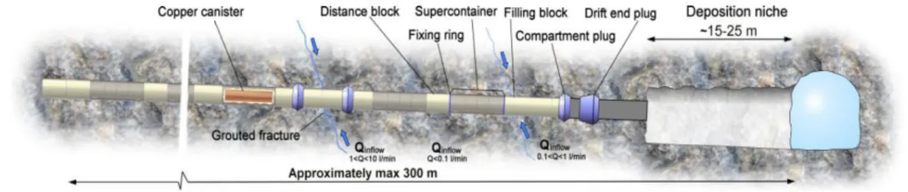
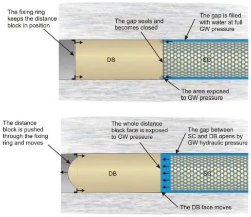
The BRITE group supports the Strålsäkerhetsmyndigheten (SSM, the Swed-ish Radiation Safety Authority) in providing independent evaluations of topics and issues associated with the engineered barrier system (EBS) of the planned deep geological repository for the disposal of Swedish spent nuclear fuel (SNF). As part of this independent support to SSM, the BRITE group was requested to evaluate the recent series of reports produced by SKB in Sweden and Posiva in Finland on the so-called “KBS-3H” concept design. In the KBS-3H concept, copper canisters loaded with SNF are encased in a compacted bentonite buffer with an outer supporting supercontainer com-posed of a mild steel basket, and the entire supercontainer is emplaced hori-zontally in long emplacement drifts (Figure 1-1).
Figure 1-1 The Basic Design for KBS-3H (SKB, 2008, TR-08-03).
The SKB/Posiva reports cover a wide range of topics, including: • design variants under consideration,
• field demonstration of emplacement techniques,
• laboratory tests examining behavior of EBS components under simulated repository conditions,
• computer-aided analysis of EBS behavior under changes in re-pository conditions,
• scoping analyses using performance assessment models to esti-mate impacts on long-term radionuclide release rates for various speculative ‘what if?” scenarios,
• identification of remaining uncertainties in assessing the feasi-bility and safety of the KBS-3H concept, and
• plans to further address and resolve these remaining uncertain-ties.
The SKB/Posiva reports also present and contrast differences between the KBS-3H conceptual design and the reference KBS-3V design in which
es-sentially the same EBS components of bentonite buffer, copper canister and spent nuclear fuel (SNF) are emplaced vertically, but without a steel basket. The aims of BRITE’s evaluation of the KBS-3H reports have been to inves-tigate the information presented by SKB and Posiva on the KBS-3H concep-tual design with respect to:
• completeness: have SKB/Posiva identified the full set of issues that need to be considered when assessing the feasibility and safety of the KBS-3H design, and if not, what additional specific key topics should be evaluated?
• impacts: what are the impacts of these issues on feasibility and long-term safety.
• resolution strategy: for key issues that are not yet resolved, have SKB/Posiva identified an appropriate, feasible work programme and schedule for resolving each issue?
• differences between the KBS-3H and the KBS-3V designs: do these differences have significant impact on operational feasibil-ity and/ or long-term safety of the repository?
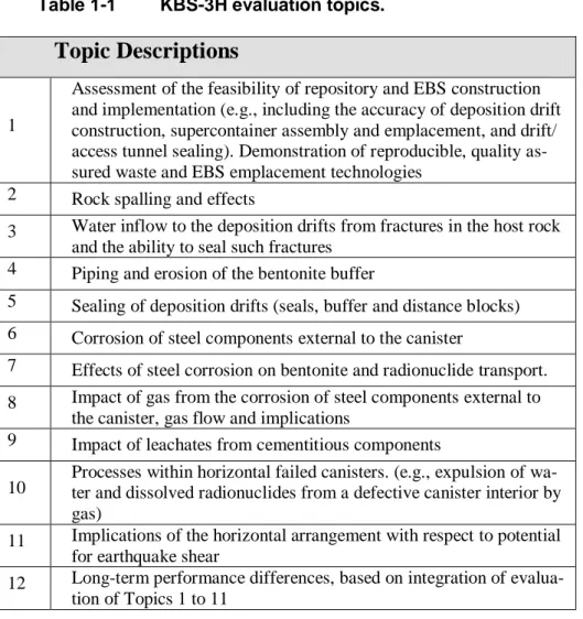
The BRITE group was requested to address certain key topics in their evaluation of the KBS-3H concept and supporting reports (Table 1-1). The following sections of the report contain the collected evaluations by the BRITE group on the topics identified in Table 1-1. A final summary section presents a collective evaluation of the status and remaining key areas of con-cern with respect to demonstrating the feasibility and long-term safety of the KBS-3H conceptual design.
Table 1-1 KBS-3H evaluation topics.
Topic Descriptions
1
Assessment of the feasibility of repository and EBS construction and implementation (e.g., including the accuracy of deposition drift construction, supercontainer assembly and emplacement, and drift/ access tunnel sealing). Demonstration of reproducible, quality as-sured waste and EBS emplacement technologies
2 Rock spalling and effects
3 Water inflow to the deposition drifts from fractures in the host rock and the ability to seal such fractures
4 Piping and erosion of the bentonite buffer
5 Sealing of deposition drifts (seals, buffer and distance blocks) 6 Corrosion of steel components external to the canister
7 Effects of steel corrosion on bentonite and radionuclide transport. 8 Impact of gas from the corrosion of steel components external to
the canister, gas flow and implications
9 Impact of leachates from cementitious components
10 Processes within horizontal failed canisters. (e.g., expulsion of wa-ter and dissolved radionuclides from a defective canister interior by gas)
11 Implications of the horizontal arrangement with respect to potential for earthquake shear
12 Long-term performance differences, based on integration of evalua-tion of Topics 1 to 11
2. Assessment of the
feasi-bility of repository and EBS
construction and
implemen-tation
2.1 Issue description
Many of the safety issues identified by SKB/Posiva are based on the as-sumption that a KBS-3H repository can be constructed and operated safely. Conversely, many of the other safety issues considered in later sections of this report could adversely impact the feasibility of constructing and safely operating a KBS-3H repository, for example inflow of groundwater and potential rock spalling. As described in Topic 3 on control of inflow groundwater, for example, it is already evident that the initial Basic Design (BD) is probably not suitable, and that alternative design variants are under active evaluation.
2.2 SKB/Posiva’s perspective
SKB/Posiva acknowledge that there remain a number of design issues out-standing that will have to be addressed in future studies. Should these studies result in significant changes to the Basic Design (BD) and greater reliance on either the Drainage, Artificial Watering and air Evacuation (DAWE) or Semi-Tight Compartment (STC) variant designs, then these changes could have implications for the key safety issues considered in the present evalua-tion. Specific uncertainties identified by SKB/Posiva regarding design, op-erational and emplacement developments are summarized in Section 4.7, SKB, 2008.
2.3 BRITE comments
Issues regarding operational and construction feasibility are among the most difficult for SKB/Posiva to convincingly show resolution because they should involve large-scale and reproducible demonstrations of technology under in situ conditions and with actual EBS materials. Furthermore, appli-cation of bounding analyses (see Smith et al., 2008) to resolve an issue are generally not suitable for design, construction and operational questions because relevant and defensible “bounds” of parameters often cannot be identified without demonstration at relevant scales and working conditions.
For these reasons, SKB and Posiva have identified a further set of studies on the KBS-3H conceptual design through at least 2012 (SKB, 2008). While it is premature to judge the viability of the KBS-3H concept at this preliminary stage, it is important to note that SKB/Posiva have shown excellent progress in underground demonstrations of the prototype KBS-3H emplacement tech-nology at full scale. Based on considerable underground demonstrations and laboratory testing by SKB/Posiva, there are no indications of any “show-stoppers” that would imply the KBS-3H concept is not viable. However, tests and trials have not been completed for all of the proposed EBS compo-nents, and further work is certainly required.
SKB/Posiva intend to carry out a number of further studies addressing sign issues, including: 1) avoidance of distance block displacement and de-formations; 2) avoidance or limitation of thermally induced rock spalling; 3) alternative supercontainer materials; and 4) layout to avoid potentially prob-lematic fractures (see Smith et al., 2008). Certain design features, such as the nature of materials used in filling blocks, and operational features, such as the use of mega-packers to inject grouts into fractures, also appear to be in a state of continuing development. Details regarding future studies in these areas are not provided in the reviewed documentation, so it is not possible to evaluate the likelihood or timeliness of possible successful resolution to these issues.
There are certain key operational steps that are of particular interest at this time. First, the fabrication, handling, transportation and emplacement of the assembled supercontainer into the underground emplacement drift are yet to be fully integrated and demonstrated. Successful demonstrations of emplac-ing equivalent weight cement supercontainers need to be extended to em-placement of actual bentonite-based supercontainers, which could prove to be less durable and inert (with respect to hydration and expansion) compared to the previous cement proxy. Second, the megapacker with silica sol gel has been shown to successfully seal high-flow fractures (Topic 3). The du-rability of this sealing compared to the necessary timeframe for overall em-placement of multiple supercontainers in a 300-m long drift, however, has not yet been confirmed. Third, the potential for spalling (Topic 2), especially in the relatively dry and high stress host rock at Forsmark, and potential design/operational countermeasures (induced saturation of buffer) remain to be reliably demonstrated. Lastly, additional design concerns, possibly af-fecting construction and operations, are articulated in other sections of this report.
In summary, the various KBS-3H reports present a reasonably complete documentation of the progress-to-date for the KBS-3H conceptual design, and associated issues. Inability to eventually resolve remaining aspects of construction, operations and emplacement of supercontainers would proba-bly prevent the viability of the KBS-3H design concept. As noted above, “bounding analyses” are unlikely to be suitable for resolving outstanding construction, operations and emplacement issues; only eventual full-scale, reproducible demonstration under in situ conditions can fulfil the necessary requirements for confidence in the KBS-3H design concept.
3.
Rock spalling and
ef-fects
3.1 Issue description
If the local stress field in a deposition hole diverges from the stress field assumed based on regional measurements, excavation-induced rock spalling may occur and the deposition tunnel may be damaged and lose its circular shape. Thermally induced stresses from emplaced supercontainers could further exacerbate stress anisotropy in the rock, leading to enhanced spalling. Furthermore, where the host rocks are relatively “dry”, the delay in resatura-tion of the buffer would act to prevent the buffer from swelling, and this, in turn, would mean that the buffer would not act to prevent further spalling of the rock. This could possibly cause enhanced spalling, a greater depth of spalling, and circumferential extension in the borehole wall.
The potential for rock spalling has several implications:
• First, spalling may adversely impact the feasibility of emplace-ment of supercontainers over the targeted 300-m length of a deposition drift.
• Second, in wetter host rock regions, a high groundwater pressure difference could develop rapidly in the void volume created by the rock spall, resulting in enhanced piping and erosion of the bentonite, and a reduction in swelling pressure that might lead to enhanced thermally-induced spalling and generally adverse con-ditions.
• Third, spalling could result in changed groundwater-flow condi-tions at the buffer - host rock interface. Enhanced flow at this boundary could affect radionuclide transport rates.
3.2 SKB/Posiva’s perspective
Smith et al. (2008, Section 7, pages 97-98) approaches the potential impacts of thermal spalling of rock by setting up a sensitivity case, PD-SPALL, where a thermally induced spalling region is treated as a highly conductive mixing tank boundary condition to an initially failed canister. PD-SPALL assumes that spalling occurs in a region of relatively hydraulically tight rock, with groundwater flow lower than that assumed in cases assuming mechani-cal disruption by other factors such as effects of steel corrosion products. SKB/Posiva do acknowledge that thermally induced spalling could occur in less tight sections, although calculations with higher groundwater flow were not made. The results of PD-SPALL show a slight decrease in peak release rate compared to the base case (see Figure 9-10, Smith et al., 2008).
3.3 BRITE comments
Scoping calculations in Smith et al. (2008) only address one of the several possible performance and feasibility impacts of rock spalling. The impact on operational feasibility (i.e., emplacing supercontainers along 300-m lengths of the emplacement drift that might be experiencing spalling), and the poten-tial for enhanced piping and erosion during both the operational and the far-future glacial periods are not addressed directly.
In order to avoid/minimize spalling of the KBS-3H emplacement drifts, SKB/Posiva would have to attempt orient the deposition drifts parallel with the direction of the maximum horizontal principal stress, which may vary spatially. If deposition drifts in the KBS-3H concept are oriented incorrectly with respect to the maximum principal stress, major spalling of the deposi-tion holes would likely result. Furthermore, the most adverse situadeposi-tion of spalling would likely develop in case of dry sections of deposition drifts where there is no early counter-pressure arising from the resaturation and swelling of the buffer. It is noted that the recently selected Forsmark site is believed to be characterized by dry conditions and possibly by relatively high anisotropic stresses.
If spalling occurs before supercontainer emplacement and this is observed or detected, SKB/Posiva have then to decide either to abandon the deposition hole and fill the opening with buffer material, or to develop a technique to install the supercontainer and fill the gap from the spalling with buffer mate-rial. If the spalling causes a volume loss, it must not be so large that it leads to an unacceptable loss of density of the bentonite due to swelling and filling of the void. No method for possibly compensating the volume loss has been proposed or discussed, nor has a critical volume loss been determined for when the standard procedure is insufficient.
There are some other difficulties that might arise, depending on whether BD, DAWE or STC design variants will be used. For BD the tolerances are small and even minor events of spalling might jeopardize the placing (or retrieval) of the supercontainer if the spalling is not dealt with.
The gap between the supercontainer and the rock wall for the DAWE case is large enough so that spalling might not necessary jeopardize the transport of the supercontainer. However, if spalling occurs before the pipes for the arti-ficial wetting are withdrawn, such spalling might severely complicate the procedure of withdrawal.
In conclusion, spalling appears to be a potentially significant issue that has not yet been fully assessed, and for which engineering solutions are still under development.
4.
Water inflow to the
deposition drifts
4.1 Issue description
Water inflows to the repository drifts may, amongst other things, affect: • The feasibility of waste emplacement.
• The locations that can be used for waste emplacement. • The requirements for flow controls and sealing of fractures. • The rate of bentonite hydration and swelling.
• Piping and erosion (see Topic 4), and the generation and trans-port of colloids.
• The transport of dissolved substances to the supercontainer and the canister, and, therefore, their corrosion rates and the rate of gas production (see Topic 5).
• The transport of radionuclides.
Water inflows depend on rock hydraulic conductivities and, in tighter drift sections, on gas pressures possibly developed by corrosion of engineered barrier system components.
There may be significant spatial heterogeneity along each drift and between drifts.
4.2 SKB/Posiva’s perspective
SKB/Posiva’s approach is to manage water inflows by designing and im-plementing a suitable engineered barrier system.
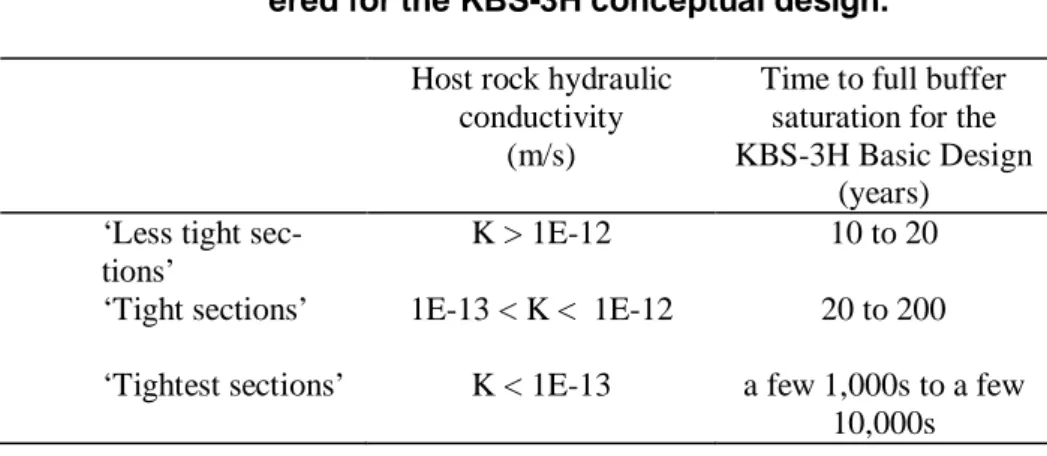
In their assessments SKB/Posiva distinguish three host rock water-inflow regimes (Table 4-1):
Table 4-1 Three Host-rock water-inflow regimes consid-ered for the KBS-3H conceptual design.
Host rock hydraulic conductivity
(m/s)
Time to full buffer saturation for the KBS-3H Basic Design
(years) ‘Less tight
sec-tions’
K > 1E-12 10 to 20 ‘Tight sections’ 1E-13 < K < 1E-12 20 to 200 ‘Tightest sections’ K < 1E-13 a few 1,000s to a few
10,000s
Although SKB/Posiva note that distinguishing between the Tight and Tight-est sections in the real repository might be difficult in practice.
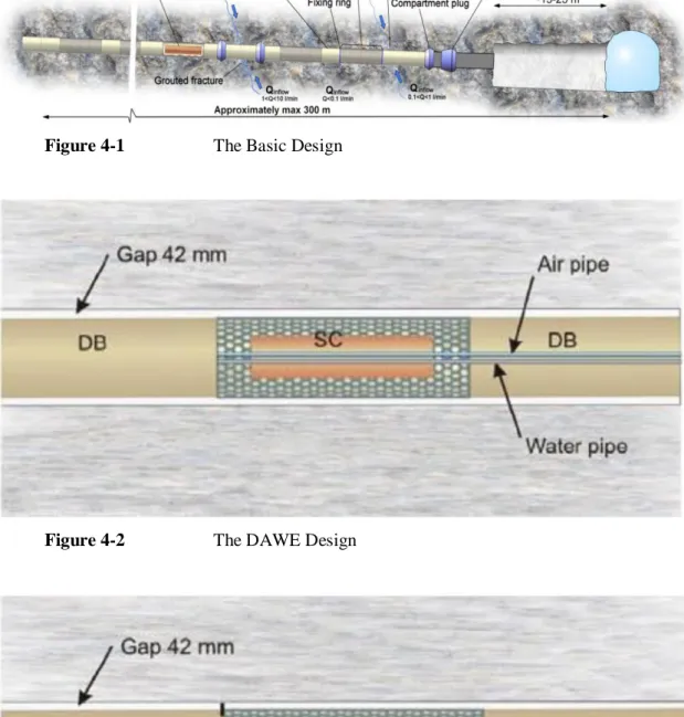
SKB/Posiva are considering three variants of the KBS-3H design, each with differing arrangements for the management of water inflows:
• The Basic Design (Figure 4-1).
• The DAWE (Drainage, Artificial Watering and air Evacuation) Design (Figure 4-2).
• The STC (Semi-Tight Compartment) Design (Figure 4-3). Key features of the Basic Design include:
• Pre-excavation and post-excavation grouting using silica sol or low-pH cements in order to seal fractures in the host rock and reduce water inflows. SKB/Posiva have developed and demon-strated use of a ‘Mega-Packer’ tool for the sealing of fractures that intersect the repository drifts. However, because grout penetration and fracture sealing cannot be directly measured during grouting, and the long-term performance of the grouts and fracture seals are uncertain, they are not relied on for long-term performance.
• Compartment plugs will be used to seal off drift sections where water inflows are still >1 l/min over a 10 m length of drift after grouting. The design of the compartment plugs is still in pro-gress and demonstration tests are planned at the Äspö under-ground research laboratory.
• Filling blocks will be used for other unsuitable sections of rock that are not sealed with compartment plugs. Filling blocks will be used where water inflows are 0.1 to 1.0 l/min over a 10 m length of drift.
Figure 4-1 The Basic Design
Figure 4-2 The DAWE Design
• Distance blocks will be used to prevent flow between adjacent supercontainers. Distance blocks will be used for flows of up to 0.1 l/min over a 10 m length of drift.
Key features of the DAWE Design include:
• A system of removable steel pipes with watering nozzles, which would be used to actively drain the drifts during the operational phase, and then, after plugging of the drift, would be used to wet the bentonite components, with the aim of ensuring a more ho-mogeneous buffer saturation. Other ‘air’ pipes would be used to remove the air from the drift as the wetting proceeds, so that the drift and bentonite components are fully wetted. All of the pipes would be removed after use.
• A slightly inclined drift. Slightly larger, 42 mm, gaps around the distance blocks. Bentonite with a higher initial water satura-tion to prevent buffer cracking and/or disintegrasatura-tion during the longer period of partially saturated conditions.
The STC design is only at the conceptual stage. In the STC Design, each supercontainer section would be sealed with distance blocks and sealing rings that temporarily prevent water from flowing from one supercontainer section to another before the section is filled with inflowing water. Once the section is filled with water, the water flows into the next section. Since there are no demands on the distance blocks and sealing rings except to provide a seal for hydrostatic water pressure of a few metres, the blocks can be made with the same gap between rock and block as the supercontainer (SKB 2008).
SKB/Posiva note that (at least for the Basic Design) it is possible that some of the buffer will not saturate fully for thousands of years where the host rock has low hydraulic conductivity and water inflows are slow.
4.3 BRITE comments
SKB/Posiva seem to have identified the issues and processes relating to wa-ter inflow that might occur and there are no obvious gaps. SKB/Posiva have presented some scoping calculations of flows into and within the drifts (Gribi et al., 2008, Section 4.5). Further, more detailed calculations would be needed in future iterations of the safety assessment for the Swedish con-text, particularly to take account of site-specific conditions and water flows. It is clear that the control and management of water inflows is very impor-tant to the feasibility and practicality of repository and EBS design and im-plementation, and waste disposal. Water inflows will affect where canisters can be disposed of, and will influence the choice of EBS design and the size and layout of the repository.
Some ‘uncomfortable’ cases that have the potential to make the use of a drift for disposal difficult are possible, and these may need to be considered fur-ther on a site-specific basis. Such cases include the effects of fairly regularly spaced flowing fractures that intersect a horizontal drift, and the effects of sub-horizontal fractures at the drift level. Another issue is that successful identification and management of regions with higher flows may be made more difficult because grouting may cause diversion of water flows to neighbouring fractures, possibly in what appear at first sight to be drier re-gions.
As noted above, water inflows may have a potentially important effect on long-term safety, but SKB/Posiva’s approach is to ensure adequate safety by developing a suitable design. That is, SKB/Posiva assume that a technical solution will ensure that acceptable long-term safety will be provided. How-ever, formal links between repository design and long-term safety have not been made. No safety functions have been defined for KBS-3H specific EBS components.
In terms of SKB/Posiva’s strategy for addressing the remaining uncertain-ties, BRITE considers that further demonstration and long-term testing will be essential to assess whether the concept for the different sealing compo-nents is feasible. SKB/Posiva should provide more details on their future programme for testing and demonstrating feasibility, and for strengthening links between repository design and long-term safety.
With respect to completeness, the various KBS-3H reports indicate that SKB/Posiva understand the range of effects and processes related to water inflows, and have presented some initial assessments of their impacts on safety and feasibility. Further, more detailed assessments and testing will be needed to support future engineering design work, safety assessments, and safety cases.
Regarding potential impacts, water inflows have the potential to significantly affect safety and feasibility, and their successful control and management will be key to any safety case for disposal by the KBS-3H method.
SKB/Posiva are still actively working on the KBS-3H design. It appears that the Basic Design (BD) has been superseded, and that the DAWE design is currently the main candidate for deployment. However, further design and testing work is on-going and it may be expected that the details of the design will change as the KBS-3H programme matures over the coming years. Some of the engineering techniques (e.g., grouting and EBS installation) are also at the research stage and are not yet available for deployment.
Finally, SKB/Posiva have conducted some useful trials and demonstrations of drift boring, and of fracture grouting using the Mega-Packer to begin to address and to resolve these issues. However, they recognise that further testing and research is necessary. SKB/Posiva should provide more details on their future programme for testing and demonstrating feasibility, and for strengthening links between repository design and long-term safety.
5.
Piping and erosion of
the bentonite buffer
5.1 Issue description
Severe piping and erosion of the buffer could cause the buffer not to fulfil its safety functions. For example, the bulk hydraulic conductivity of the buffer could increase. This could allow increased sulphide transport to the canister, which could cause more rapid canister corrosion, leading to canister failure. The KBS-3H design may be more vulnerable than KBS-3V because piping and erosion could connect between canisters and cause multiple canister failures.
The key driving forces for bentonite piping and erosion are water inflow rates and hydraulic (water and gas) pressure gradients along the drifts.
5.2 SKB/Posiva’s perspective
SKB/Posiva believe that piping and erosion of distance blocks are unlikely, as long as water inflows are < 0.1 litre/minute (Smith et al., 2008), but this depends on:
• Successful identification and management of regions with higher flows (see Topic 3).
• An assumption that hydraulic pressure gradients do not cause mechanical displacement or deformation of the distance blocks. Poor placement, minor movement, or deformation of the distance blocks could cause the hydrostatic pressures to overcome the steel fixing rings, and this could lead to piping and loss of buffer material (Figure 5.1).
SKB/Posiva suggest that this may be a ‘critical’ issue affecting the Basic Design. Further design developments are being considered to improve the robustness of the engineered barrier system with respect to possible distance block deformation and displacement by hydraulic pressure differences. SKB/Posiva (Smith et al., 2008) argue that, “Even if piping were to occur,
the limited duration of flow before the downstream void spaces became wa-ter filled would limit its potential to cause redistribution of buffer mass (at least once a compartment had been plugged). Assuming rapid homogenisa-tion of any local density reduchomogenisa-tions, the scoping calculahomogenisa-tions presented in Appendix B.4 of the Evolution Report indicate that redistribution of buffer mass is unlikely to lead to buffer densities, swelling pressures or hydraulic
conductivities outside the ranges set by the safety function indicator criteria. Thus, transport of dissolved species within the buffer is expected to remain diffusion dominated, although the diffusion coefficient of the buffer could conceivably be increased to some extent, as assumed when evaluating the potential impact of piping and erosion on canister lifetime and on radionu-clide release and transport.
It should also be noted that there are significant uncertainties in the degree to which the buffer would homogenise following significant localised ero-sion. Homogenisation will be resisted by internal friction within the buffer and friction between the buffer and fixed surfaces. Börgesson and Hernelind (2006) carried out a modelling study of the homogenisation of a KBS-3V buffer, including the resealing of pipes and buffer swelling following a local loss of buffer mass, e.g. due to piping. The calculations showed that, due to friction, locally decreased densities and swelling pressures and increased hydraulic conductivities will persist indefinitely. Thus, avoidance of signifi-cant piping remains a critical issue in repository design.”
Figure 5.1 Illustration of the potential for movement and de-formation of the distance block, DB, if there is a gap between it and the supercontainer, SC, and hydrau-lic pressure is exerted over the face of the distance block (SKB 2008; TR-08-03).
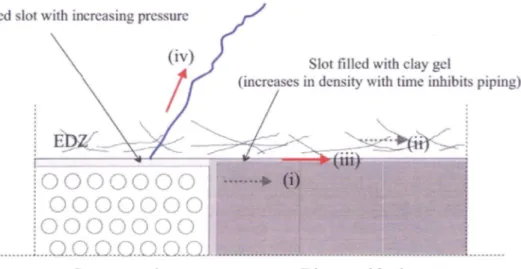
SKB/Posiva have identified several possible pathways for the transport of water and suspended buffer material (Figure 5.2).
Figure 5.2 Potential paths for the transport of water and sus-pended buffer material (ii), (iii) and (iv). In the case of path (i), suspended buffer material would be fil-tered and unable to migrate (SKB 2008, TR-08-03).
5.3 BRITE comments
SKB/Posiva have identified a range of processes and effects related to piping and erosion. However, it is too early to be certain that this is comprehen-sive.
SKB/Posiva have presented some scoping calculations on the impact of loss and redistribution of buffer (Smith et al., 2007a, pages 89-90 and Appendix B.4). These are scoping calculations, not detailed calculations of the type commonly used for thermo-hydro-mechanical calculations. Also, some processes have not been assessed in any detail (e.g., gas piping). Key uncer-tainties identified during the scoping calculations include the properties of the excavation-damaged zone (EDZ), the flow paths that may be active, the duration of flows, and how much bentonite can remain in colloidal suspen-sion.
SKB/Posiva recognise that “it is unclear whether all possibilities regarding
piping and erosion can be addressed in such calculations, because of uncer-tainties associated with some of the assumptions. Therefore, these results are not sufficient to give guidance on the design requirements regarding the avoidance of piping and erosion.”
Overall, SKB/Posiva have provided a reasonable picture of the status of knowledge and uncertainties, but the issue is still one of active research, and the assessment of the effects of piping and erosion is not yet comprehensive or complete. It is notable, however, that the KBS-3H assessment calcula-tions do not assume such large buffer mass losses as in the SR-Can Safety Report.
The impact of piping and erosion on long-term safety has been considered in the KBS-3H assessment by assuming that the amounts of piping, erosion and mass redistribution are minor and that the buffer re-homogenises, and by increasing the diffusion coefficient applied to the buffer.
SKB/Posiva’s calculations with an increased buffer diffusion coefficient do not give significantly different results from those of the base case. However, re-homogenisation of the buffer after erosion is a key uncertainty because it may affect buffer densities, swelling pressures, effective diffusivities, canis-ter failure rates and radionuclide transport rates. Further research and as-sessment calculations would be necessary to support the assumption of buffer re-homogenisation, and to determine the impacts if the buffer does not re-homogenise.
In terms of SKB/Posiva’s strategy for addressing the remaining uncertain-ties, SKB/Posiva note that:
• “The evolution of the buffer, including the possibility of erosion by transient water flows (piping) during operations and subse-quent saturation, drying/wetting, impact of iron saturation and cementation due to silica precipitation are all issues requiring more thorough investigation. Limitation of piping and erosion is discussed further in the context of design issues’
• ‘There is currently no adequate quantitative understanding of chemical erosion of the buffer following the potential penetra-tion of dilute glacial meltwater to repository depth”
Although SKB/Posiva recognise the need for further work, in the reports reviewed they have not described a detailed systematic programme or plan for resolution of these uncertainties. With respect to completeness, SKB/Posiva have provided a reasonable picture of the status of knowledge and uncertainties, but the issue is still one of active research, and the assess-ment of the effects of piping and erosion is not yet comprehensive or com-plete.
Regarding potential impacts, the consequences of piping and erosion on long-term safety has been considered in the assessment in a limited way and assumptions have been made that need further support. Finally, SKB/Posiva recognise that resolution of this topic will need for further work, but in the reports reviewed they have not described a detailed systematic programme or plan for resolution of these uncertainties.
6.
Sealing of deposition
drifts
6.1 Issue description
The deposition drifts must be sealed to prevent or acceptably minimize the inflow of groundwater from the fractured host rock and thus minimize the potential for piping and erosion of the buffer material. The horizontal orien-tation of the KBS-3H conceptual design presents both challenges and oppor-tunities for sealing that are similar or could be different than those for the KBS-3V conceptual design.
6.2 SKB/Posiva’s perspective
The 300 m long horizontal drift with its supercontainers will be filled and sealed using Distance Blocks, Filling Blocks, and Compartment Plugs. In addition, Drift End Plug closes off the whole drift and separates it from the
Deposition Niche, which in turn will be filled and closed with bentonite blocks and pellets, in the same way as for the KBS-3V.
As described above, three different design concepts are under consideration, namely the basic design, BD, the artificial wetting and air evacuation design, DAWE, and the semi tight compartments design, STC.
All of the designs are preliminary, but the BD design is claimed to be at a more detailed stage of development. However, the BD design was found not to be robust (SKB/Posiva conclude that “the design is not robust, includes
severe functional uncertainties and should not be considered a viable alter-native”). In all cases further experiments are likely to be needed, not least to
help select which of the designs will be used.
6.3 BRITE comments
The above-mentioned different key components are each evaluated sepa-rately below, following the scheme for evaluation specified in Section 1 of this report.
6.3.1 Distance blocks
These blocks are being placed between supercontainers in sections where the inflow of water is less than 0,1 l/min, with the intention that they shall
ab-sorb water, swell and seal the drift between the supercontainers. The re-quirements and the design differ, depending on whether BD, DAWE or STC will be used. In particular, fixing rings will be used with the DAWE design, and sealing rings with the STC design.
The requirements and functions of the distance blocks are clearly stated (they should be used in tunnel sections where the inflow is less than or equal to 0.1 l/min), but the basis for the derivation of this value of inflow is not very clear.
The placement of the distance blocks is clearly outlined, although, many aspects remain to be addressed and solved. The wetting phase is perhaps the most important and critical issue to be addressed, especially depending on whether BD, DAWE or STC will be used. Also, the emplacement of the sealing/fixing rings is not resolved and needs further testing and develop-ment.
Regarding long-term safety, the distance blocks are important for separating the supercontainers so that the temperature is kept within appropriate limits, for inhibiting water flow between supercontainers, and for limiting bentonite piping and erosion.
Currently, SKB/Posiva’s overall strategy for resolving these issues is not presented in sufficient detail to allow evaluation of future plans to address these various questions.
6.3.2 Filling blocks
Filling blocks will be used for unsuitable sections of rock that are not sealed with compartment plugs. Filling blocks will be used where water inflows are 0.1 to 1.0 l/min over a 10 m length of drift.
Trial filling blocks have been manufactured and different designs are being considered, mainly related to the size of the gap between their outer surfaces and the host rock, depending on whether the BD, DAWE or STC design will be used.
SKB/Posiva seem to have identified all of the relevant issues, but it is somewhat unclear whether it has been proven that the filling blocks can be manufactured and compressed to the right densities.
Although plans for the manufacturing, transportation and placing of the fill-ing blocks seem to be adequately developed, they have not yet been satisfac-tory tested and much remains to be proven when it comes to their function-ing and ability to fulfill the relevant criteria.
SKB/Posiva have given a comprehensive picture of the problems encoun-tered and the activities needed, although much development remains to be done related to the wetting system, especially the withdrawal of the pipes in the DAWE design.
Overall, the concept of using filling blocks seems to be feasible as well as practically achievable, but the system for wetting of the blocks needs to be resolved.
Regarding long-term safety, the filling blocks have a great impact as they seal off and prevent flow of water between the supercontainers. They also restrict flow of water from the rock into the drift by being so impermeable that flow of water in an intersecting fracture is almost solely confined to the fracture itself.
SKB/Posiva have indicated that further full scale testing will be done, which definitely is needed to prove the functioning of the Filling blocks.
6.3.3 Compartment plugs
Compartment plugs will be used to seal off drift sections where water in-flows are still >1 l/min over a 10 m length of drift after grouting. Thus, the performance of this component of the KBS-3H design has important impli-cations with respect to long-term safety.
The design of the compartment plugs is still in progress and demonstration tests are planned at the Äspö underground research laboratory. SKB/Posiva seem to have provided adequate information regarding future testing and demonstration for this component. It seems that SKB/Posiva have identified the key issues relating to emplacement and wetting of the compartment plugs and no obvious gaps remain.
However, currently, the limits of groundwater inflow are not decided, nor are the DAWE design pipe removal techniques finalized. Finite-element analyses have been made for the design of the compartment plug, but these do not give sufficiently detailed information on several practical issues to further evaluate this component.
6.3.4 Drift end plug and drip shields
At the end of each drift, a drift end-plug seals the drift from the deposition niche. Different designs consisting of steel, or alternatively a low-pH con-crete plug, or a combination of both have been considered by SKB/Posiva. Drip shields will be used to delay wetting of the supercontainers, distance blocks and filling blocks.
The conceptual advantages and disadvantages associated with the different design alternatives for the drift end plugs seem to be well understood. Three different designs of the low pH concrete plug have been considered (fric-tional, notch and wedge shaped notch) as well as a cement-grouted rock plug.
The different designs of the drift end plugs have been analyzed, and experi-ences from other manufactured, larger concrete plugs appear positive. The potential need for temporary steel plugs to avoid early wetting and swelling movements is identified.
Although the specific designs for the different alternatives of the compart-ment plugs have not been tested for the current KBS-3H assesscompart-ment, tests from larger drifts have been successful and suggest that emplacement should be fairly straightforward.
The design of the drip shields is comparatively simple and straightforward. Their functioning has been tested and found satisfactory, but further devel-opment would seem to be necessary for the BD design alternative if this was to be taken forward.
Once the choice between the BD, DAWE and STC designs is made, full-scale manufacturing and testing should be straightforward and the strategy is therefore satisfactory.
6.3.5 Deposition niche
The deposition niche is supposed to be 15 to 25 m long and is expected to be filled with bentonite blocks in the bulk of the niche complemented, with pellets emplaced between the blocks and the tunnel wall. Several major issues remain to be addressed and solved, including:
• a firm horizontal base for the floor of the blocks;
• prevention of wetting and swelling until the full tunnel section is filled with bentonite;
• adequate densities in the pellets for different wetting intensities in different areas of the niche;
• adequate densities of the pellets section.
Regarding completeness, the overall information presented is inadequate at this time and the depth of treatment is unsatisfactory as many problems re-main unsolved and need to be addressed.
It is hard to determine the feasibility and practicality of backfilling the depo-sition niches at this time because of the limited depth of treatment of the problem in the SKB/Posiva reports examined. Consequently feasibility and practicality must be considered to be an open question.
It is obvious that successful closure of the deposition drifts and of the rest of the tunnels is vital to the long-term safety for the whole repository.
SKB/Posiva’s strategy for resolving these issues is unclear but will appar-ently be discussed in later reports.
7.
Corrosion of steel
components external to the
canister
7.1 Issue description
The corrosion of mild steel components (e.g., basket, feet) of the KBS-3H design external to the copper canister are of concern because this corrosion process can lead to several different types of impacts, including
• chemical interaction with contacting smectite minerals of the bentonite buffer,
• generation of a separate hydrogen (H2) gas phase, and
• formation of iron corrosion products having significantly greater molar volume than the initial mild steel components.
Therefore, the reaction mechanism, reaction rate, and specific reaction prod-ucts from the corrosion of mild steel and potential impacts from such corro-sion present obvious differences between the KBS-3H and KBS-3V concep-tual designs.
7.2 SKB/Posiva’s perspective
A steel supercontainer (or basket) is estimated by SKB/Posiva to corrode within a few thousand years (SKB, 2008, TR-08-03, page 42). Under an-aerobic conditions in water the expected corrosion reaction would be
H O Fe O H e Fe 4 8 8 3 2 3 4 (7-1)
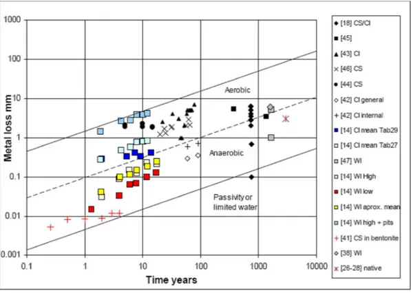
with further recombination of hydrogen atoms to produce hydrogen gas. The wall thickness of the supercontainer is set at 8 mm. Figure 7-1 shows the collection of data points by Crossland (2005) on the corrosion rate of iron in different soils. Based on these data, the estimate of a lifetime of a few thousand years is plausible for the supercontainer of the KBS-3H conceptual design.
Figure 7-1 Plot of metal-loss measurements vs. test duration for mild steel under different environmental conditions (Crossland, 2005). Dashed straight lines indicate three different constant-corrosion rates.
Two main long-term safety related issues arising as a consequence of super-container corrosion have been identified by SKB. These are:
• the impact of steel corrosion products on mass transport. • the effects of gas from the corrosion of steel components. The iron from corrosion is suggested to interact with bentonite forming "iron-bentonite" and, thus, changing bentonite properties at the outer layer of the buffer. The extent of this effect may be evaluated by simple mass bal-ance calculations. Estimates by Wersin et al. (2007) and Wersin and Snell-man (2008) using mass balance state that a maximum 10-30% of montmoril-lonite in bentonite could be transformed. A more advanced reactive transport model predicts that the thickness of a non-swelling layer could be a few cen-timetres. Although there are uncertainties with regard to the extent of the alteration and its effects on properties of the outer layer of buffer, the meas-ures taken and planned by SKB/Posiva to clarify this area are considered satisfactory. The practical question is whether the alteration of the external layer to the above-mentioned extent will jeopardise the overall functions of the buffer.
The effects of H2 gas production from steel corrosion would be the follow-ing:
• slowing buffer saturation (because of the 2° drift inclination gas may collect at the far end of the drift and/or at the compartment plug location).
• reduction of Fe3+ to Fe2+ within the bentonite, which would in-crease the hydraulic conductivity of the buffer dramatically (Carlson et al., 2006).
• alteration of pore water chemistry, e.g., effect on sulphate to sulphide reduction by microbial activity.
• production of gas pathways that may cause or promote affect piping and or erosion of the buffer.
The above-mentioned possible effects of H2 gas have been noted by SKB/Posiva, but a clear research plan on how to address them is mostly lacking.
If oxygen is available for iron corrosion (e.g., dissolved in the groundwater) the resulting corrosion reaction would not produce hydrogen. This is the expected condition during the early phase of repository development, until the oxygen resources are depleted. The overall corrosion reaction in this phase would be:
2 2
2
2
2
(
)
2
Fe
O
H
O
Fe
OH
(7-2)and thus no hydrogen production would take place. The empty space in the KBS-3H deposition tunnel can be estimated to be less than 100 m3, with an average 5 cm distance between the supercontainer and the rock. If filled with air, this volume would have roughly 1000 mol of O2, while if filled with oxygen saturated water, it would contain roughly 150 moles of O (as OH-). According to reaction (2) one mol of O2 would consume 2 moles of Fe. One supercontainer weighs roughly 1000 kg, corresponding to about 18000 mol of Fe. Thus it is clear that only a small part of the supercontainer would be corroded via reaction (2), and most of the corrosion would take place via reaction (1), producing hydrogen gas as a reaction product. This applies probably even if one accounts for the oxygen in the air traps left in the other parts of the disposal vault.
To avoid potential problems with the iron/bentonite interactions and gas generation due to corrosion, titanium has been investigated as a substitute metal.
7.3 BRITE comments
SKB/Posiva have presented a full and detailed description of expected iron corrosion processes, and have linked these to the possible consequences in terms of the formation of iron-rich smectite in the buffer, the generation of hydrogen gas, and the formation of volumetrically expansive iron corrosion products.
The effects of corrosion on bentonite are discussed in Section 8, and the effect of gas generation in Section 9. It is also noted that there will be a marked expansion in molar volume in the corrosion of steel supercontainer and cast iron components to form iron corrosion products. How such expan-sion of solid material might be accommodated within the engineered barrier system and near-field rock has yet to be adequately assessed by SKB/Posiva for the KBS-3H design concept.
8.
Effects of steel
corro-sion on bentonite and
ra-dionuclide transport
8.1 Issue description
In the KBS-3H design, after a relatively short period during which oxygen in the excavations is consumed and reducing chemical conditions are attained, steel components external to the canister will be subject to anaerobic corro-sion and will release Fe(II) to the buffer pore water. The subsequent interac-tions of Fe(II) with bentonite, could potentially include:
• saturation of ion exchange/sorption sites with Fe2+ (Charlet and Tournassat, 2005; Géhin et al., 2007);
• mineral transformation of smectite to non-swelling sheet sili-cates (Savage et al., in press). Although mineral transformation of the buffer is expected to proceed slowly due to the slow ki-netics of the transformation processes, there is evidence from some laboratory experiments that these processes can proceed rapidly, even at relatively low temperatures (Lantenois et al., 2005; Milodowski et al., 2009);
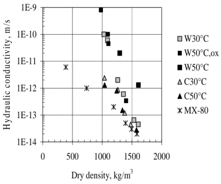
• perturbation of buffer physical properties, such as decreased swelling and/or increased hydraulic conductivity. Experiments investigating the corrosion of steel in compacted bentonite have shown that swelling may be affected (Milodowski et al., 2009) and that hydraulic conductivity may be substantially increased on a relatively short timescale (Carlson et al., 2008).
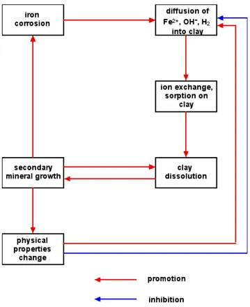
An essential feature of these interactions is that they are strongly coupled in a non-linear fashion (Figure 8-2):
• anaerobic corrosion of steel supplies ferrous ions and hydrogen gas at the interface with bentonite. Sorption of ferrous ions may act as a ‘pump’, driving steel corrosion. Migration of pulses of gas through bentonite will provide a pathway for aqueous spe-cies such as dissolved iron.
1E-14
1E-13
1E-12
1E-11
1E-10
1E-9
0
500
1000
1500
2000
Dry density, kg/m
3H
y
d
ra
u
li
c
c
o
n
d
u
c
ti
v
it
y
,
m
/s
W30°C
W50°C,ox
W50°C
C30°C
C50°C
MX-80
Figure 8-1 Comparison of hydraulic conductivity of unaltered MX-80 bentonite (crosses) with samples altered in corrosion experiments at 30 and 50 °C conducted by Carlson et al. (2008).
Figure 8-2 Iron-bentonite interactions proceed through a cou-pled, non-linear process.
• Ion exchange/sorption of Fe2+ on clay will retard its migration through the bentonite, but may be linked to long-term minera-logical transformation processes.
• Corrosion of steel may be linked to smectite transformation through chemical reduction of structural Fe3+ in the clay (Lantenois et al., 2005; Wersin et al., 2008).
• Anaerobic corrosion of iron, coupled with clay transformation processes serve to increase pore fluid pH, thus accelerating clay dissolution: 2 2 + 2 2
10H
2Mg
2Na
6OH
20SiO
ne
5Berthieri
6Smectite
O
20H
10Fe
• Transformation of montmorillonite to non-swelling minerals will change the physical properties of the bentonite, potentially further enhancing transport through the clay.
It is, thus, important to incorporate this strong coupling between different processes in modelling of the iron-bentonite system, and moreover, not to focus on individual sub-systems without due regard to process coupling.
8.2 SKB/Posiva’s perspective
Overviews of iron-bentonite interactions are described in the Process Report (Gribi et al., 2008) and Summary Report (Smith et al., 2008) and, in more detail, in a number of underlying reports: in a literature review (Marcos, 2003); in a summary of the status of international research (Wersin and Snellman, 2008); as applied to the Olkiluoto Site (Wersin et al., 2008), as linked to gas behaviour (Johnson et al., 2008), and in evidence from steel corrosion experiments in compacted bentonite (Carlson et al., 2008; Milodowski et al., 2009). SKB/Posiva’s broad conclusions from these stud-ies are that (Gribi et al., 2008, p. 251):
• “Chemical alteration may adversely affect swelling, hydraulic and rheological properties of the buffer in the outer region. In particular, enhanced hydraulic conductivity of the outer region of the bentonite may result, which could increase the transport of detrimental solutes to the canister or increase the rate of transport of radionuclides from the canister in case of a release. Significant uncertainties remain in the understanding of the overall impact on the affected region of the buffer, including the extent and nature of neo-mineral formation and the degree of changes in hydraulic conductivity, plasticity and swelling pres-sure of the affected zone. In addition, a possibly lower density in this region could permit more significant microbial activity, a process that is expected to be of little relevance in denser buffer material. The present treatment of the transport properties of the outer buffer region in safety assessment calculations (repre-sented as a mixing tank rather than a zone of somewhat in-creased hydraulic conductivity) to deal with these various im-pacts is very conservative, as explained in the KBS-3H Ra-dionuclide Transport Report.
• An additional potential consequence of the iron/bentonite inter-action is the high occupation by Fe(II) of sorption sites in the outer part of the buffer, which could reduce sorption of some radionuclides. However, the reduced sorption capacity of ben-tonite surface is largely compensated by that resulting from the formation of iron corrosion products (mainly Fe3O4), which
would act as a sink. The long-term evolution of such corrosion products and the fate of the sorbed radionuclides are unclear.”
SKB/Posiva further assess the problem by quantitative analysis with limiting cases based on mass balance and transport considerations (Gribi et al., 2008 based on Wersin et al., 2008). SKB/Posiva conclude that (Gribi et al., 2008, p. 135): “the reactive transport calculations indicate limited migration of the
Fe(II) front, and an even more limited zone of clay alteration even after time periods > 100 000 years. This is mainly due to the low Fe(II) gradient be-tween the iron source and the buffer, the strong sorption of Fe(II) to the clay, and iron precipitation reactions leading to partial clogging. The ad-verse effects on the swelling buffer material are thus spatially limited to the outermost few cm near the buffer-rock interface for very long periods”.
zone remained within a few cm, even for very unfavourable bounding as-sumptions. The zone of altered montmorillonite for this case extends to about 5 cm into the buffer after 500 000 years” (Gribi et al., 2008, p. 135).
In the KBS-3H Radionuclide Transport Report (Smith et al., 2007), SKB/Posiva consider that the impact of iron-bentonite interaction is treated in a simplified and conservative manner by considering two different buffer domains: an inner part that is not affected by iron-bentonite interactions; and an outer part treated as a ‘mixing tank’. The extent of the bentonite alteration zone in the calculation cases is 0 % (but with altered transfer coef-ficients), 10 %, and 50 % of bentonite thickness. SKB/Posiva believe that this approach, in which the altered buffer has essentially an infinite hydraulic conductivity, is highly conservative (Gribi et al., 2008, p. 139).
Nevertheless, SKB/Posiva believe that considerable uncertainties exist re-garding iron-bentonite interactions (Gribi et al., p140) so that:
• further experimental work should include measurements of swelling pressure and hydraulic properties, including gas trans-port properties of altered bentonite.
• the potential effect of H2 on Fe-clay interactions and on reduc-tion of structural iron in smectite should be experimentally in-vestigated.
• from a modelling perspective, it would be useful to include reac-tion kinetics for smectite transformareac-tion in the KBS-3H concep-tual model to obtain a more realistic description of the evolution of the iron front.
8.3 BRITE comments
BRITE concurs with SKB/Posiva’s view that there are continuing uncertain-ties regarding the precise nature and extent of iron-bentonite interaction and associated impacts, but BRITE considers that the quantitative calculations conducted by SKB/Posiva to investigate the possible extent of the effects of this process involve questionable (non-conservative) boundary conditions:
• The choice of Fe solubility-limiting solids at the corroding steel surface (amorphous FeS or siderite) are inconsistent with SKB/Posiva’s own recent experimental data where iron oxyhy-droxide has been identified as a discrete phase on corroding steel in compacted bentonite (Figure 4-7 in Milodowski et al., 2009). The choice of less soluble FeS/siderite inevitably pro-duces a low concentration gradient across the bentonite to drive diffusion. The selection of iron hydroxide as a model variant would produce an Fe2+ concentration at the supercontainer boundary two orders of magnitude greater than those selected by SKB/Posiva and would represent a more conservative (but still realistic) boundary condition.
• There is strong evidence (again, from SKB/Posiva’s own ex-perimental work) that the physical properties of compacted
ben-tonite in contact with steel degrade over very short timescales (3 years). For example, samples of bentonite from corrosion ex-periments (e.g. Carlson et al., 2008) show increased hydraulic conductivity after only 3 years of reaction. Also, new detailed petrographic observations of compacted bentonite from corro-sion experiments carried out by SKB/Posiva revealed that ben-tonite, strongly enriched in Fe close to the corroding steel, dis-played increased shrinkage behaviour compared to the lower-Fe bentonite matrix further away from the corroding wires
(Milodowski et al., 2009). Although bulk changes in porosity were linked to changes in diffusivity in some of SKB/Posiva’s calculations, these model variants are unlikely to have properly captured the effects of increased hydraulic conductivity and de-creased swelling measured/observed in laboratory experiments. • Detailed mineralogical investigations of compacted bentonite
from steel corrosion experiments show greatest penetration of Fe into the bentonite matrix along hairline microfractures that radiate outwards from the corroding metal (Figure 8-3). Milo-dowski et al. (2009, p52) consider that: “The early formed
frac-tures may have represented potentially important pathways for gas and solute transport during the course of the experiments. The irreversible shrinkage of the bentonite, as a result of inter-action with Fe released from corroding iron or steel may there-fore be significant in evaluating the long-term behaviour of the bentonite seal and the transport of gas and solutes around cor-roding waste canisters emplaced in bentonite backfill”. Indeed,
the Process Report (p 138) notes that: “the macroscopic
struc-tures of the alteration products are probably more permeable than the remaining montmorillonite, and will function as prefer-ential paths”, and “while the effect of gas and its penetration of intact buffer is relatively well known, there is little or no under-standing of how Fe-saturated or otherwise chemically altered smectite clay lets gas through. It is known, however, that the microstructural constitution of Fe-saturated MX-80 is charac-terized by channels, meaning that gas can get through at lower pressures” (Gribi et al., 2008, p 138). Although geometrical
properties of the KBS-3H design may prevent gas from creating pathways through the compacted bentonite during corrosion of the supercontainer shell, it is clear that shrinkage cracks in al-tered bentonite may create preferential pathways for further transport of ferrous ions and a ‘feedback loop’ for further altera-tion.
Figure 8-3 Back-scattered electron photomicrograph of a cor-roded steel wire (white) in compacted bentonite. The bentonite around the wire shows a halo of al-teration (light grey) that also penetrates further into the bentonite clay matrix (darker grey) along mi-crofractures. From Milodowski et al. (2009).
• As illustrated in Figure 8-2, iron-bentonite interaction is a strongly coupled process, such that it is relatively uninformative to separate ‘sub-systems’ for quantitative analysis. For exam-ple, Wersin et al. (2008) present several cases examining only diffusion-sorption in bentonite, together with a number of cases incorporating clay hydrolysis reactions plus sorption, but only one case where both iron corrosion and clay hydrolysis reactions were included. The exclusion of the pH-dependency of clay dis-solution rates limits the usefulness of this latter simulation. In summary, although a lot of basic research has been conducted already, further work is necessary including:
• physical properties measurements of altered bentonite; • more realistic modelling;
• assimilation of recent mineralogical work by Milodowski et al. (2009).
The potential impacts of this process are well recognized by SKB/Posiva. The bounding analyses reported in Smith et al. (2008) provide a useful
be-ginning point for examination and quantification of such impacts, but con-siderably more realistic assessment of the extent of alteration still need to be conducted. The resolution of the issue may be made with a combination of additional R&D and additional bounding analyses, or consideration could be given to eliminating the issue by using passivating-type metals, such as stainless steels, Ni-alloys, or titanium.
9.
Impact of gas from the
corrosion of steel
compo-nents external to the
canis-ter, gas flow and
implica-tions
9.1 Issue description
Hydrogen gas will be produced by anaerobic corrosion of steel repository components. The gas pressures that will be reached in the drifts strongly depend on the rates of gas generation and the gas transport capacity of frac-tures in the host rock.
Gas pressures may delay water inflow and prevent the buffer reaching full saturation. If the process of gas evolution lasts longer than the time for can-ister breach by corrosion, radionuclides might be released into a buffer that is not fully saturated.
Pressures will vary along the drifts and could cause transient flows (e.g., along the buffer-rock interface and through the EDZ), which could cause piping and buffer erosion, loss of swelling pressure and lead to spalling.
Hydrogen gas may also promote microbial sulphate reduction, and this may enhance canister corrosion rates.
The presence of a discrete gas phase may affect water flows in the geo-sphere, and this could also affect radionuclide transport.
9.2 SKB/Posiva’s perspective
The main source of hydrogen gas is the supercontainer shells, but a smaller amount of additional gas will be produced as a result of the corrosion of compartment plugs, fixing rings, spray and drip shields.
Based on the possible range of corrosion rates, SKB/Posiva suggest that gas production will occur for a period of a few thousand years to a few tens of thousands of years.