Report number: 2011:16 ISSN: 2000-0456 Available at www.stralsakerhetsmyndigheten.se
Modelling of ultrasonic testing
of cracks in cladding
2011:16
Author: Per-Åke Jansson
Anders Boström
SSM perspective Background
During the last two decades, SSM has supported research to develop a model for the non-destructive test situation based on ultrasonic techni-que. Such a model is important in many ways, for example to supplement and plan experimental studies and to perform parametric studies in qua-lification situation. Modeling can be a useful tool when the inspection system shall be technically justified. Many functions have been added to the model UTDefect and in this step propagation of ultrasound and sig-nal responses from defect in the cladding of austenitic steel are studied.
Objectives
Pipes and components in nuclear power plants are often equipped with a cladding material to prevent material degradation by the influence of media on the surface. This cladding material, often anisotropic, makes the ultrasonic examination more difficult. This project was set up to bet-ter understand the phenomena and model the propagation and defect scattering of the ultrasonic signal in this kind of material combination.
Results
The report describes work that has been performed to model the scat-tering by cracks in a cladding in the full three-dimensional case. The cladding can be corrugated in the boundary between base material and cladding.
The results shows that the corrugated interface can have important and in some cases large effects on the signal response. The result depends crucially on the parameters chosen for the corrugation also the material properties can affect the results.
Need for further research
There is a need for further work within the research field modeling of ultrasonic, to be able to develop and assess the reliability of non-de-structive inspection systems capability to detect, characterize and size defects in components at nuclear power plants.
Project information
Contact person SSM: Richard Sundberg Reference: SSM 2008/55
2011:16
Author: Per-Åke Jansson and Anders Boström
Chalmers University of Technology, Göteborg
Date: April 2011
Report number: 2011:16 ISSN: 2000-0456 Available at www.stralsakerhetsmyndigheten.se
Modelling of ultrasonic testing of
cracks in cladding
This report concerns a study which has been conducted for the Swedish Radiation Safety Authority, SSM. The conclusions and view-points presented in the report are those of the author/authors and do not necessarily coincide with those of the SSM.
Contents
Summary ... 2 Sammanfattning ... 4 1. Introduction ... 5 2. Theoretical considerations ... 8 3. Numerical results ... 10 4. Conclusions ... 17 References ... 18 SSM 2011:162
Summary
Nondestructive testing with ultrasound is a standard procedure in the nuclear power industry. To develop and qualify the methods extensive experimental work with test blocks is usually required. This can be very time-consuming and costly and it also requires a good physical intuition of the situation. A reliable mathematical model of the testing situation can, therefore, be very valuable and cost-effective as it can reduce experimental work significantly. A good mathematical model enhances the physical intuition and is very use-ful for parametric studies, as a pedagogical tool, and for the qualification of procedures and personnel.
The present project has been concerned with the modelling of defects in claddings. A cladding is a layer of material that is put on for corrosion pro-tection, in the nuclear power industry this layer is often an austenitic steel that is welded onto the surface. The cladding is usually anisotropic and to some degree it is most likely also inhomogeneous, particularly in that the direction of the anisotropy is varying. This degree of inhomogeneity is un-known but probably not very pronounced, so for modelling purposes it may be a valid assumption to take the cladding to be homogeneous. However, another important complicating factor with claddings is that the interface between the cladding and the base material is often corrugated. This corruga-tion can have large effects on the transmission of ultrasound through the interface and can thus greatly affect the detectability of defects in the clad-ding.
In the present project two types of planar defects, a strip-like or a rectangular crack, that is situated inside the cladding are considered. The crack can be arbitrarily oriented and situated, but it must not intersect the interface to the base material. The crack can be surface-breaking, and this is often the case of most practical interest, but it should then be noted that this is treated as an internal crack that approaches the surface. This means that the crack mouth remains closed in the limit, contrary to what is to be expected of a real sur-face-breaking crack. At least in pulse-echo testing and not too low frequen-cies (a crack that is smaller than a wavelength), the experience from previous projects is that the difference between the cracks with closed and open mouths is very minor, so that the crack with closed mouth can be used as a good approximation for a real surface-breaking crack.
The problem is investigated with a hypersingular integral equation tech-nique. In this method the integral equation contains a Green‟s function that takes care of all the structure except the crack. This Green‟s function is de-termined with the null field approach, which in itself is a type of integral method. Probe modelling is performed in the usual way by prescribing its traction vector on the component and the action as a receiver is modelled by a reciprocity argument.
Some numerical results are given for a case with an isotropic ferritic base material and an anisotropic austenitic cladding. Only a pulse-echo situation is considered with a line scan showing the amplitude at a fixed frequency.
3
The presence of the cladding and the interface corrugation has a strong in-fluence in some cases.
This project has been supported by the Swedish Radiation Safety Authority.
4
Sammanfattning
Oförstörande provning med ultraljud tillämpas industriellt i kärnkraftsbran-chen vid sökandet efter defekter. För att utveckla och verifiera testprocedurer behövs normalt omfattande experimentellt arbete med testblock. Detta kan ta mycket tid och bli dyrbart och det kräver också en god fysikalisk intuition. En pålitlig matematisk modell av provningssituationen kan därför vara mycket värdefull och kostnadseffektiv eftersom den kan reducera experi-mentellt arbete avsevärt. En bra modell stärker den fysikaliska intuitionen och är mycket användbar för parameterstudier, som ett pedagogiskt hjälp-medel samt vid kvalificeringen av procedurer och personal.
Föreliggande projekt har behandlat modelleringen av defekter i pläteringar. En plätering är ett lager material som satts på som korrosionsskydd, i kärn-kraftssammanhang är detta lager ofta austenitiskt stål som svetsats på. Pläte-ringen är ofta anisotrop och i någon mån är den säkert också inhomogen, speciellt på så sätt att anisotropiriktningen varierar. Denna grad av inhomo-genitet är okänd men antagligen inte så stark, så för modelleringsändamål kan det vara tillräckligt att anta att pläteringen är homogen. En annan kom-plikation med pläteringar är att gränsytan mellan pläteringen och grund-materialet ofta är vågig. Denna vågighet kan ha stor inverkan på transmiss-ionen av ultraljud genom gränsytan och kan alltså kraftigt påverka detekter-barheten av defekter i pläteringen.
I detta projekt studeras en remslik eller rektangulär spricka som ligger i pläteringen. Sprickan kan vara godtyckligt placerad och orienterad, men den får inte skära gränsytan till grundmaterialet. Sprickan kan vara ytbrytande, vilket oftast är det mest intressanta fallet i verkligheten, men det skall då noteras att detta behandlas som gränsen då sprickan närmar sig ytan. Detta betyder att sprickmunnen förblir sluten, tvärtemot vad som kan förväntas av en verklig ytbrytande spricka. Åtminstone vid puls-ekotestning och inte allt-för låga frekvenser (en spricka som är mindre än en våglängd) visar erfaren-heten från tidigare projekt att skillnaden mellan öppen och stängd sprickmun är mycket lite, så att sprickan med sluten sprickmun kan användas som en god approximation för en riktig ytbrytande spricka.
Problemet har behandlats med en hypersingulär integralekvationsmetod. I denna metod innehåller integralekvationen en Greenfunktion som tar hand om hela strukturen utom sprickan. Denna Greenfunktion bestäms med noll-fältsmetoden, som i sig är en typ av integralmetod. Sökarmodellering görs på det vanliga sättet genom att föreskriva spänningsvektorn på komponenten och verkan som mottagare modelleras med ett reciprocitetsargument.
Numeriska resultat ges för fallet med ett isotropt ferritiskt grundmaterial och en anisotrop austenistisk plätering. Bara puls-ekotestning med en sökare som gör en linjesökning vid fix frekvens behandlas. Närvaron av pläteringen och gränsytan har ibland en stark inverkan.
Detta projekt har bekostats av Strålsäkerhetsmyndigheten.
5
1. Introduction
Nondestructive testing with ultrasound is a standard procedure in the nuclear power industry. To develop and qualify the methods extensive experimental work with test blocks is usually required. This can be very time-consuming and costly and it also requires a good physical intuition of the situation. A reliable mathematical model of the testing situation can, therefore, be very valuable and cost-effective as it can reduce experimental work significantly. A good mathematical model enhances the physical intuition and is very use-ful for parametric studies, as a pedagogical tool, and for the qualification of procedures and personnel.
A common anisotropic part in nuclear power components is a cladding, i.e. a layer of material used for corrosion protection inside reactor tanks and other parts. This is often an austenitic steel welded onto the surface to be protect-ed. The handbook by Hudgell (1994) gives a discussion of the problems with this and gives guidelines for the ultrasonic testing of components with clad-dings, see also Chokie (2005) for related issues. Due to the processing a welded cladding is both anisotropic and also somewhat inhomogeneous, primarily in that the direction of anisotropy is varying. For modelling pur-poses it may be a valid assumption to take the material as homogeneous. Another complication is that often the interface between the cladding and the base material is corrugated, typically with a wavelength around 5 mm and a peak-to-peak amplitude of 1-2 mm (Hudgell 1994). The properties of clad-dings can have a large impact on the ultrasonic wave propagation as has been demonstrated in previous SKI projects (Boström, 2004, Boström and Zagbai, 2006). The purpose of the present report is to describe the inclusion of strip-like and rectangular cracks in a cladding into the computer program UTDefect, and this is thus an extension of previous work in two dimensions, see Boström and Zagbai (2006; this is not included in UTDefect as this pro-gram only has three-dimensional situations). For a complete description of all the mathematical details of the present project see Jansson (2010).
The computer program UTDefect has been developed for more than a dec-ade at Chalmers University of Technology, presently at the Department of Applied Mechanics. The progress has been reported in a number of SKI reports (Boström, 1995, 1997, 2000, 2001, 2002, 2004, Boström and Jansson 1997, 2000, Boström and Zagbai, 2006) and also in papers in scientific jour-nals and at conferences, and in PhD theses. The program models the ultra-sonic testing of a single defect in a component. The defect may be located close to a planar back surface, but not too close to the scanning surface. The defects should be of simple shape, like side-drilled hole, spherical or sphe-roidal pores, circular, strip-like and rectangular cracks. Also a strip-like sur-face-breaking crack is possible. Some of the cracks may be rough or partly closed due to a compressive stress. In most cases the component is assumed to be isotropic, but for strip-like and rectangular cracks it is also possible with an anisotropic component. In all cases the component is assumed ho-mogenous, but can have damping in the form of viscoelastic losses (which could model, e.g., grain scattering effects). The ultrasonic probes are of standard type, primarily contact probes of any type, angle, frequency, and with elliptic or rectangular effective contact area. Immersion testing is
6
ble and the probes may also be focussing. The scanning is assumed to take place in a rectangular mesh on the surface of the component (or in the fluid in case of immersion testing). Results can be obtained in the form of A, B, and C scans, and it is also possible to obtain frequency data.
The methods used in UTDefect to solve the ultrasonic propagation and scat-tering problems are various types of integral and integral equation tech-niques. For side-drilled holes and spheres standard separation-of-variables is employed. A transmitting probe is modelled by the effective traction it exerts on the component, this is usually taken as a constant except for a phase de-termining the angle of the probe (usually called the piston model in the liter-ature). The receiving probe is modelled by an elegant reciprocity argument due to Auld (1979). This is strictly valid only in lossless media, so when small viscoelastic losses are included in the model the argument is not strict-ly valid. It is noted that all methods used in UTDefect are in a sense “exact” in that they can, in principle, give solutions with arbitrarily high accuracy (by taking sufficient number of terms in series, computing integrals suffi-ciently accurately, etc.). It should remembered, however, that this is within the framework of linear elasticity, only viscoelastic losses, perfect geometry, like infinitely thin cracks, piston model for probes, etc. Still, in many cases the results should be more reliable than solutions depending on the common high frequency approximations, like ray theory, Kirchhoff theory, or diffrac-tion theory. For such methods it may be difficult to ascertain the range of validity in frequency, although the methods often work surprisingly well even at relatively low frequency (meaning that the size of typical defects has a diameter of about one wavelength). UTDefect works in the frequency do-main and time dodo-main results are synthesized at the end by a discrete Fourier transform. However, when C scans are generated it is often enough to use only the centre frequency. This significantly reduces the computational times as typically 100 frequencies are used to synthesize pulses in the time do-main.
An important issue when models and computer programs are developed is of course the validation. For a program like UTDefect this can be done by comparisons with other modelling programs and/or by comparisons with experiments. Through the years some parts (but not all) of UTDefect have been compared in this way (Boström, 1995, Eriksson, et al.,1997, Pecorari 2002, Niklasson, et al., 2006, Jansson and Boström 2009, 2010). In general the agreement is good or fair, typical deviations are in most cases less than 2 dB. In some situations with real fatigue cracks in the near field (Eriksson et al., 1997) the deviations are larger, but this can be attributed both to limita-tions of UTDefect at that time and to the fact that real fatigue cracks were used and these can be both slightly rough and maybe not quite straight or vertical. It is more surprising that comparisons for a spherical void (Niklas-son et al., 2006) show such large discrepancies, about 3-5 dB.
The modelling of anisotropic components is difficult in several ways. The model must include all essential parameters and in particular the stiffness constants that describe the anisotropy. For a transversely isotropic material, which is an adequate model for an austenitic weld material, there are five stiffness constants and for an orthotropic material there are nine (the most
7
general anisotropy has 21 stiffness constants). It is not an easy task to exper-imentally determine these stiffness constants and if the material in addition is inhomogeneous the task becomes more or less impossible. Even if the de-gree of inhomogeneity would be known, which it in practice never will be, it is hard to model this. One alternative is ray tracing (using RAYTRAIM for example) and this gives some insight into the ultrasonic propagation, but it is hard to assess how accurate this method really is. Otherwise one must resort to purely numerical methods like FEM or EFIT, but these become very com-puter intensive in three dimensions. The theses by Halkjear (2000) and Han-nemann (2001) give examples of using EFIT in two dimensions for an in-homogeneous and anisotropic weld (but not a cladding), also including a crack.
8
2.
Theoretical considerations
The methods used to investigate the scattering problems for a crack in an anisotropic cladding with a corrugated interface are now very shortly de-scribed. No formulas are given as the lengthy expressions are given by Jans-son (2010). Here the intention is only to give an overall impression of the methods.
The three-dimensional scattering geometry is shown in Fig. 1. The cladding is the lower material (material 2) which is bounded above with the corrugat-ed interface to the base material (material 1). The probe is performing a rec-tangular scan on the surface of the base material. The interface is assumed to be sinusoidally corrugated in one direction as shown and constant in the other direction. The choice of a sinusoidal corrugation is made for two rea-sons. Firstly, this corrugation is a reasonable model of a real welded clad-ding interface (Hudgell, 1994). It is also a convenient mathematical formula-tion of the interface that is relatively easy to handle, one important reason being that it is a periodic function. The location of the crack is also shown in Fig. 1. For a rectangular crack as shown the two sides are b and c. The orien-tation of the rectangular crack is specified by three Euler angles relative a position where the crack is horizontal with sides along the coordinate axes. In the numerical examples only the tilt of the crack relative the vertical is varied. If the crack is strip-like the height of the crack is b and it is tilted by an angle from the vertical. The corrugated interface is specified by its period a and its peak-to-peak height d. Also the position of the crack relative the hills and valleys of the interface is important. The centre of the crack is situ-ated at the origin of the scanning coordinate system and the translation to the right of a valley of the interface from this position is specified.
Figure 1: The scattering geometry of the cladding and the crack.
Both the cladding and the base material can be anisotropic and this is de-scribed by the stiffness constants Cij (in abbreviated notation with i and j =1,
2, 3, 4, 5, 6) with an additional upper index when it is necessary to distin-guish between the two materials. The density of the materials is also spec-ified. The natural way to specify the anisotropy is to give the stiffness con-stants in the crystal system (the system where the stiffness tensor appears in
9
its simplest form) and then give the orientation of the crystal system. For an austenitic weld the anisotropy can be assumed to be transversely isotropic with the crystal axis (perpendicular to the isotropy plane) in the cooling di-rection of the weld. Then five stiffness constant and three angles of rotation are necessary to fully specify the elastic properties of the material. A real weld will have a cooling direction, and thereby an anisotropy, that is chang-ing, meaning that the material is inhomogeneous. However, this anisotropy is largely unknown in practice and difficult to handle in a model, so here the material is taken as homogeneous. In the numerical examples the crystal axis is taken perpendicular to the scanning surface.
To solve the full problem with the generation of ultrasonic waves at the transmitting probe, propagation to the crack and cladding, scattering (includ-ing multiple effects), propagation back to the receiv(includ-ing probe, and conver-sion to an electric signal that is measured, an approach in a number of steps is taken. The treatment of the transmitting and receiving probes is performed in the same way as in other parts of UTDefect. Thus, a piston model is used for the probes and the radiation from the probe is solved for by Fourier trans-form techniques. The electrical output from the receiving probe is obtained by Auld‟s (1979) reciprocity argument.
The scattering by the cladding and the crack is the most challenging part. This is done in a two-step procedure where first the Green‟s function for the cladding without the crack is determined (a Green‟s function is a solution for a point source). This determination follows the lines in an earlier project where the ultrasonic propagation in a cladding without a crack was investi-gated (Krasnova 2005). In particular, this Green‟s function then includes the scattering by the corrugated interface. This Green‟s function is then em-ployed in an integral equation for the scattering by the crack. This is the same type of hypersingular integral equation which has been used in earlier projects. This allows an efficient solution procedure, but it restricts the shape of the crack to be rectangular or strip-like, and this is the reason for the re-striction to such cracks in the present project. The whole numerical proce-dure becomes rather involved, the most tricky parts being the computation of integrals that are not so well behaved.
10
3. Numerical results
In this section some numerical examples showing line scans are given to illustrate the effects of the cladding on the crack scattering response. There are many parameters to vary, but only some of those that are believed to be of most interest have actually been varied.
The geometry is given in Fig. 1. The upper base material is chosen as an isotropic steel and the lower cladding is an anisotropic austenitic steel (weld material). The thickness of the base material is 30 mm and the thickness of the cladding is 5 mm. The base material is an isotropic ferritic steel with pressure wave speed 5.9 mm/s and shear wave speed 3.2 mm/s and density 8400 kg/m3. The cladding is a weld material with density 8500 kg/m3 that is
transversely isotropic with stiffnesses C22 = C11 = 216, C33 = 250, C55 = C44 =
100, C12 =115, and C23 = C13 = 115, all measured in GPa. The stiffnesses are
given in the crystal system and to fully specify the material also the orienta-tion of the crystal system must be given. As menorienta-tioned above the isotropy plane (the 12 plane) is taken as parallel to the back side.
The interface between the cladding and the base material is sinusoidally corrugated with a period of a = 5 mm. The peak-to-peak height of the corru-gations is 0, 1, or 2 mm. The crack is situated in the cladding. The centre of the crack is located in the middle of the cladding. In the „default‟ situation the crack centre is just below a valley of the corrugations and the corrugation peak-to-peak height is 2 mm. Translations of the corrugation will be consid-ered, one, two, or three quarters of the period (i.e. 1.25, 2.5, or 3.75 mm). The crack is strip-like with a width 3 mm or rectangular with varying sides, given as the side in the scanning plane (the height) and the other side (paral-lel to the back side; the width), given in that order. The crack can be vertical or tilted, but the other two possible rotation angles are not used. This means that the crack is never surface-breaking, although the distance between the lower crack tip and the back surface is only 0.5 mm when the crack is verti-cal and 3 mm. From previous experience it is known that this type of near-surface crack gives a signal response very similar to a near-surface-breaking crack as long as a pulse-echo setup is used and the frequency is not too low (the crack should be at least about half a wavelength).
Only a single probe in pulse-echo is used which performs a line scan (C scan) on the base material. The probe is square with side 10 mm and it is operating at the fixed frequency 1 or 2 MHz. A shear SV probe with angle 45 degrees is assumed. The results are normalized with a side-drilled hole of diameter 3 mm and depth 33 mm in the base material.
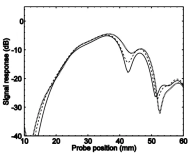
First the frequency 1 MHz is considered. The influence of the corrugations is investigated by varying the corrugation amplitude and translation. Figure 2 shows the results of varying the amplitude for a rectangular vertical crack with height 3 mm and width 6 mm. Three different amplitudes are shown: 0 mm (full-drawn curve), 1 mm (dashed), and 2 mm (dotted). In this case the influence of the corrugation amplitude is minor, the peak amplitude can vary with about 1 dB.
11
Figure 2: Signal response at 1 MHz from a vertical 3 by 6 mm rectangular crack with differ-ent amplitudes on the cladding corrugation: 0 mm amplitude (full-drawn), 1 mm amplitude (dashed), 2 mm amplitude (dotted).
Figure 3 shows the signal response in the same situation as in Fig. 2 with the exception that the interface is corrugated with a peak-to-peak value of 2 mm and the translation of the interface is varied, i.e. so that the crack is situated below a valley (full-drawn), or hill (dotted), or two intermediate cases. Also in this case the effects of the corrugations are rather small, the peak ampli-tude varies less than 2 dB between the cases.
Figure 3: Signal response at 1 MHz from a vertical 3 by 6 mm rectangular crack with differ-ent translations of the cladding corrugation: 0 mm translation (full-drawn), 1.25 mm transla-tion (dashed), 2.5 mm translatransla-tion (dotted), 3.75 mm translatransla-tion (dash-dotted).
12
Figure 4: Signal response at 1 MHz from a vertical 3 mm strip-like crack with different am-plitudes of the cladding corrugation: 0 mm amplitude (full-drawn), 1 mm amplitude (dashed), 2 mm amplitude (dotted).
Figures 4 and 5 show the same situations as Figs. 2 and 3, but for a strip-like crack. The effects of the corrugations are even smaller.
Figure 6 shows the signal response for varying widths of cracks with a common height of 3 mm. The cracks are strip-like (full-drawn) and
Figure 5: Signal response at 1 MHz from a vertical 3 mm strip-like crack with different trans-lations on the cladding corrugation: 0 mm translation (full-drawn), 1.25 mm translation (dashed). 2.5 mm translation (dotted), 3.75 mm translation (dash-dotted).
13
Figure 6: Signal response at 1 MHz from a strip-like crack (full-drawn) and three rectangular cracks with height 3 mm and width 6 mm (dashed), 3 mm (dotted), and 1 mm (dash-dotted). The lower wiggly curve is the response from the cladding without a crack.
rectangular with height 3 mm and widths 6 mm (dashed), 3 mm (dotted), and 1 mm (dash-dotted). As expected the larger cracks give a stronger signal response. The lower curve with a wiggly but otherwise constant amplitude is the signal response by the cladding itself, i.e. without any crack. In this case this response is much smaller, about 12 dB smaller, than the response from the smallest crack.
Figure 7: Signal response at 1 MHz from a 3 by 6 mm rectangular crack with different tilts from the horizontal: 0 degree tilt (full-drawn)t, 45 degrees tilt (dashed), 90 degrees (dotted), 135 degrees tilt (dash-dotted).
14
Figures 7 and 8 show the signal response from rectangular and strip-like cracks, respectively, when the tilt of the cracks is varied. For the rectangular crack the variations are not so large, about 4 dB, but for the strip-like crack the difference can be almost 10 dB. By simple arguments one would expect the strongest response for the vertical crack (90 degrees) due to the corner echo, followed by 135 degrees due to specular reflection, and this is con-firmed by Fig. 8.
Figure 8: Signal response at 1 MHz from a strip-like crack with different tilts from the hori-zontal: 0 degree tilt (full-drawn), 45 degrees tilt (dashed), 90 degrees tilt (dotted), 135 degrees tilt (dash-dotted).
Figure 9: Signal response at 2 MHz from a vertical 3 by 6 mm rectangular crack with differ-ent amplitudes on the cladding corrugation: 0 mm amplitude (full-drawn), 1 mm amplitude (dashed), 2 mm amplitude (dotted).
15
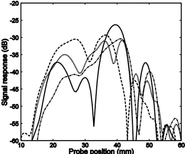
The frequency 2 MHz is next considered. In this connection it can be worthwhile to remember that doubling the frequency is equivalent to dou-bling all geometrical lengths instead; it is only the product of frequency and length that matters. Figure 9 shows the response when varying the amplitude of the corrugations for a rectangular crack with height 3 mm and width 6 mm. This figure should be compared with Fig. 2 which shows the same vari-ations for 1 MHz. At the higher frequency 2 MHz the amplitude of the clad-ding corrugation is apparently very important whereas at 1 MHz it is not. In the same way Fig. 10 shows the effects of translating the corrugations rela-tive to the crack, This figure should be compared with Fig. 3, and again the conclusion is that the properties of the corrugations are important at 2 MHz but not at 1 MHz.
Figure 10: Signal response at 2 MHz from a vertical 3 by 6 mm rectangular crack with differ-ent translations of the cladding corrugation: 0 mm translation (full-drawn), 1.25 mm transla-tion (dashed), 2.5 mm translatransla-tion (dotted), 3.75 mm translatransla-tion (dash-dotted).
Figure 11 shows the response from four different sizes of a rectangular crack, and as expected the larger cracks give stronger response than smaller ones. Figure 12 shows the response when the tilt of a 3 by 6 mm rectangular crack is tilted at four different angles. In this case the horizontal crack actu-ally gives the largest response, although the difference is not large. This is somewhat counter-intuitive, as the largest response might be expected from a vertical crack (a corner echo) or 45 degrees tilt (a specular reflection).
16
Figure 11: Signal response at 2 MHz from four rectangular cracks of different heights and widths: 3 by 6 mm (dash-dotted), 3 by 3 mm (dotted), 2 by 4 mm (dashed), and 2 by 2 mm (full-drawn).
Figure 12: Signal response at 2 MHz from a 3 by 6 mm rectangular crack with different tilts from the horizontal: 0 degree tilt (full-drawn), 45 degrees tilt (dashed), 90 degrees (dotted), 135 degrees tilt (dash-dotted).
17
4. Conclusions
The present report describes work that has been performed to model the scat-tering by cracks in a cladding in the full three-dimensional case. The clad-ding (and also the base material) can be anisotropic and the interface be-tween the base material and the cladding can be corrugated. To solve the scattering problems a hypersingular integral equation technique is employed. The Green‟s function that plays a central role in this formulation and takes care of the whole structure except for the crack has been calculated by the null field approach following the approach in a previous project. Transmit-ting and receiving ultrasonic probes are treated in the standard way in UTDefect.
The main conclusion that can be drawn from the project is that the corrugat-ed interface can have important and sometimes large effects on the signal response. In the examples shown, large effects due to the corrugations are apparent at 2 MHz but not at 1 MHz. But this conclusion of course depends crucially on the parameters chosen for the corrugations, in this case a period of 5 mm and a peak-to-peak height 2 mm. Also the material properties may play a role, in the examples the contrast in material parameters between the isotropic base material and the anisotropic cladding are not large.
18
References
Auld, B.A., “General electromechanical reciprocity relations applied to the calculation of elastic wave coefficients”, Wave Motion 1, 3-10, 1979.
Boström, A., UTDefect – a computer program modelling ultrasonic NDT of cracks and other defects, SKI Report 95:53, Swedish Nuclear Power Inspec-torate, Stockholm 1995.
Boström, A., Ultrasonic probe radiation and crack scattering in anisotropic media, SKI Report 1997:27, Swedish Nuclear Power Inspectorate, Stock-holm 1997.
Boström, A., User guide to UTDefect, version 3: a computer program mod-elling ultrasonic non-destructive testing of a defect in an isotropic compo-nent, SKI Report 00:44, Swedish Nuclear Power Inspectorate, Stockholm 2000.
Boström, A., Modelling of ultrasonic non-destructive testing in anisotropic materials – rectangular crack, SKI Report 01:51, Swedish Nuclear Power Inspectorate, Stockholm 2001.
Boström, A., User guide to UTDefect, version 4: a computer program mod-elling ultrasonic non-destructive testing of a defect in an isotropic or aniso-tropic component, SKI Report 02:26, Swedish Nuclear Power Inspectorate, Stockholm 2002.
Boström, A., Propagation of ultrasound in claddings, SKI Report 2004:19, Swedish Nuclear Power Inspectorate, Stockholm 2004.
Boström, A., and Jansson, P.-Å., Developments of UTDefect: rough cracks and probe arrays, SKI Report 97:28, Swedish Nuclear Power Inspectorate, Stockholm 1997.
Boström, A., and Jansson, P.-Å., Developments of UTDefect: rough rectan-gualr cracks, anisotropy, etc, SKI Report 00:43, Swedish Nuclear Power Inspectorate, Stockholm 2000.
Boström, A., and Zagbai, T., Modelling of ultrasonic non-destructive testing of cracks in claddings, SKI Report 06:25, Swedish Nuclear Power Inspec-torate, Stockholm 2006.
Chokie, A., White paper: current inspection capabilities for cast austenitic stainless steel piping, Chokie Group International, Inc., Seattle 2005.
Eriksson, A.S., Boström, A., and Wirdelius, H., Experimental validation of UTDefect, SKI Report 97:3, Swedish Nuclear Power Inspectorate, Stock-holm 1997.
19
Halkjaer, S., Elastic wave propagation in anisotropic, inhomogeneous mate-rials – application to ultrasonic NDT, Thesis, Department of mathematical modelling, Technical University of Denmark, Lyngby, Denmark 2000. Hannemann, R., Modeling and imaging of elastodynamic wave fields in in-homogeneous anisotropic media – an object-oriented approach, Thesis, Department of electrical engineering, University of Kassel, Kassel, Germany 2001.
Hudgell, R.J., Handbook on the ultrasonic examination of austenitic clad components, The International Institute of Welding and Joint Research Cen-tre, European Commission, Luxembourg 1994.
Jansson, P.-Å., Wave scattering from a rectangular crack in an anisotropic cladding, submitted 2010.
Jansson, P.-Å., and Boström, A., Simulation of the 2008 ultrasonic bench-marking problems using UTDefect, Rev. Progress Quant. Nondestr. Eval. Vol. 28B, pp. 1968-1972, eds Thompson, D.O., and Chimenti, D.E., Am. Inst. Phys., Melville, N.Y. 2009.
Jansson, P.-Å., and Boström, A., Ultrasonic benchmarking with UTDefect, Rev. Progress Quant. Nondestr. Eval. Vol. 29B, pp. 2149-2156, eds Thomp-son, D.O., and Chimenti, D.E., Am. Inst. Phys., Melville, N.Y. 2010.
Krasnova, T., Jansson, P.-Å., and Boström, A., Ultrasonic wave propagation in an anisotropic cladding with a wavy interface, Wave Motion 41, 163-177, 2005.
Krasnova, T., Elastic wave scattering from corrugated surfaces in aniso-tropic media, PhD thesis, Department of Applied Mechanics, Chalmers Uni-versity of Technology, Göteborg 2005.
Niklasson, J., Boström, A., and Wirdelius, H., Benchmarking – a validation of UTDefect, SKI Report 06:30, Swedish Nuclear Power Inspectorate, Stockholm 2006.
Strålsäkerhetsmyndigheten Swedish Radiation Safety Authority
SE-171 16 Stockholm Tel: +46 8 799 40 00 E-mail: registrator@ssm.se Solna strandväg 96 Fax: +46 8 799 40 10 Web: stralsakerhetsmyndigheten.se
2011:16 The Swedish Radiation Safety Authority has a comprehensive responsibility to ensure that society is safe from the effects of radiation. The Authority works to achieve radiation safety in a number of areas: nuclear power, medical care as well as commercial products and services. The Authority also works to achieve protection from natural radiation and to increase the level of radiation safety internationally.
The Swedish Radiation Safety Authority works proactively and preventively to protect people and the environment from the harmful effects of radiation, now and in the future. The Authority issues regulations and supervises compliance, while also supporting research, providing training and information, and issuing advice. Often, activities involving radiation require licences issued by the Authority. The Swedish Radiation Safety Authority maintains emergency preparedness around the clock with the aim of limiting the aftermath of radiation accidents and the unintentional spreading of radioactive substances. The Authority participates in international co-operation in order to promote radiation safety and fi nances projects aiming to raise the level of radiation safety in certain Eastern European countries.
The Authority reports to the Ministry of the Environment and has around 270 employees with competencies in the fi elds of engineering, natural and behavioural sciences, law, economics and communications. We have received quality, environmental and working environment certifi cation.