Producibility Assessment System
;
Enhancing modularization, robustness and
flexibility.
AUTHOR: Max Jacobson TUTOR: Roland Stolt JÖNKÖPING Month Year
Postadress: Besöksadress: Telefon:
Box 1026 Gjuterigatan 5 036-10 10 00
(vx)
551 11 Jönköping
This exam work has been carried out at the School of Engineering in Jönköping in the subject area Product Development and Materials Engineering. The work is a part of the Master of Science programme. The author takes full responsibility for opinions, conclusions and findings presented.
Examiner: Fredrik Elgh JTH Supervisor: Roland Stolt GKN Supervisor: Petter Andersson Scope: 30
2
ABSTRACT
Developing high-end aerospace components is a complex and highly competitive business. Hence methods for decreasing lead-time, while still providing the same quality and at a lower cost, has to be developed.
This thesis is conducted at Research & Technology - GKN Aerospace in Trollhättan Sweden. A multidisciplinary analysis system known internally as Engineering Workbench, forms the base for implementation of the methods and tools developed in this thesis work. The system applies set-based engineering approach to develop new components. The evaluation of the design space is performed through parametric studies to find relations between the design parameters and performance metrics of the design. The engineering workbench allows GKN to define and evaluate a large design space within a limited timeframe.
This thesis will look to improve the current producibility assessment system within the EWB by increasing the robustness and flexibility of the system. This is done by re-designing the producibility analysis part system and into a modular knowledge-based system that implements various techniques to increase the robustness and flexibility of the system. The re-designed system is automated, flexible and robust and is able to perform user defined weld assessments on a various designs and provides GKN with weld producibility data.
Keywords
Aerospace, Manufacturability Analysis System, Knowledge-Based Engineering, Software Engineering, System Engineering, Robustness, Flexibility, Concurrent Engineering, Set-Based Engineering.
3
CONTENTS
1
INTRODUCTION ... 5
1.1 BACKGROUND ... 6 1.1.1 GKN ... 6 1.1.2 CAD ENVIRONMENT ... 71.1.3 PRODUCT DEVELOPMENT PROCESS ... 7
1.1.4 EWB, EngineeringWorkbench ... 8
1.2 PURPOSE AND RESEARCH QUESTIONS ... 9
1.3 DELIMINATIONS ... 9
1.4 OUTLINE ... 9
2
THEORETICAL BACKGROUND ... 11
2.1 KNOWLEDGE BASED ENGINEERING... 11
2.1.1 KNOWLEDGE-BASED SYSTEMS ... 11
2.1.2 KNOWLEDGE-BASE ... 12
2.2 MODULAR DESIGN IN SOFTWARE ENGINEERING ... 13
2.3 MANUFACTURABILITY ANALYSIS SYSTEM ... 13
2.4 EXPERT SYSTEMS ... 14
2.5 DESIGN OF EXPERIMENT ... 14
2.6 TRANSPERANCY, FLEXIBILITY, TRACEBILITY & ROBUSTNESS IN SOFTWARE ENGINEERING ... 15
2.7 SET-BASED CONCURRENT ENGINEERING ... 16
3
METHOD ... 18
3.1 RESEARCH CLARIFICATION... 19 3.1.1 SUCCESS CRITERIA ... 19 3.2 DESCRIPTIVE STUDY 1 ... 19 3.3 PERSCRIPTIVE STUDY ... 20 3.4 DESCRIPTIVE STUDY 2 ... 204
PREPARING IMPLEMENTATION ... 22
4.1 SYSTEM REQUIREMENTS ... 22 4.1.1 PROBLEM ELABORATION ... 23 4.2 IMPLEMENTATION ... 23 4.2.1 SYSTEM INTEGRATION ... 23 4.2.2 SYSTEM ARCHITECTURE ... 244.2.3 ROBUSTNESS AND FLEXIBILITY (TRANSPARENCY, SCALABILITY, RECOGNISABILITY AND TRACEABILITY) ... 25
4.3 PRINCIPAL SYSTEM STRUCTURE ... 25
4.3.1 ASSESSMENT DEFINITION... 28
4.3.2 COLLECT CAD DATA ... 29
4.3.3 DATA (WELD) EVALUATION ... 30
4
5
RESULTS ... 33
5.1 WELD PRODUCIBILITY ASSESSMENT SYSTEM ARCHITECTURE 34+ 5.2 ASSESSMENT DEFINITION MODULE ... 37
5.2.1 ASSESSMENT DEFINITION INPUT ... 38
5.2.2 NX APPLICATION ... 41
5.2.3 COLLECT CAD DATA MODULE ... 49
5.2.4 DATA EVALUATION MODULE & SYSTEM OUTPUT ... 55
5.3 CASE STUDIES & SYSTEM EVALUATION ... 63
6
DISCUSSION & CONCLUSION... 64
6.1 DISCUSSION OF METHOD ... 64
6.2 DISCUSSION OF FINDINGS ... 65
6.2.1 FLEXIBILITY AND ROBUSTNESS ... 65
6.2.2 FINAL SYSTEM ... 66
6.3 CONCLUSIONS RELATED TO THE RESEARCH QUESTIONS ... 68
6.4 FUTURE WORK ... 68
6.4.1 FLEXIBILITY AND ROBUSTNESS ... 68
6.4.2 FINAL SYSTEM ... 69
7
References ... 70
8
LIST OF FIGURES ... 71
9
SEARCH TERMS ... 74
5
1 INTRODUCTION
The thesis is a part of the Product Development and Materials Master Program at JTH and conducted at and within the Research & Technology department at GKN Aerospace Sweden, Trollhättan. The work in this thesis is done within GKN’s system from their office and covers research regarding GKN’s producibility assessment system. What tools are needed to assess the weld producibility at early design stages? And how can an automated system be developed to perform weld assessments in an ever changing product variation? These are examples of questions that will be discussed and researched in this paper.
Todays’ products are constantly improved using the latest technology, resulting in an ever increasing product complexity. Its therefore common that product development stretches over a wide range of different engineering fields. Hence using a multidisciplinary approach becomes more necessary to be able to develop an optimised product that fulfils the performance requirements. Unfortunately, it’s impossible to optimize a product in all fields, trade-offs have to be made between the requirements and the actual properties of the component. The more data that is available from each field when performing the trade-off, the more accurate the trade-off. GKN implement set-based concurrent engineering in combination with parametric studies to perform the trade-off.
The thesis continues the most recent work performed in this area in two previous theses, both of which have been conducted under JTH for GKN. These theses have researched multidisciplinary analysis systems with focus on producibility and weld assessment in connection to the parameter study. Evaluating the possibilities and discrepancies of applying, and developing, such systems at GKN. Integrating weld analysis as a part of the producibility assessment system will improve the knowledge with an important part while performing trade of studies in the concept phase. The ability to receive weld producibility data at early design stages improves the validity and precision of the trade-off and decreases the lead time by evaluating the producibility at an early stage.
This thesis aims to further develop GKN’s producibility assessment system to enable an efficient and robust method for generating and capturing producibility related data that is to be used when performing the trade-off previously described. The system will be re-designed towards modularization, standardization and including knowledge based decision functionality to reduce integration of engineering decision during the process. The aim for the re-design is to increase the robustness and flexibility of the system to secure the
6
stability when used in the parametric study and enable the system for further development.
1.1 BACKGROUND
In the aerospace industry analysing producibility in early phases is prioritized in product development as the globalisation drives increased competition and a focus on reducing cost.
The most recent thesis work in this area at GKN includes the development of a prototype weld producibility assessment system. The system is developed by (Heikkinen & Müller, 2015) who researched “How can producibility be assessed
for use in a fully automated multidisciplinary Analysis system?”. With the
conclusion that “Producibility in a fully automated Multidisciplinary Analysis
system can be assessed with the implementation of a manufacturability assessment system as described in this report … The described PAS (producibility assessment system) use-case showed promising results. Several challenges in capturing knowledge and connecting the results towards producibility metrics are however identified”. The prototype needs to be
re-developed towards standardization, flexibility and robustness to be compatible with SBCE (set-based concurrent engineering) approach used at GKN.
Another recent thesis contribution is (Pabolu, 2015), who did his thesis within the same scope, weldability analysis and system development. Jönköpings Tekiska Högskola is also currently doing research together with GKN Aerospace in Trollhättan in the form of two projects, “ChaSE” and “Impact”. “ChaSE” focuses on finding flexible product and product knowledge models for rapid response to fluctuating requirements in the design process and “Impact” looks at the capture and maintenance of knowledge.
1.1.1 GKN
GKN Aerospace Sweden AB is a part of the global engineering company GKN. Globally GKN have around 55000 employees in 30 countries and works with four major markets, after descending size, Driveline, Aerospace, Powder Metallurgy and Land Systems. (Anon., 2016)
GKN Aerospace is a global tier one supplier of airframe and engine structures, components, assemblies and transparencies. Working together with Rolls-Royce, Pratt & Whitney, General Electric among others. Today around 90% of larger commercial aircrafts have a component made by GKN. (Anon., 2016) In 2012 Volvo Aero was bought by GKN and is today known as GKN Aerospace Trollhättan. In Trollhättan they work primarily with airplane engines, components and maintenance for both civil and military usage. (Anon., 2016)
7
1.1.2 CAD ENVIRONMENT
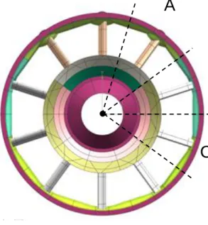
The weld producibility assessment system is developed against a jet engine turbine casing (Figure 1) as a starting point, considering the scalability to expand into all products. The goal for the system is to be applicable on any product at GKN.
Figure 1. CAD model of the component. Left: Isometric view. Right: Front view showing the different sectors.
Figure 1 shows the whole CAD model of the turbine casing and is referred to as a 360 model. The model is built using patterns of different sectors, as shown in the right side of Figure 1. This means that each sector is not unique, instead one sector can be repeated several times. In the model shown in Figure 1, there are three unique sections, mount (A), mount transition (B) and regular (C). The CAD models are created using sheet bodies and not solid bodies. The features (edges, faces, etc.) in the model are named using a strict naming convention, see Figure 2. The naming enables the user to know what each feature corresponds to in the physical component. For example, if a feature is a weld, surface, etc.
Figure 2. CAD feature name example.
1.1.3 PRODUCT DEVELOPMENT PROCESS
A
B
8
GKN uses the product development process shown in Figure 3 when developing new aero-engine parts. SBCE and the EWB tool (see next section) is used to create the design space and taper it. The EWB tool is used as support for the conceptual design and parameter studies. The aim is to include the weld producibility assessment as one of the parameter studies.
Figure 3. GKN product development process. (Stolt, et al., 2016)
1.1.4 EWB, EngineeringWorkbench
GKN Aerospace is constantly looking for new and improved ways and methods to use for improving their product development process. Currently GKN is using a software system known as EWB, a system that is tailored for, and developed by GKN Aerospace. EWB is developed to allow GKN to evaluate a wider design space without increasing the lead time.
EWB, short for engineering workbench, helps GKN to evaluate and optimize design concepts. The tool is used to generate data that allows the user to find relations between the design parameters the behavior/performance of the component, such as thermal, structural, aerodynamic and geometrical.
EWB works roughly as shown in Figure 4. The process includes four steps (excluding results). The first step is to create a CAD baseline, this is as the name suggests the baseline, or initial design concept. The baseline is created manually and works as a foundation from which the design variations, known as design cases, are generated. The definition of the design parameters in each design case is defined in the DOE. Example of design parameters controlled in the DOE are: number of struts, angle of the struts or diameter of the casing. Several parametric studies are then performed on each design case to determine the performance of that design. The results of the parameter studies are used to try and find relations between the design parameters and the product performance. These relations are later used to minimize the design space.
Figure 4. Rough structure of the EWB.
A major advantage with the EWB toolbox is its high level of automation. The automation not only allows GKN to evaluate more design parameters, it also allows for a higher variation for each parameter, creating a wider initial design
conceptual design Parameter studies in CAE Detailing and productin planing Physical test and verification Ready aero-engine BaselineCAD model DOE Design Cases
9
space. Currently EWB can analyze thermal, structural, aerodynamic and geometrical properties.
1.1.4.1 PRODUCIBILITY ASSESSMENT IN EWB
The weld producibility assessment is currently the least developed study in the EWB (compared to the other studies). As mentioned a prototype of a producibility system was developed and implemented at GKN by (Heikkinen & Müller, 2015). The prototype is built around using CAD models to provide the geometrical data for each design case. Based on the geometric data and user input the system generates process plans, suitable weld methods and a summary of the geometric data. The weld producibility assessment is implemented in the EWB but it is currently not used as a part of the parametric studies.
1.2 PURPOSE AND RESEARCH QUESTIONS
The purpose of the research is to re-design the current weld producibility assessment system at GKN. Increasing its flexibility and robustness to enable it to perform weld assessments on the varying design cases and to create a stable framework that can be further developed. The goal is to implement the assessment as a part of the EWB and the parametric study. GKN has yet to find the desired weld producibility system and since they continually want to improve their methods this opportunity should also be used to create more knowledge in this field. In this thesis two questions will be researched:
Q1. How can flexibility and robustness be introduced in a weld producibility
assessment system?
Q2. What tools, systems and software are required for the weld producibility
assessment system?
1.3 DELIMINATIONS
The research will include the development of a system for performing only weld producibility assessments. The system is to be developed at GKN and within their system. The system will be developed and evaluated against concept designs that is currently being developed at GKN
1.4 OUTLINE
Chapter 1, INTRODUCTION. Provides the reader with an introduction to the scope and background of the thesis
Chapter 2, THEORETICAL BACKGROUND. In this chapter the theoretical framework used in the thesis is explained. This mainly includes research and findings done by other people.
10
Chapter 3, METHOD. Here the scientific method used to conduct the work during the thesis is explained.
Chapter 4, PREPARING IMPLEMENTATION. This chapter includes a in-depth system and problem description, what various methods that are implemented to be able to develop the desired system and the initial structure of the system that was used to start develop the system. The chapter also includes the definition of three case studies, used to evaluate the system.
Chapter 5, RESULTS. In the results the final system is described in detail, how it is used and developed, what the final output of the system is, and where, and how, it can be used. The results of the three case studies are also presented. Chapter 6, DISCUSSION & CONCLUSION. In this chapter there will be a discussion regarding the used method, the final system and the case studies. This is followed by conclusions of the conducted work in regards to the research questions and suggestions for future work.
11
2 THEORETICAL BACKGROUND
This chapter introduces and motivates the theoretical framework used throughout the thesis.
2.1 KNOWLEDGE BASED ENGINEERING
Knowledge based engineering the usage of knowledge based systems in manufacturing and production, this obviously requires a knowledge-based system. In this thesis the definition of knowledge-based systems given by (Hopgood, 2001) is used.
2.1.1 KNOWLEDGE-BASED SYSTEMS
The main difference between “traditional” programming and knowledge-based systems is the structure. In traditional programming the knowledge is built in the application for manipulating that knowledge forming one “entity”. In KBS it’s the opposite. For the simplest case, the knowledge, also known as knowledge-base, and the application, known as interface engine are two separated entities. (Hopgood, 2001)
Figure 5. Main components of KBS adapted from(Hopgood, 2001).
The separation of the knowledge and the interface engine allows for easier maintenance of the knowledge, whether it is to add new knowledge or update existing knowledge. It also makes the system more accessible for the user. In traditional systems the user would need to go into the actual code to perform changes, usually requiring some programming skills. In the KBS the knowledge
12
is represented explicitly in the KB, not implicitly in the application and is therefore much easier to modify. (Hopgood, 2001)
2.1.2 KNOWLEDGE-BASE
The knowledge-base contains all the knowledge used by the system. The representation of the knowledge can be both simple and complex. The most common form of knowledge is rules and facts. (Hopgood, 2001)
// Fact Example. // <Property> = <Value> Length = 10 Thickness = 5 Curvature = 0.25 // Rule Example
// If <cause> Then <Effect>
If thickness > 5 then material is aluminium If Curvature > 0.25 then IsCurve is TRUE
13
2.2 MODULAR DESIGN IN SOFTWARE ENGINEERING
Modular design in software engineering is described by (Phillip A., 2007) as the breakdown of software functionality into encapsulated software elements. Modularity is achieved my grouping related elements, such as statements, procedures, variable declarations, object attributes, etc. (Phillip A., 2007) defines the main objectives of modularity “to foster high cohesion and low
coupling”.
2.3 MANUFACTURABILITY ANALYSIS SYSTEM
This thesis used the definition of manufacturability analysis systems given by (Shukor & Axinte, 2009). MAS was developed to make the transition from design to manufacturing more “natural”. Transitioning a concept design into a final product is traditionally done at the manufacturing phase of the product development. Where the manufacturing engineers decide if the concept can be manufactured or not. If the design can’t be manufactured its sent back to have the design reiterated. A problem with this is that the design engineers often don’t know specific manufacturing restriction, resulting in a design having to be iterated multiple times before transitioning into a final product. In order to try and avoid multiple iterations. (Shukor & Axinte, 2009)
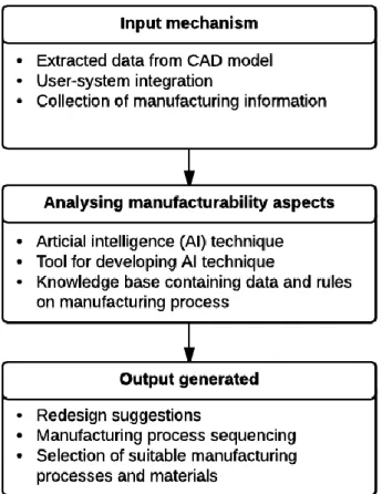
Manufacturability is a key part of the product development and being able to assess and analyse it at the design stage is very advantageous. It reduces the number of iterations needed, and in some cases remove the need to iterate all together. The MAS is developed around the usage of CAD/CAM systems to virtually check the manufacturability and with the goal to create a tool for computer aided design for manufacture (DFM) that can be implemented at early design stages. (Shukor & Axinte, 2009) proposes the following advantages of MAS:
The major advantage is to provide optional design changes that would remove manufacturing problems. The changes are based on a pre-defined Knowledge-base in the expert system.
Provide assistance when choosing manufacturing processes and materials based on predefined/built-in knowledge in the different aspects.
Suggest or assist in creating process plans for manufacturing the concept.
To enable the functionality above a knowledge-base needs to be defined, containing all the rules and facts about the different supported areas. Building and defining the KB as well as updating and maintaining it is a very important part of the MAS.
14
Figure 7. Basic methodology of MAS development (Shukor & Axinte, 2009).
2.4 EXPERT SYSTEMS
(Hopgood, 2001) defines expert systems as knowledge-based systems developed with expertise in a specific specialized domain. (Robert Alfred, et al., 1991) defines expert systems as computer programs that perform sophisticated tasks once thought possible only for human experts and mentions that KBS can be distinguished from other branches of artificial intelligence research by their emphasis on domain-specific knowledge, rather than more general
problem-solving strategies.
The system is intended to work as an expert in the field and provide the user with advice, recommendations and suggestions regarding the current problems. And expert systems should be able to describe and justify their decisions to make them more “acceptable” for the user (Hopgood, 2001).
2.5 DESIGN OF EXPERIMENT
Design of experiment is a method used to find and describe relations between the input parameters and the generated output of a process or system. A common DOE approach, as given by (Eriksson, 2008), is to define an interesting standard experiment and then perform new, representative experiments around it. (Eriksson, 2008) identifies two fundamental variables in DOE research, factors and responses.
15
Figure 8. (Eriksson, 2008)
Factors, or input, used to manipulate the system. Factors have a direct or in-direct influence on the responses of the system. Responses, on the other hand, provides information about the properties and state of the system. When evaluating a system, the system itself does not have to be known. The aim of DOE is to map what, and how, the factors influence the response. Not to define the system or process. (Eriksson, 2008)
2.6 TRANSPERANCY, FLEXIBILITY, TRACEBILITY &
ROBUSTNESS IN SOFTWARE ENGINEERING
(Yu-Cheng, 2014) mentions transparency as the meaning of making information visible to people and defines a working definition of transparency in software engineering as “the degree to which stakeholders can answer their
questions by using the information they obtain about a software system during its life cycle”. In this context stakeholders refer to anyone involved in the
development of a software system.
(Waman S, Ninth reprint 2008) refers to traceability as “facilities an
understanding of the effect on various functions and features, if modification is the requirement”. Further (Anon., 1990) defines traceability as: (1) “The degree to which a relationship can be established between two or more products of the development process, especially products having a predecessor successor or master-subordinate relationship to one another; for example, the degree to which the requirements and design of a given software component match.”
(2) “The degree to which each element in a software development product
establishes its reason for existing; for example, the degree to which each element in a bubble chart references the requirement that it satisfies.”
Robustness in software engineering refers to the ability to handle variation in data, without failing. (Anon., 1990) defines robustness as “The degree to which
16
or stressful environmental conditions”. (Waman S, Ninth reprint 2008) mentions “Software is considered robust if it reacts positively to a wide range of permissible and not permissible inputs and process conditions. In other words, if the software caters to permissible and non-permissible conditions and responds properly without any damage, then it is called robust”.
Flexibility is the ability to modify a system to meet new requirements. (Anon., 1990) defines flexibility as "The ease with which a system or component can be
modified for use in applications or environment other than those for which it was specifically designed.”. (McCall & McCall, 1977) refers to flexibility as “Extent of effort required to modify the software”.
2.7 SET-BASED CONCURRENT ENGINEERING
The set-based concurrent engineering, SBCE, methodology was invented by Toyota Motor Corporation. The reduction in lead time gained by implementing SBCE is a key factor for Toyotas success (Sobek, et al., 1999).
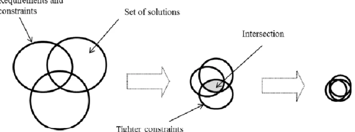
This thesis uses the SBCE definition given by (Sobek, et al., 1999). In SBCE multiple design solutions are created in parallel, using a set-based approach. As oppose to the traditional point-based approach. In the point-based approach only one “best” solution is selected. While in the set-based approach a range of feasible solutions are selected. “One key idea in set-based engineering is to
systematically build knowledge about multiple design concepts, based on additional information from development, testing etc., and then successively eliminate concept alternatives” (Johan, et al., 2013).
Figure 9. Sets, intersection and narrowing of sets. (Raudberget, 2012)
SBCE is not a strict methodology and follows three principles (Sobek, et al., 1999).
1. Map the design space. Define wide-ranging sets of solutions for each technical area.
17
2. Integrate by intersection. Each set of solutions is refined by removing solutions not feasible within other technical areas.
3. Establish feasibility before commitment. The feasible solutions are further refined by continuously increasing the level of detail in the solutions.
Another advantage of SBCE according to (Johan, et al., 2013). Is when developing new high end technology products, where knowledge about manufacturing solutions and producibility is very important. Through BSCE this knowledge can increase as the development progresses.
18
3 METHOD
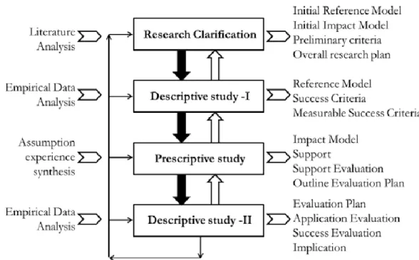
The selected method for this research is Design Research Methodology (DRM), developed by (Lucienee & Chakarbarti, 2009). The method proposes the research to follow the following steps:
• clarify what is meant by success [research clarification (RC) stage]; • understand relevant aspects of the phenomenon of design and its
influences on success [descriptive study I (DS-I) stage];
• based on this understanding, envisage what aspects of design can be improved and develop proposals, referred to as support, for improvement [prescriptive study (PS) stage];
• evaluate proposed support for its influence on success [descriptive study II (DS-II) stage];
• if the results are not acceptable, modify the support (go back to PS stage); and
• if still unacceptable, improve understanding of success and its links to relevant aspects of the phenomenon of design (go back to DS-I or RC stage).
19
3.1 RESEARCH CLARIFICATION
The aim of the research is to create a re-design of the current weld producibility assessment system with increased flexibility and robustness. The re-design is developed directly in EWB based on real cases.
To focus the research towards software engineering three common traits, according to (Boyd L, 2011), from the software development process will be adapted in the DRM.
Whatever process is implemented, make sure it involves developing in iterations (prescriptive study and descriptive study 2).
Be sure to incorporate a way to evaluate how well the process is working
(success criterions).
Incorporate approaches that will solve software issues and problems
(prescriptive study).
3.1.1 SUCCESS CRITERIA
The aim is to increase the flexibility and robustness of the system. Since the aim is to increase these factors the success will be measured by comparing the latest iteration with previous iteration. The data used for the comparison will be based of test-runs of the system. The test-runs will be carried out in pre-defined environments, based on the maturity of the system. Each environment is defined to require an increased flexibility and robustness than the previous. The system will be tested by performing an assessment on:
A. The CAD baseline in the design space.
B. Five design cases in the design space with one varying design parameter.
C. Five design cases in the design space with five varying design parameters.
D. Any number of design cases with any number of varying design parameters.
3.2 DESCRIPTIVE STUDY 1
A first descriptive study is carried out to capture the current state of the system, the environment in which it is used and provide knowledge about potential improvements based on previous research within the area. The study is performed by working with GKN’s current system to observe and analyse its condition. The study also includes getting familiar with other research done in the area, primarily the conclusions and findings of (Pabolu, 2015) and (Heikkinen & Müller, 2015). This study provides an understanding of the current
20
system, the connection with EWB, how it is used at GKN and potential factors that can influence the success criterion.
3.3 PERSCRIPTIVE STUDY
Based on the findings in the first descriptive study, assumptions and experience approaches for solving problems or improving the system in regards to the success criterion are defined. The improvements are then weighted based on the urgency of the improvement. Urgency is determined following these guidelines (in descending order, first is most urgent):
Is the improvement necessary for the system framework to work properly?
Is the improvement necessary for the system to be able to provide the desired output?
Is the improvement necessary neither necessary or provide output, but still desired?
3.4 DESCRIPTIVE STUDY 2
Only the most urgent improvements are implemented. More than one improvement can be implemented depending on the complexity and the estimated time it will take to implement. After implementation the improvement is evaluated in two steps. (Pabolu, 2015)
1. Could the proposed improvements be implemented in the current solution?
2. Did they improvements improve the success criteria?
Measuring the success criterions is done as described in section 3.1.1. The evaluation of the system is done by discussing the findings with my two supervisors and occasionally additional employees at GKN. Common questions during these discussions are:
• Could the system preform the desired assessment? If not, why was the system unable to perform the assessment?
• How much input variation can the system handle compared to previous iterations?
• If the system where to be applied to a different product, what changes to the system are required for it to work?
• If the system fails to perform an assessment, what information regarding why it failed does the user receive?
• Are there alternative solutions that can further increase the flexibility or robustness of any of the current solutions?
21
From the evaluation the current state/functionality of the system is defined. This is done to confirm that the development of the system is within the scope of the research. The system functionality is then compared with the system description to see if the system has reached the desired state. If not, the prescriptive study, descriptive study 2 and descriptive study 1 (if needed) is re-iterated until the system requirements are fulfilled.
22
4 PREPARING IMPLEMENTATION
This chapter covers the full system description, problem elaboration and the approach implemented to develop a flexible and robust system.
4.1 SYSTEM REQUIREMENTS
Based on the research questions, evaluation of the current prototype and discussion with my supervisor at GKN the following functional requirements where defined:
The ability to collect data from CAD models. This includes both data that can be accessed directly via native NX functions. E.g. curve length, curvature, thickness of a surface, etc. and custom data derived from the model.
Derive data that to estimate reachability from CAD models. Structure and summarize the collected CAD data.
Select the most suitable weld method for each weld in a design case based on user defined welding methods.
Generate process plans from the selected weld methods from user defined process plan templates.
High user customization. The user should be able to tailor the assessment according to their need through different input parameters. Automated system. Only the input should be defined by the user. All
other system operations should be automated. Export results in a structured format.
Function on a non-strict, varying geometry.
The aim is to increase the flexibility and robustness of the defined functionality without compromising other key aspects of the system. Such as transparency, scalability, recognisability and traceability (Graziotin, et al., 2014) (Pabolu, 2015) (Leite & Cappelli, 2010). With that in mind the following system requirements was defined.
The system should be flexible and robust (upgradability, flexibility, robustness). Even if the system is evaluated for only one product, the long-term goal is to be able to apply it on a wider range of products and concept studies (scalability). A well-structured system architecture is required for the dependency and relations between functions to be clear (traceability) and to enable easier further development. Be it to implement new functionality, update the current functions or adapt the system to new products.
23
The system should be intuitive (transparency, traceability and recognisability). It should be easy to use and understand, and provide a clear and well documented result (transparency). It is very important for the validity of the result that the process used in the weld assessment system is understood by the user (recognisability), as understanding the system increases the validity of the results. It is equally important that the assessment definition is clear and user friendly. It should be made clear for the user how the assessment is defined and what type of results the assessment will generate (traceability).
GKN use both Windows and Linux and the system aims toward being functional on both platforms (flexibility).
Software/system integration is a requirement. To enable a functional, robust and flexible integration a clear structure is used. This allows for both easier maintenance and the addition of new software (upgradability).
4.1.1 PROBLEM ELABORATION
System Integration. System/software integration is necessary for the weld producibility assessment system since multiple software are needed to perform the full assessment. Achieving seamless and robust integration can be problematic due to several factors. (1) Not all software can be integrated with all programming languages. (2) Transportation of data and different data structures. Programing scripts often only accepts raw text as input/output and objects cannot be communicated between software.
System Architecture, Flexibility and Robustness. There is always a strive for increased flexibility and robustness, for obvious reasons. In addition, the aim for the developed system is to be usable in other similar applications, handle a “any” CAD geometry and ease of upgrade. This requires that the system has no, or close to no restrictions on what geometry it can assess and that the entire system can adapt to the current CAD data and the user input. To develop a system architecture that fulfills these requirements is the main challenge of the thesis.
4.2 IMPLEMENTATION
This section explains the general thought behind the approach used to overcome the major issues and how the system is developed to increase its flexibility and robustness.
4.2.1 SYSTEM INTEGRATION
It is common for software and systems to have an API (application programming interface). The API is used to access software functionality remotely and is done
24
by importing a software library to the application. The API can be utilized to create knowledge objects. Knowledge objects is a class that takes input parameters and turn them into output through a certain external method or software. Knowledge objects is also used to create script that runs pre-defined operations (Johansson, 2011). The API is also used to execute a program in batch mode, also known as batch processing. This is a very powerful and convenient way of integrating software in automated systems as it is non-interactive and instead all input parameters and what software operations that is performed is predefined within the system.
The CAD software has to be integrated in the weld producibility assessment system to extract the geometric data for each design. The CAD software used at GKN is Siemens NX and it offers multiple solutions for integration. The prototype system includes a working integration of NX exists in the prototype. The integration is done by executing a VB script that starts NX, opens the correct model and extracts the data by adding and evaluating knowledge-fusion rules. This method is referred to as “journaling” in NX. The aim is to try and re-use this solution and refine the functionality.
(Pabolu, 2015) system is developed using a framework of CATIA, MS-Excel and specially developed software called “Howtomation”. At GKN they don’t use CATIA or Howtomation so this approach can’t be completely re-used. The prototype also uses Excel to store all data and it will be used in the re-design as well.
4.2.2 SYSTEM ARCHITECTURE
The system re-design will use a modular design approach. On a top-level the system will be divided into “core” modules, where each module represents a major functional area within the system. Each of these modules should be separate and have no direct connection. Each module should only be dependent on its required input data to function. This data that will be generated by other modules creating an indirect dependency.
Each core module will also implement a modular design. This will allow each core module to include several modules for performing the same operation using different input to expand the data variation the system can handle, increasing flexibility and robustness.
An upside with modules are that the user can execute the same module several times without executing the other modules. In the weld producibility assessment this can be used to assess the same CAD data any number of times, each time with a different input, providing different results.
25
Even if this system is focused on the weld producibility of one component, the long-term goal is to be able to perform a weld assessment on any product at GKN. Using a modular structure increases the flexibility of the system making it easier to further develop and expand. Since the modules are independent they don’t have to be taken into consideration when developing new modules. But can of course be re-used if it fits the purpose.
4.2.3 ROBUSTNESS AND FLEXIBILITY (TRANSPARENCY,
SCALABILITY, RECOGNISABILITY AND TRACEABILITY)
In this system robustness refers to the ability to handle input variation (user and CAD) within the specified application without failing and flexibility as the ability to further develop, modify and expand the system. An increase in flexibility and robustness will be achieved implementing a knowledge-based with autonomous knowledge and an interface engine. This way knowledge can be added, removed or modified without disrupting the operation of the system (Johansson, 2011). All facts and rules in the knowledge-base will be derived from the user input and extracted CAD data. The aim is that no data should be considered as “wrong” and that the interface engine will adapt to the available knowledge. However, certain combinations, or lack of knowledge will cause the system to fail. Exactly what cases that will cause system failure is very hard to foresee. Instead the system always tries to execute with the provided input and provides the user with constant feedback of the process.
From a user point-of-view flexibility is directly connected to the robustness of the system. The aim is to include as few as possible restrictions on the user input by allowing the user to define all system inputs. This will allow the user specify the assessment after current needs and will only be restricted by the robustness of the system.
Transparency and recognisability is implemented to clarify to the user what is being assessed and how. This is a direct effect of the implementation the robustness and flexibility. Since all the data used by the system is defined by the user, except for CAD data, the user can always review the input for the assessment definition. As previously mentioned the modular architecture will increase the systems traceability and scalability. An increase in traceability is an effect of the well-defined structure, making it easier to find the source of a problem. Increased scalability is a direct effect of the modular approach, where modules can be added, removed and modified with ease.
4.3 PRINCIPAL SYSTEM STRUCTURE
The new architecture works towards increased robustness and flexibility of the system. This is achieved by applying the methods described in this and previous chapters. done by removing function dependencies, generalizing
26
functions and framework, implementing a modular structure, knowledge-base, provide the user with feedback of the process, etc.
The architectures used by (Pabolu, 2015) and (Heikkinen & Müller, 2015) is shown in and Figure 12.
27
Figure 12. Weld producibility system. (Pabolu, 2015)
Figure 13 shows principal system architecture with each module being numbered and the software required in parenthesis. The architecture is built using three modules.
1. Module for handling and defining the user input (assessment definition). 2. Module for collecting all necessary data from NX (collect CAD data). 3. Module for analyzing the data and providing the system output (data
evaluation).
Each module has multiple child functions and/or modules to enable the parent module’s function. The overall architecture is derived from architecture used in (Heikkinen & Müller, 2015) and (Pabolu, 2015) systems. Note that this is not the final architecture. It’s the initial architecture that was used to start developing the system and the final solution has a slightly different architecture.
The purposed architecture is much like that in Figure 7, section 2.2 and include the necessary parts for a manufacturing assessment system. The architecture allows for a high level of automation since only the assessment definition requires user interaction. Separating, avoiding dependency and modularizing the functionality and input should make the system more robust and increase the flexibility. For the user to be able to freely define weld methods, process plans and scope for each assessment will increase the flexibility.
28
Figure 13. Principal system architecture.
4.3.1 ASSESSMENT DEFINITION.
Module 1, Assessment Definition, contains the necessary functions for the user to define the assessment. The input of the system will include three different files containing:
CAD definition. What design cases are to be assessed? And what parts of the model are to be included?
Weld methods. The weld methods are defined by the user to increase the flexibility of the system. They are also necessary if the system is to find the best suited weld methods for the design.
Process plan templates. User defined to provide increased user flexibility and necessary to create process plans.
29
Figure 14. Purposed assessment input structure.
The weld methods and process plan templates are defined completely by the user and should be done with as few restrictions as possible. The aim is to give complete freedom to the user when defining the assessment, increasing the user flexibility. The weld methods are implemented in the knowledge-base as rules and the process plan is created based on the selected weld methods. It should be possible to do the CAD definition from within NX to make it more intuitive for the user. The CAD definition should go in-line with the other input and have close to no restrictions.
Figure 14 shows the purposed architecture for this module. Each input module is made independent by removing their direct dependency and allowing each to be defined separately. While this might decrease the transparency it will allow for each input to be defined simultaneous. Removing the direct dependency between the input also means that the user may choose any combination of the three input files, using previously and/or newly created input files as input for the system.
4.3.2 COLLECT CAD DATA
The “Collect CAD data” module extracts all necessary CAD data and adds it to the assessment input. The module should require no user interaction and the functionality is based on the same method used in the prototype (section 4.2.1). The required operations should be clearly separated and avoid dependency between each other. Figure 15 shows the purposed architecture. The module requires the CAD model and CAD definition. In Figure 15. Proposed structure for collecting data from NX.only three types of data extractions are included to
30
show the principal architecture, the final module will include length, curvature, thickness, material id and reachability. All the extracted data is stored both individually and gathered in one location for easier access. This data is used to provide the knowledge-base with its facts. The should also be stored outside of the assessment so that it can be accessed and re-used in other assessments.
Figure 15. Proposed structure for collecting data from NX.
4.3.3 DATA (WELD) EVALUATION
The data evaluation module will, as the name suggests, perform the actual evaluation and provide the user with the result. This is the systems most extensive, complex and important module and where the implementation of flexibility and robustness is of foremost importance. Figure 16 shows the principal architecture of the evaluation module. The evaluation will be developed in python so that it can be executed on both windows and Linux. As mentioned the knowledge-base is created using the assessment input (CAD data = facts, weld methods = rules) and evaluated by the interface engine. The interface engine has the same modular approach as the rest of the system and each evaluation has to be pre-defined in the interface engine. The output is then either returned directly by the evaluation functions, or summarized and then returned. This approach and architecture will increase the flexibility and
31
robustness of the system. The knowledge-base allows the evaluation to adapt to the input and perform assessments on potentially any CAD geometry.
Figure 16. Proposed structure for analyse.
4.4 CASE STUDIES
The system will be evaluated using three case studies. The case studies are used to primarily evaluate the performance of the system and to test its flexibility and robustness.
The case studies are defined to evaluate the welds in the strut of a mount sector, used for connecting the inner and outer hub of the casing. For the case studies a concept design like that in Figure 1 is used. Each study will evaluate 48 design cases, all with unique design parameters. The three studies are defined to assess three different manufacturing concepts.
32
Figure 17. Section definition for case study. From left to right, Case A, Case B and Case C.
The aim for the studies is that the system should perform the three different assessments without failure.
Figure 17 shows the weld definition on the strut for the three cases. The blue line represents the position of a weld and the green dotted line the “new” sections of the strut. Case A will evaluate a strut with one section, welded at the rear. Case B a strut with three sections with two welds at the front and one at the rear. Case C a strut with two sections, welded at the front and rear. The manufacturing input for all the three cases are the same. The input used for the design cases can be found in appendix A. Note that all values do not represent “real” values and that the same process plan is used for all weld methods.
33
5 RESULTS
In this chapter the final system will be explained in detail, including both the overall structure as well as the usage and development of each individual module. Followed by a summary of the system output and the result of the three case studies.
34
5.1 WELD PRODUCIBILITY ASSESSMENT SYSTEM
ARCHITECTURE
To provide a better understand of how the system works the overall architecture of the system is briefly described followed by a detailed explanation of each module, covering functionality, usage, development and why it’s required.
Figure 19. System architecture overview.
The system is built to perform a weld producibility assessment on 3D CAD models. The system uses the CAD geometry in combination with weld producibility data to derive the weld producibility of a design concept. An overview of the system architecture is shown in Figure 19 and the complete architecture is shown in Figure 18. The architecture is a refined version of the structure purposed in section 4.3 and is composed of three core modules. (1) assessment definition, (2) collect CAD data and (3) data evaluation. Figure 19 shows dependency, data flow and software used for each system operation. Each module core module only depends and require the correct input data and no “direct” connections between the modules exist. The whole assessment is defined in the “assessment definition” module. This is where the user defines the features to include in the assessment, the weld methods and the process plan templates. The feature definition is then used to collect the right CAD data, which in turn is used together with weld methods and process plan templates to define the knowledge-base for the data evaluation.
35
ASSESSMENT DEFINITION
The final system requires three different input files, all stored in excel, as seen in Figure 20.
1. Assessment definition. The assessment definition includes feature selection, the preferred weld methods and what data the summary should include (data keywords).
2. Weld methods. The definition of the weld methods used by the system defined manually in excel.
3. Process plan templates. The process plan templates used by the system defined manually in excel.
Defining a new assessment is either done using existing input files, creating new input files or by mixing new and existing input files. This is made possible since none of the input files have any direct connection to one another and can therefore be used in any combination.
Figure 20. Final structure of the assessment definition.
COLLECT CAD DATA
The system can collect length, curvature, thickness, material id, reachability distance and reachability angle from CAD models. Figure 21 shows the
modular architecture for this module. Each function used to collect data works independent to ease adding, removing or modifying what data to collect.
36
Figure 21. Collect CAD data architecture.
DATA ANALYSIS
The architecture used when evaluating the data is shown in Figure 22. The evaluation is done by first importing and structuring the assessment input to create the knowledge-base. The interface engine then uses the knowledge in the knowledge-base to adapt to the current knowledge and perform the evaluation. This allows the system to evaluate a wide variety of data, increasing its flexibility and robustness. The system performs three different evaluations.
37
1. Summary of CAD data. This primarily includes min/max values of the collected CAD data and a summary of the weld method selection. 2. Weld method selection. Based on the defined weld methods the system
finds the best suited methods for each selected feature.
3. Process plan generation. Process plans are generated from the weld method selection
Figure 22. Final structure of the data analysis.
5.2 ASSESSMENT DEFINITION MODULE
The assessment definition module handles all the user input for the system. Here the user defines what part of the CAD model that should be evaluated, what manufacturing data that should be used for the evaluation and what data the system should return. As mentioned the input consists of three files, feature selection, weld methods and process plan templates.
All input files are created and stored in excel using predefined templates, one for each input file. Excel is used because it provides a structured data format, its frequently used in the EWB and since a very common software that a lot of people are comfortable with.
38
Figure 23. Feature selection input file example.
5.2.1 ASSESSMENT DEFINITION INPUT
As shown in Figure 24 the assessment definition input-file includes three parts, the feature selection, the data keywords and the preferred weld methods. The assessment definition is defined in one Excel workbook with each part on a separate sheet.
Figure 24. Assessment definition structure.
5.2.1.1 FEATURE SELECTION
Figure 23. Feature selection input file example.Figure 23 shows an example of the feature selection in the assessment definition. The feature selection includes all the “weld features” that is to be included in the assessment. A weld feature is a feature in NX (always an edge) that represents a weld in the component. In Figure 23 each row represents one weld feature and each column one of four selectable attributes. The attributes, constraining object, group and order are used to further customize and specify the feature selection, the description of each attribute is done in section 5.2.1.2.
Selecting the weld features and defining their attributes is done by the user, who has three ways of doing this. Manually, via Python script or an NX
39
application. The system requires at least one defined weld feature to be able to perform the evaluation (it can’t evaluate nothing).
1. Manually. The system doesn’t require the input to be defined using any special software or method, which means that the template can be filled out by hand. However, this is not recommended. For the input file to work all the names of the weld features has to be correct and doing this manually tends to be very time consuming. One advantage with being able to directly access and modify the input file is that it allows the user to copy and paste selections from other input files without having to redo the whole selection.
2. Python Script. The python script is intended for one use only, to get all weld features in a given CAD model. The script doesn’t add any attributes to the weld features, just exports the feature names to the Excel file.
3. Custom NX Application. The most convenient and user-friendly way of defining the weld features input is to use an NX application developed in this thesis for this exact purpose. The application allows the user to directly select weld features from the CAD model and export them to the Excel template. For a more detailed description of how the application works, how it’s used and how it was developed see section 5.2.2.
As mentioned in the introduction the design cases are generated from a CAD baseline. It’s recommended to use this baseline when selecting the weld features. This can be done from either a 360- or a sector- model (see Figure 1) of the design, depending on what the user wants to evaluate.
Unfortunately, there is currently some problems with running the geometry evaluation on the 360 model. This is due to the current naming of some features in the part, which include duplicate names. The geometry analysis can still be ran on the 360 model, but there is a chance that the result is wrong. So for now it is recommended to perform the assessment of sector models.
5.2.1.2 WELD FEATURE ATTRIBUTES
CONSTRAINING OBJECT
The constraining object attribute is a list of surfaces that the system uses and requires to derive the reachability data (see Figure 23). The constraining object(s) corresponds to the surfaces that will exist in the component when welding that edge. The CAD model contains the entire finished geometry and during manufacturing the geometry is sequentially built. Therefor the system need to know what surfaces are present in what sequences. The constraining objects can also be viewed as the surfaces that potentially can restrict the
40
movement of the welding robot during welding. How the constraining objects are implemented when deriving the reachability data is covered in section 5.2.3. The user can select any combination of surfaces in the CAD model the to be used as constraining objects. This provides the user with an increased flexibility when defining the feature selection and it allows the user to set-up different manufacturing sequences.
The best, fastest and most convenient way of selecting constraining objects is by using the NX application described in 5.2.2.
GROUP
The group attribute allows the user to group any selection weld features by specifying a group, either by name or number (see Figure 23). Grouping weld features tells the system that the grouped welds should be viewed as one weld. The user can add a group to the weld features either manually or via the NX application.
Utilizing the grouping allows the used to further specify weld sequences, increasing the flexibility of the system. Both real and experimental sequences can be defined to see how it effects the producibility. For an example on how the grouping can be used see section 4.4.
ORDER
The order attribute is added manually in excel and decides the order in which he output data is structured, most importantly the process plan. This attribute has no direct effect on the data is evaluated and only effect the order of the output data. The order is added manually.
41
Figure 25. Available data keywords.
5.2.1.3 DATA KEYWORDS AND PERFFERED WELD METHODS
The data keywords are a list of strings, referred to as keywords, that tells the system what data it should include in the summary. Each keyword represents different data and all available keywords and the data they refer to is shown in Figure 25. The user defines what keywords to use by simply adding the desired keywords to a list.
The preferred weld methods are a numbered list defining which weld methods that are preferred. This is used as a part of the evaluation to decide the best suitable weld methods. Both the data keywords and preferred weld methods is defined manually.
5.2.2 NX APPLICATION
An application in NX was developed to make it easier for the user to select the weld features for the feature selection input. This includes the selection of weld features, constraining objects and groups.
42
USAGE
The application allows the user to fill out the Excel template directly from NX by selecting the wanted features from the CAD model.
Too add weld features through the application (Figure 26) the user first selects the features in the model. The user can then choose to either add the selected features to Excel and reset the selection, or to add the features to Excel and copy the feature selection to the constraining object section.
Since the constraining objects and group is a feature attribute the user needs to select what feature the attribute should be added to and the value of the attribute. The way the application works is that in order to add constraining objects or group to a feature, the feature needs to be listed in excel. This also means that the application can be used to modify already existing feature selection files.
43
DEVELOPMENT
The NX application is created as an extension of the user interface in NX and is developed solely in KF by using the built in UI classes and custom rules. The application is coded in one KF script that includes both the definition and functionality of the UI.
Constructing a UI in KF is done by combining built-in UI elements (UI classes) to create the desired layout. Each UI element is defined by creating a new instance of a UI class and adding it as a child object to the main KF rule. For example:
// ui class example. // example button.
// define that the object is a child, and its name.
Child Button {
// define the type of ui element by defining the class.
Class, ui_button
// each ui class has different properties.
// For a button it’s enough to specify the text on the // button.
Text, “a button” }
// Example label. Child Label
{
Class, ui_label
Text, “this is a label” }
The example above would create a button (as seen in Figure 26) with the text “a button” and a label with the text “this is a label”. Each UI classes inherits several general properties from the ui_class in combination with unique properties for that specific ui_class. There are also several UI classes that is used only for containing and structuring the UI layout, e.g.
// group example.
Child Group_A {
Class, ui_group
// the child object that are included in the group.
Members, {Button, Label, ...} }
44
Child Group_B {
Class, ui_group
Members, {Button_B, Label_B, ...} }
Child Tab_Group {
Class, ui_tab_group
Members, {Group_A, Group_B} }
The ui_group class will group all elements declared under members in the order they are written and the ui_tab_group class will create a new tab with the elements defined under members (see Figure 27). Creating a UI in KF requires each element to be defined separately, then structured using the specific classes.
Figure 27. Containers used in the NX application.
TAB GROUP
OPEN UI GROUP
CLOSED UI GROUP
45
The functionality of the application is very straight forward. What the application does is simply to write the name of the selected features, constraining object or group to Excel. KF has native functions for reading and writing to excel, making the functionality easier to develop.
When adding weld features the script opens the specified feature selection Excel-file, looks for the first empty cell in the weld feature column and adds the selection from that cell and onwards.
// write to excel example. {
// open excel and the correct worksheet.
Excel_app = excel.open(workbook)
Excel_sheet = Excel_app.sheet(some sheet)
// read the name column from excel. The function will // unity there are no more values in the column.
Names_in_excel = Excel_sheet.read(feature name column)
// the start row is equal to the number of rows read.
Start_row = length(names_in_excel)
// define the range in excel to write the names to. // the range is defined to be the feature name column // from the start row and onwards.
Range = {
feature name column, Feature name column, Start_row,
:}
// write the selected features to the range.
Excel_sheet.write(selected feature, range) }
When adding the constraining object and group the application has to find the row corresponding to the feature that the attributes should be added to. The constraining objects or group is than added to that row. In KF it’s solved as follows.
// write constraining object or group to excel.
{
Excel_app = excel.open(workbook)
Excel_sheet = excel_app.sheet(some sheet)
Names_in_excel = excel_sheet.read(name column)
// loop through each selected feature.
46 {
// get the position of the feature name from the list // with all names from excel.
Index = find(feature.name, names_in_excel) Range = {
feature name column, Feature name column, index,
index}
excel_sheet.Write(constraining objects/group, range) }
}
The problem with this code, or rather the way the function for finding an item in a list works, is that it only finds the first occurrence. So if a feature name appears on multiple rows the script will only write the constraining objects or group to the first occurrence.
In order be able to connect the functions with the UI KF uses a built-in “update” function. This function is called each time the user interacts with any UI element, with the active UI element as input (instance).
// ui update example
{
// the instance is set to the active ui element.
Instance = INSTANCE
// the functions check what ui element it is using an // if statement.
If instance = some ui element {
//Do stuff }
Else if instance = other ui element {
//Do some other stuff }
}
5.2.2.1 MANUFACTURING INPUT, WELD METHODS & PROCESS PLAN As mentioned the system requires manufacturing data to be able to perform the assessment. The manufacturing required for the assessment is as mentioned weld methods and process plan templates. The weld methods are used as the rules of the knowledge-base and having the option to freely define and modify this input for each assessment allows for further customization and flexibility.