M¨alardalen University Press Licentiate Theses
No.52
Modeling the Temporal
Behavior of Complex
Embedded Systems
A Reverse Engineering Approach
Johan Andersson
June 2005
Department of Computer Science and Engineering
M¨alardalen University
Printed by Arkitektkopia, V¨aster˚as, Sweden Distribution: M¨alardalen University Press
Abstract
Software systems embedded in complex products such as cars, telecom sys-tems and industrial robots are typically very large, containing millions of lines of code, and have been developed by hundreds of engineers over many years. We refer to such software systems as complex embedded systems.
When maintaining such systems it is difficult to predict how changes may impact the system behavior, due to the complexity. This is especially true for the temporal properties of the system, e.g. response times, since the temporal behavior is dependent on many factors that are not visible in the implemen-tation, such as execution time. The state-of-the-practice is therefore often the trial-and-error approach, i.e. implement and test. However, errors related to the temporal behavior are often hard to find while testing the system and may cause major economic losses if they occur post-release, since they typically result in system failures.
This thesis presents a method for predicting these types of errors in an early stage of development. The specific method proposed is called behavior impact analysis, which aims to predict if a specific change to the system may result in errors related to the temporal behavior. The method especially targets complex embedded systems and by using this analysis method in the software development process, the number of errors introduced when maintaining the system can be reduced. This results in an increased productivity in maintenance as well as an improvement in system reliability.
This thesis focuses on the construction and validation of the temporal be-havior model necessary for performing a bebe-havior impact analysis. The con-clusion of the thesis is that a combination of dynamic analysis and reverse en-gineering is suitable for modeling the temporal behavior of complex embedded systems. Regarding validation of temporal behavior models, the thesis propose a process containing five increasingly demanding tests of model validity. Tools are presented that support the model construction and validation processes.
Preface
This work has been supported by ABB Robotics and ASTEC, the VINNOVA competence center on software technology, as well as ARTES and SAVE-IT.
I would like to thank my supervisors, Professor Christer Norstr¨om, Dr. Anders Wall and Professor Bj¨orn Lisper, for their enthusiasm and excellent support during these years! Thank you! Also Professor Hans Hansson and Joel Huselius has taken the time to read and comment this thesis, thank you!
Peter Eriksson has provided a lot of valuable input and comments on this research from ABB Robotics point of view. Our interesting discussions have given me a much better understanding of the industrial robotics domain and ABB’s robot control system. Your enthusiasm and positive spirit have been very supportive! Thank you!
I would like to thank Professor Wang Yi, Professor Bengt Jonsson, Pavel Krcal, Leonid Mokrushin and Xiaochun Shi, Uppsala University, for many interesting discussions! I would also like to thank all my colleagues at the department, especially Joel Huselius, Jonas Neander, Johan Fredriksson, Dag Nystr¨om, Thomas Nolte, Daniel Sundmark, Anders Pettersson, Joakim Fr¨oberg and Jukka M¨aki-Turja, for the many laughs and interesting discussions!
I want to direct many thanks to my friends Christian Hultman, Christian Andersson, Klas Andersson and Rickard S¨oderb¨ack, for a total of 40 years of friendship. Finally I want to express my gratitude to my fianc´e Birgitta, my parents Lennart and Susanne, and my sisters Josefin and Jessica, for your love, support and interest in my work.
Thank you all!
Johan Andersson V¨aster˚as, June, 2005
Publications
The author of this thesis has authored or co-authored the following publica-tions:
Articles in collection
A Dependable Open Platform for Industrial Robotics - A Case Study, Goran
Mustapic, Johan Andersson, Christer Norstr¨om, Anders Wall, Architecting Dependable Systems II, Lecture Notes in Computer Science (LNCS) 3069, Editors: Rogrio de Lemos, Cristina Gacek, Alexander Romanovsky, ISBN: 3-540-23168-4, 2004.
Conferences and workshops
Model Synthesis for Real-Time Systems, Joel G Huselius, Johan Andersson, In
Proceedings of the 9:th European Conference on Software Maintenance and Reengineering (CSMR ’05), p 52-60, Manchester, UK, March, 2005
Decreasing Maintenance Costs by Introducing Formal Analysis of Real-Time Behavior in Industrial Settings, Johan Andersson, Anders Wall, Christer Norstr¨om,
In Proceedings of the 1st International Symposium on Leveraging Applications of Formal Methods (ISoLA ’04), Paphos, Cyprus, October, 2004
Validating Temporal Behavior Models of Complex Real-Time Systems, Johan
Andersson, Anders Wall, Christer Norstr¨om, In Proceedings of the 4th Confer-ence on Software Engineering Research and Practice in Sweden (SERPS’04), Link ¨oping, Sweden, September, 2004
Real World Influences on Software Architecture - Interviews with Industrial Experts, Goran Mustapic, Anders Wall, Christer Norstr¨om, Ivica Crnkovic,
Kristian Sandstr¨om, Joakim Fr¨oberg, Johan Andersson, In Proceedings of the 4th IEEE Working Conference on Software Architectures (WICSA ’04), Oslo, Norway, June, 2004
Correctness Criteria for Models Validation A Philosophical Perspective, Ijeoma
Sandra Irobi, Johan Andersson, Anders Wall, In Proceedings of the Inter-national Multiconferences in Computer Science and Computer Engineering (MSV ’04), Las Vegas, June, 2004
Increasing Maintainability in Complex Industrial Real-Time Systems by Em-ploying a Non-Intrusive Method, Christer Norstr¨om, Anders Wall, Johan
An-dersson, Kristian Sandstr¨om, In Proceedings of the Workshop on Migration and Evolvability of Long-life Software Systems (MELLS ’03), Erfurt, Ger-many, September, 2003
Probabilistic Simulation-based Analysis of Complex Real-Times Systems,
An-ders Wall, Johan AnAn-dersson, Christer Norstr¨om, In Proceedings of the 6th IEEE International Symposium on Object-oriented Real-time distributed Computing, IEEE Computer Society, Hakodate, Hokkaido, Japan, May, 2003
A Dependable Real-Time Platform for Industrial Robotics, Goran Mustapic,
Johan Andersson, Christer Norstr¨om, In Proceedings of the ICSE 2003 Work-shop on Software Architectures for Dependable Systems (ICSE WADS), Port-land, OR USA, May, 2003
Introducing Temporal Analyzability Late in the Lifecycle of Complex Real-Time Systems, Anders Wall, Johan Andersson, Jonas Neander, Christer Norstr¨om,
Martin Lembke, In Proceedings of the 9th International ConferenceR on eal-Time and Embedded Computing Systems and Applications (RTCSA ’03), Tainan, Taiwan, February, 2003
Technical reports
Influences between Software Architecture and its Environment in Industrial Systems a Case Study, Goran Mustapic, Anders Wall, Christer Norstr¨om, Ivica
ix
Crnkovic, Kristian Sandstr¨om, Joakim Fr¨oberg, Johan Andersson, MRTC re-port ISSN 1404-3041 ISRN MDH-MRTC-164/2004-1-SE, M¨alardalen Real-Time Research Centre, M¨alardalen University, February, 2004
A Framework for Analysis of Timing and Resource Utilization Targeting Indus-trial Real-Time Systems, Johan Andersson, Anders Wall, Christer Norstr¨om,
Contents
1 Introduction 1 1.1 Our Approach . . . 6 1.2 Research Questions . . . 8 1.3 Research Approach . . . 8 1.4 Contribution . . . 9 1.5 Thesis Outline . . . 102 Temporal Behavior Modeling and Analysis 13 2.1 Reverse Engineering . . . 15
2.1.1 Tools for Structural Analysis . . . 15
2.1.2 Tools for Behavior Analysis . . . 17
2.2 Model Validation . . . 21
2.3 Real-Time Systems . . . 24
2.3.1 Analytical Response-Time Analysis . . . 26
2.3.2 Simulation based Analysis . . . 26
2.3.3 Execution Time Analysis . . . 28
2.4 Model checking . . . 29
2.4.1 Basic Concepts . . . 29
2.4.2 The model checker SPIN . . . 30
2.4.3 Model checking Real-time Systems . . . 33
2.5 Discussion . . . 36
2.5.1 Modeling . . . 36
2.5.2 Analysis . . . 37
3 Dynamic Analysis 39 3.1 Uses of Dynamic Analysis . . . 40
3.1.1 System Understanding . . . 41
3.1.2 Modeling System Behavior . . . 41
3.1.3 Regression Analysis . . . 41
3.2 Recording – What, How and Costs . . . 42
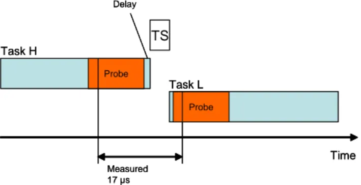
3.2.1 The Probe Effect . . . 45
3.2.2 Relevant code instrumentation . . . 46
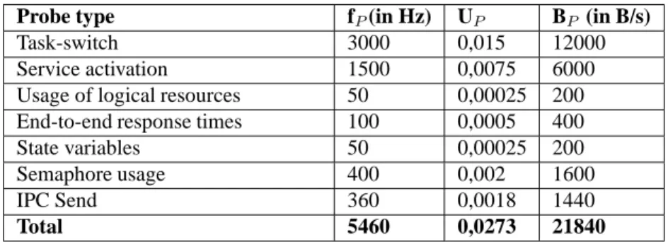
3.2.3 Resource Consumption . . . 49
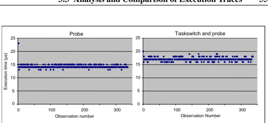
3.2.4 Implementation and Evaluation of a Behavior Recorder 51 3.3 Analysis and Comparison of Execution Traces . . . 55
3.3.1 The Probabilistic Property Language . . . 57
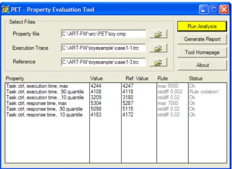
3.3.2 The Property Evaluation Tool . . . 62
3.3.3 The Tracealyzer . . . 64
3.4 Discussion . . . 67
4 Modeling Temporal Behavior 69 4.1 Behavior Impact Analysis . . . 72
4.2 Modeling System Behavior . . . 75
4.2.1 The Modeling Process . . . 76
4.2.2 The Model Specification . . . 77
4.2.3 The Functional Model . . . 78
4.2.4 The Model Parameters . . . 81
4.2.5 Identification of Dependencies . . . 88
4.3 Modeling the Environment . . . 89
4.3.1 Identification and Classification of stimuli . . . 90
4.3.2 Modeling Approaches for Environment Models . . . . 92
4.4 Discussion . . . 94
5 Model Validity 95 5.1 Validity Threats . . . 97
5.2 A Model Validation Process . . . 99
5.2.1 The Trace Comparison Test . . . 101
5.2.2 The Property Comparison Test . . . 103
5.2.3 The Analysis Variability Test . . . 105
5.3 Observable Property Equivalence . . . 106
5.3.1 Comparing Behavior . . . 107
5.3.2 Observable Property Equivalence – A Formal Definition 108 5.3.3 Selecting Comparison Properties . . . 109
5.4 Model Robustness . . . 112
5.4.1 Sensitivity Analysis . . . 113
Contents xiii
6 Conclusions 119
6.1 Future Work . . . 121
6.1.1 Automated modeling . . . 122
6.1.2 Alternative Analysis Methods . . . 123
6.1.3 Regression Analysis Case Study . . . 123
A ART-ML 2.0 125
B PPL Implementation 135
C An example model specification 139
Chapter 1
Introduction
As computers have become more powerful and less expensive they have be-come a common and natural part of our everyday life. However, most com-puters manufactured today are not desktop comcom-puters, but embedded in prod-ucts such as mobile phones, microwave ovens, refrigerators, toys, cars, trains, airplanes and many different types of audio and video equipment. Product developing companies have replaced electrical and mechanical solutions in their products with embedded computers. Computer-based solutions are less expensive, require less space and power and also allows for more advanced functionality. Embedded computers come in all sizes, from very small and simple 8-bit single-chip computers, with a few kilobytes of memory, to giga-hertz 32-bit computers with vast resources. This thesis focuses on embedded computer systems of the latter category, large software systems embedded in complex products such as industrial robot control systems, automotive systems and telecommunication systems. Systems of this type often contain millions of lines of code and have been developed by hundreds of engineers over many years. Such systems are too large and complex for any single person to un-derstand in detail. In this thesis, we refer to such software systems as complex
embedded systems.
Common characteristics of complex embedded systems are their safety critical and/or business-critical nature. Typically, systems of this class are in control of machinery and therefore have requirements on dependability, such as safety, reliability and availability. Moreover, the majority of systems of this class are real-time systems, i.e. systems that must respond to input from its environment in a timely manner. For non-real-time computers such as home
PC’s, CAD-workstations or game consoles, the focus is on the average perfor-mance, while for real-time systems another property is much more important, the worst case response time, i.e. the maximum latency possible from an input to the system’s corresponding reaction. Since a violation of a temporal require-ment may cause a system failure, it is critical for the system reliability that the worst case response time for each system function is known.
I II III IV fu n ct io n a lli ty time I II III IV fu n ct io n a lli ty time
Figure 1.1: The life cycle of a complex embedded system
Another characteristic property of complex embedded systems is the long system life-cycle, measured in years, sometimes decades. Since the imple-mentation of a complex embedded system represents a major investment for the company, many man years of development time, redesigning such a system from scratch is not an option unless it is absolutely necessary. Consequently, systems of this type are maintained for many years. The maintenance consists of maintenance operations, i.e. the implementation of changes to the software in order to correct errors, or to add new features in order to respond to new customer demands.
The life cycle can be divided into four different phases as depicted in Fig-ure 1.1: (I) inception, (II) initial development, (III) maintenance and evolution, and (IV) end of life time. The curve in Figure 1.1 plots the functionality in the system over time. Hence, for a successful system it is desirable to stay in phase III as long as possible with a curve that has an inclination as steep as possible, because this implies a high degree of productivity in the software maintenance,
3
i.e. new features is implemeneted at a relativly low cost in terms of man hours. However, due to the functionality increase during phase III, the system evolves from its original design. The system becomes more and more com-plex and thus harder to maintain, causing decreased productivity as depicted in Figure 1.1. The increased complexity is partially due to the increased size of the system, caused by new functionality, and partially due to the fact that the software architecture tends to degrade as changes are made over the years in a less than optimal manner due to e.g. time pressure or inconsistent/inadequate design documentation. Furthermore, due to the long life-cycle of the system, the personnel turnover is a major issue. Many engineers working with mainte-nance of complex embedded systems have limited experience of the system and may therefore not understand the implementation as well as more experienced developers do. Further, as they were not involved in the initial development of the code they are maintaining they may not be aware of the design rationale used in the initial development of the system.
In order to stay productive even though the system has a high and increas-ing complexity, i.e. to stay in phase III as long as possible, we must improve the way we develop and maintain software for complex embedded systems. Today, most companies that develop complex embedded systems rely heavily on code inspection and testing, which are necessary but, apparently, not sufficient. A significant effort is put into the testing of each new release of the system in or-der to capture as many errors as possible, but it is common that bugs are missed which may result in products being shipped with faulty software. According to a recent study [NIS02] by the National Institute of Standards and Technol-ogy (NIST) at the U.S. Department of Commerce, software bugs cost the U.S. economy an estimated $59.5 billion annually. The study concluded that more than a third of these costs could be eliminated by an improved testing infras-tructure that enables earlier and more effective identification and removal of software defects, i.e. finding an increased percentage of errors closer to the development stages in which they are introduced. According to [NIS02] over half of all errors are not found until ”downstream” in the development process or during post-sale software use.
When maintaining real-time systems it is important to verify that the system still complies with its temporal requirements, i.e. the requirements on worst case response time, after a change has been made to the system. The response time for a particular event is dependent on the time it takes to execute the software, which depends on the design of the software itself. Therefore, if the software is changed, it might cause the response time to exceed the specified limit, the deadline. In a worst case scenario, a maintenance operation will cause
a violation of the temporal requirements, but only in very rare situations. Such errors are easily missed during the testing of a system, but if they occur after the system has been delivered to customers, it may result in a system failure with severe consequences for the user of the system. For instance, a failing industrial robot could halt an entire production line in a factory for hours, causing a large monetary loss. Errors related to the timing of software systems can in most cases not be detected in unit testing as they only occur in the integrated system, when concurrent activities are interacting or interfering. Also, if errors related to timing and concurrency effects are discovered in full system testing, they are typically hard to reproduce. The problems associated with reproducing such errors have been discussed in e.g. [Sch91] and [MH89].
If the impact on the system’s temporal behavior caused by a maintenance operation is predicted early, in the design-phase of the change, the risk of intro-ducing errors related these aspects of the system behavior may be minimized. This way the productivity in system maintenance is improved and it is possible to stay longer in phase III of the life cycle depicted in Figure 1.1. Unfortu-nately, to predict the impact of a maintenance operation is often difficult due to the complexity and the evolving nature of these types of systems. A system expert can often make a qualified guess, but a more detailed analysis is often problematic and time consuming due to the size and complexity of the sys-tem. Furthermore, as all human beings make mistakes, it is dangerous to rely on someones subjective judgement. If it discovered that a performed main-tenance operation, e.g. the implementation of a new feature, has introduced problems related to the temporal behavior, then large efforts have already been made on implementing a feature that may be too resource demanding for the current system and in need of modifications in order to function properly. The reliance of subjective judgement is far from an ideal solution, but unfortunately the prevalent method in industry today.
The alternative to a system expert’s subjective judgment of a change is to introduce analyzability with respect to the important properties of the system behavior, i.e. suitable analysis methods that enable engineers to objectively an-alyze the impact of a change. There are basically two ways of introducing ana-lyzability for complex embedded systems, either intrusively or non-intrusively. An intrusive approach changes the system in order to be more predicable and analyzable. The major problem with an intrusive approach is the large effort and risks involved. An intrusive approach implies rewriting code or completely redesigning the systems software architecture, an alternative which is costly and will most likely introduce new bugs in the system.
sys-5
tem. A common approach, such as the approach proposed in this thesis, de-scribes the relevant aspects of the system in a model, which can then be ana-lyzed using a well-defined method, either by hand or using tool support. The model is typically constructed through a process known as reverse engineering, i.e. extraction of the software architecture through analysis of the implementa-tion. Interesting results within the area of reverse engineering are presented in Section 2.1.
A non-intrusive introduction of analyzability by modeling of the existing system is an attractive alternative to a major redesign of the system. Given that a sufficiently detailed model exists there exists a variety of formal methods and tools for analyzing properties of the model, i.e. model checkers [Hol97, SPI, Hol03, BLL+95, DY00, BDL04, UPP, BDM+98, DY95, KRO]. However, ac-cording to our experience such formal analysis methods are not widely used in industry, apart from in domains with extreme dependability requirements, such as aerospace systems, military systems or nuclear power plants, where system failure may have truly disastrous consequences and development costs are of less importance. Such systems have been designed to be analyzable and for-mal analysis methods have been used in the whole life cycle of the system. For companies that develop complex embedded systems in less extreme domains, formal analysis is often hard to apply for a number of reasons:
• Suitable models that allow analysis seldom exists in industry today since
the need for analyzability has emerged after initial system design, as a result of the increased system complexity. To introduce analyzability in a non- intrusive manner thus requires the construction of a model from the system implementation, a significant reverse engineering effort.
• The systems may have a very complex behavior, too complex to analyze
using rigorous analysis methods such as model checking without mak-ing many abstractions to reduce the complexity. To make the necessary abstraction is a non-trivial task that requires a deep understanding of the theory behind the analysis method.
• Not all available analysis methods may be applicable for a certain system
since many analysis methods make assumptions on the software archi-tecture. Most complex embedded systems have not been designed with analyzability in mind and their software architecture may therefore vio-late assumptions of the available analysis methods.
• In order to support evolving systems, the model needs to be kept
documentation. If the model becomes obsolete, a substantial effort may be required to update the model to reflect the current implementation. This effort may cause the system developers to stop using the analysis method, if model maintenance is neglected for some time.
Despite the problems associated with non-intrusive introduction of analyz-ability, the potential benefits motivate the application of this approach. If er-rors related to the temporal behavior of the system could be predicted at design time, rather than discovered in system testing or by end users, it could cut costs and development time for the company. However, the non-intrusive approach requires a model of the system and specifications of the properties to be ana-lyzed. Therefore, in order to enable analysis of complex embedded systems’s temporal behavior, there are several questions that need to be answered.
• What modeling languages and analysis methods are suitable? • How do we specify the properties of interest for analysis?
• How can a model be constructed based on an implementation of an
ex-isting system?
• How can we assure that a model is valid with respect to the properties of
interest?
The first two questions, about modeling language, analysis method and property specification, have been addressed in earlier work [Wal03, AWN04a, WAN03b, WAN+03a, AN02]. This thesis is primarily targeting the two lat-ter questions, how to construct and validate a model of a complex embedded system.
1.1
Our Approach
In earlier work [Wal03, AWN04a, WAN03b, WAN+03a, AN02] an approach has been proposed for introducing analyzability with respect to the temporal behavior of complex embedded systems. Analyzability is introduced by con-structing a model describing the timing and behavior of the system. The model is constructed through reverse engineering of the existing implementation and measurements of the timing and behavior of the running system. This model can be used for behavior impact analysis, i.e. to predict the impact caused
1.1 Our Approach 7
by a maintenance operation on the temporal behavior of the system. A proto-type of the change is implemented on the model and the resulting behavior can thereafter be analyzed and compared with an analysis of the original model.
We refer to the general method as the ART Framework. The current im-plementation of this framework is based on the ART-ML modeling language [Wal03, AWN04a, WAN+03a] and the framework is also named after the mod-eling language. An ART-ML model describes a system as a set of tasks, (semi-) parallel processes that share a single CPU. Each task in a model has a set of attributes, such as scheduling priority, and a behavior description. ART-ML is intended for modeling the temporal behavior of tasks, i.e. how tasks execute over time, how frequently and how long. However, as it is possible to specify behavior for each task in the model, it is also possible to include functional be-havior and dependencies between tasks. This allows for very detailed models, which accurately capture the behavior of complex systems.
An ART-ML model is analyzed by executing the model in a simulator, which results in an execution trace, a log describing which tasks have been executed, when and for how long. The execution trace is analyzed with respect to a set of properties, that are specified in Probabilistic Property Language [Wal03, AWN04a, WAN03b], using a PPL analysis tool. The properties of interrest for analysis are typically response times and the utilization of logical resources, i.e. properties dependent on the temporal behavior.
1.2
Research Questions
This thesis has a single main research question, Q, which is broken down in two subquestions, Q1 and Q2. By answering the two subquestions, we have answered the main question Q. The context for these questions is the proposed approach for behavior impact analysis with respect to the temporal behavior of complex embedded systems.
Q: How can models be developed that accurately describe the temporal
be-havior of complex embedded systems?
Q1: What methods are suitable for extracting the information necessary for
a temporal behavior model from a complex embedded system implementation containing millions of lines of code?
Q2: What methods are suitable for validating models describing the
tempo-ral behavior of complex embedded systems?
No hypotheses are formulated here due to the nature of the questions; in-stead chapters 3, 4 and 5 propose solutions answering Q1 and Q2. Each of the three chapters is concluded with a discussion that relates the contribution of the chapter to the research questions. Finally, Chapter 6 concludes the the-sis by revisiting the research questions and briefly summarizing the proposed solutions.
1.3
Research Approach
The research behind this thesis has been conducted in collaboration with ABB Robotics, a large manufacturer of industrial robots and robot control systems. The author has worked at ABB Robotics with software development for an in-dustrial robot control system, which is a typical example of a complex embed-ded system. Therefore, the author has a good understanding of the problems associated with complex embedded system development.
The problem described in the introduction was initially identified by ABB Robotics. An on-site study was conducted on the subject in the form of a master’s thesis [AN02]. This initial work outlined the approach presented in [Wal03] and further discussed in this thesis.
1.4 Contribution 9
In order to get feedback on the problem formulation and the approach pro-posed in this thesis, seminars have been arranged on a regular basis, with sys-tem experts from ABB Robotics as well as researchers from other universities. Further, several publications on this subject have been presented on relevant international scientific conferenses. The strong industrial connection enables the research to be focused on problems relevant for industry. In order to verify the scientific relevance and uniqueness, the literature in several related research areas has been studied. The results can be found in Chapter 2.
The work presented in this thesis is primarily focused on the robot control system developed by ABB Robotics. This system is, however, representative for many complex embedded systems, which can be concluded from a study that has been made on several companies in Sweden developing complex em-bedded systems [MWN+04]. Therefore, an approach suitable for the ABB Robotics will most likely be suitable for many other complex embedded sys-tems. In future work, the solutions proposed in this thesis is to be evaluated in an industrial case study, at first at ABB Robotics and, depending on the result, on other companies developing complex embedded systems as well. This case study is described in Section 6.1.
1.4
Contribution
The approach for behavior impact analysis described in this thesis originates from Anders Wall’s Ph.D. thesis [Wal03]. The contribution of this thesis com-pared to [Wal03] is as follows:
Modeling for behavior impact analysis The thesis presents an approach for how to construct a model for behavior impact analysis, based on an existing system, by extracting information from both source code and from execution traces recorded from the system at runtime.
Model validation In order for a model to be useful, it must be assured that the model is valid, i.e. an accurate description of the intended system at the appropriate level of abstraction. The thesis presents an approach for validating a model intended for behavior impact analysis, based on a set of existing model validation techniques.
Regression analysis An alternative application of the approach presented in this thesis allows a company to study their system’s temporal behavior and
compare with previous versions of the system in order to identify unintended effects caused by recent maintenance operations. This approach has been de-veloped in collaboration with ABB Robotics, which recently has begun intro-duing the proposed analysis method in their software development process.
Tools A set of tools and languages have been developed to enable the three above stated contributions of this thesis:
• The modeling language ML and a discrete-event simulator for
ART-ML models.
• The Tracealyzer, a tool for visualization of execution traces. The tool
is highly useful in the modeling of complex embedded systems, as it visualizes system’s behavior.
• The Property Evaluation Tool, a tool for PPL analysis and comparison
of execution traces. The tool is applicable in behavior impact analysis, regression analysis, as well as in model validation.
• A behavior recorder for the RTOS VxWorks has been developed and
in-tegrated in a commercial complex embedded system. The thesis presents the design and the performance of the implemented recorder.
1.5
Thesis Outline
This thesis is organized in six chapters. Chapter 2 presents a state-of-the-art report on related research in the areas of reverse engineering, model validation, real-time systems and finally model checking. Chapter 3 presents the use of dynamic analysis for modeling and analysis of complex embedded systems: what information is of interest and the costs of recording this information. The chapter also presents a set of tools that has been developed for analysis and visualization of recordings and an additional use of the developed tools, re-gression analysis. Chapter 4 presents an approach for modeling the temporal behavior of complex embedded systems. The approach consists of a model framework dividing a model into four components and a process for construc-tion of the model components using dynamic analysis and reverse engineering of the system’s implementation.
Chapter 5 discusses the concepts of model validity, model robustness and the threats against model validity. Further, the chapter presents a five-step pro-cess for validation of temporal behavior models. The steps in the validation
1.5 Thesis Outline 11
process may utilize the tools presented in Chapter 3. Finally, Chapter 6 con-cludes the thesis and outlines future work.
Chapter 2
Temporal Behavior Modeling
and Analysis
This chapter is a literature study investigating existing works related to the research questions of this thesis, i.e. how to model the temporal behavior of existing complex embedded systems. This study is broad, as there are several areas of interest. Four research areas have been identified as the most closely related and are described in this chapter:
• Reverse Engineering • Model Validation • Real-Time Systems • Model Checking
The first two sections describe areas related to the construction of mod-els for behavior impact analysis. The two latter areas are related to analysis methods suitable for behavior impact analysis of real-time systems. Reverse engineering is the process of extracting logic, designs and other information from an implementation. This area is highly relevant, as the construction of a model from an existing system is a reverse engineering activity. Section 2.1 presents the area by explaining basic terminology and interesting results. The section also includes results from the software verification community, where model extraction tools are used to extract verification models from source code. This is in essence a reverse engineering process.
Model validation is the process of assuring that a model describes the in-tended system correctly and with enough accuracy for the analysis in mind. This area has primarily been addressed by the simulation community. Section 2.2 describes results related to model validation, both subjective methods and methods based on statistics.
Real-time systems are systems with requirements on timeliness. This is a huge research area; different aspects of real-time systems have been studied extensivly since the early 1970’s. The type of systems considered in this study, complex embedded systems, are typically time systems so including real-time systems research in this study comes naturally. Section 2.3 describes the basic concepts and terminology, scheduling algorithms and analytical methods for response-time analysis, simulators for analysis of real time systems and finally worst case execution time (WCET) analysis.
Model checking is a method for verification of models describing e.g. ware systems. The method may be used to verify different properties of a soft-ware system, e.g. absence of deadlocks and safety properties, but some model checking tools also allow checking of timeliness properties. Model check-ing may thus be an alternative to the simulation-based approach of this thesis. Section 2.4 therefore presents the general principles, including modeling lan-guages and temporal logics, and three common tools for model checking.
Finally, the chapter is concluded with Section 2.5, discussing on how the approach proposed in this thesis relates to the existing works presented in this chapter.
2.1 Reverse Engineering 15
2.1
Reverse Engineering
The process of extracting information from an implementation (i.e. source code) is commonly referred to as reverse engineering. A related term is
reengi-neering, which according to the “horseshoe model of reengineering” [CI90] is
the process of first reverse engineering an implementation into a higher level of abstraction, restructuring the result of the reverse engineering, and finally
forward engineering in order to introduce new functionallity. An extensive
annotated bibliography is presented by van den Brant [vdBKV97] describing around 100 works in the area of Reengineering and Reverse Engineering.
Available tool support for reverse engineering is closely related to this the-sis, as the usage of such tools is likely to facilitate the understanding and mod-eling of complex systems. There are many tools available that can analyze and present different views of a system’s static structure, such as UML class diagrams.
2.1.1
Tools for Structural Analysis
Bellay and Gall [BG97] performed a study in 1997, where they presented and compared four Reverse Engineering tools: Refine/C, Imagix 4D, Rigi and
Sniff+. The comparison was made by applying each of the tools to a
commer-cial embedded system implemented in C. They compared 45 properties of these tools in the four categories: analysis, representation, editing/browsing and
gen-eral capabilities. Examples of properties in the analysis-category are what
source languages that are supported and the fault-tolerance of the parser. In the representation-category, properties such as support for filtering and grouping of information can be found. The editing/browsing category contains information about how the tool presents the program text, e.g. syntax highlighting, search support and hypertext capabilities. Finally, in general capabilities we find in-formation about e.g. supported platforms, multiuser support and extensibility.
According to [BG97], Refine/C is an extensible, interactive workbench for reverse engineering of C programs. However, no further information about fine/C could be found, apart from references in rather old research papers. Re-fine/C is a product of the company Reasoning Systems, Inc., which no longer supports this tool.
Imagix 4D is a tool for understanding C and C++ programs. It is today available as a commercial product. It can present UML class diagrams, file diagrams and can also perform control flow analysis. It can identify unused variables, present metrics of the individual routines in the code, such as line
count, McCabe complexity, fan in etc.
The third tool studied in [BG97] is Rigi, a public domain tool developed over the last decade by the Rigi Research Project at the University of Victo-ria, Canada. The Rigi tool can present the dependencies between functions, variables and data types and has a lot of features for filtering and grouping of functions into subsystems. Rigi is also highly customizable. In order to use Rigi, the code that is to be analyzed first has to be parsed into a graph. This is done using a separate program.
The last tool presented in this study is Sniff+. It is not a “pure” Reverse Engineering tool in the traditional sense. Sniff+ is a commercial advanced de-velopment environment from WindRiver, for dede-velopment of large embedded solutions. Sniff+ also supports reverse engineering activities.
A more recent study is the one by Kollmann et al, from 2002. Their study [KSS+02], compares four tools for UML based static reverse engineering:
To-gether, Rational Rose, Fujaba and Idea. The first two are commercial products
and the latter ones are research prototypes. The tools are compared by using them for analyzing a Java implementation consisting of about 450 classes. Nine properties of the generated information are compared: the number of classes reported, the number of associations reported, types of associations used, han-dling of interfaces, hanhan-dling of Java collection classes, recognition of multi-plicities, use of role names, handling of inner classes and “class compartment details”, i.e. the level of details used in resolving method signatures.
Other Reverse Engineering tools of a more lightweight nature are Revealer [PFGJ02] and Semantic Grep [BTMG02]. Revealer is a tool for architectural recovery, based on syntactical analysis. It allows searching for complex pat-terns in source code, corresponding to “hotspots” of a specific architectural view. For instance, the tool can be instructed to extract the hotspots, i.e. the rel-evant program statements, of socket communication. Revealer does not parse the source code like most of the heavyweight tools do, e.g. Rigi, instead it searches for patterns. It is therefore very error tolerant, allowing analysis of code containing errors or references to missing files. This error tolerance is very useful for e.g. a researcher analyzing a part of a commercial system off site, when the full source code is not available.
Semantic Grep, described in [BTMG02], allows queries on the source code, for instance “show all functions in parser.c” or a more advanced “show all
function calls from parser.c to scanner.c” The tool is based on the established
tools grok and grep. It transforms its queries into commands for these tools. This tool is however an academic prototype and does not seem to be available for downloading or purchase.
2.1 Reverse Engineering 17
2.1.2
Tools for Behavior Analysis
Structural analysis tools are of great help for the understanding of complex systems, but do not constitue an adequate solution for understanding a system’s behavior. However, there are many works focusing on analyzing the behavior of software, using model extraction tools. These works are highly relevant to this thesis. It is possible that an existing model extraction tool may be used directly or adapted to fullfill the reverse engineering needs of the approach proposed in this thesis.
There are basically two main types of tools that analyze the behavior of software systems; those who analyze the source code (static analysis), and those who analyze traces from the running system (dynamic analysis).
Static Analysis There are many works related to reverse engineering in the area of model checking. Many model checkers for software can analyze imple-mentations in general purpose languages such as C or Java. Some of these tools translate the program into a modeling language, such as Promela, and perform abstractions by removing details irrelevant for the properties that are to be an-alyzed. This is the approach of the tools SLAM [BR01], BLAST [HJMS03], FeaVer/Modex [HS99] and Bandera [CDH+00].
SLAM is a toolkit developed by Microsoft Research, for checking safety properties of system software. In [BR01] a case study is presented where the toolkit has been used to verify Windows NT device drivers. The SLAM toolkit contains three tools. First, the tool C2BP is used to generate an abstraction of the C program, called a boolean program. Such programs are basically C programs, but contain only Boolean variables and may also contain non-deterministic selection. The abstraction is made with respect to the properties of interest for analysis, specified as state machines in the specification language
SLIC. The Boolean program is analyzed using the BEBOP model checker in
order to find a path through the program that violates any of the specified safety properties. If such a path is found, the tool NEWTON is used to verify that the path is possible in the real program.
BLAST, the Berkeley Lazy Abstraction Software verification Tool [HJMS03], is another solution for checking safety properties of C programs. To specify a safety property to check, a special error location is added to the program. If the code corresponding to the error location is executed, it represents a violation of the property. The tool transforms a C program into an abstract model, based on the property to check. The model of the program is internally represented using control flow automata, CFA.
Model checking is then used in order to search all possible locations of the model to determine if the error location is reachable or not. If the error location is not reachable in the model, BLAST reports that the program is safe and also provides a proof of this. If there is a path to the error location in the model, it is verified that the path is possible in the real program by using symbolic execution. If the path is possible, it is reported to the user; otherwise the model is refined by changing the abstraction process.
BLAST has been used in case studies, refered in [HJMS03], to verify safety properties of e.g. Windows and Linux device drivers. In some cases, bugs have been found and in other cases BLAST proved that the drivers correctly implemented a specification.
An interesting result is the tool FeaVer/Modex/AX [HS99, Hol00], from Bell Labs. There is a name confusion regarding this tool. FeaVer is the user interface for this toolkit while Modex is an acronym of Model Extractor, a tool for extracting verification models from ANSI C. Modex was previously known as AX (Automata Extractor). The output format of Modex is Promela, the input language of the software model checker SPIN. Modex first parses the C code and generate a parse tree. Thereafter it processes all basic actions and conditions of the program with respect to a set of rules, resulting in a Promela model.
This approach effectively moves the manual effort from constructing the model to defining the table of rules. The rules specify what statements that should be translated into Promela (and how) and what to ignore. There is a large set of default rules that can be used, but the user may add their own rules to improve the quality of the resulting model. Modex is available for download, and it seems very possible to customize Modex for other purposes than the generation of Promela models, due to the customizable rule table and open source code.
Bandera [CDH+00] is an integrated collection of program analysis and transformation tools for automatic extraction of finite-state models from Java code. The models can be used for verifying correctness properties using ex-isting model checking tools. No model checker is included; instead Bandera is designed to interoperate with existing, widely used model checkers such as SPIN and SMV. The authors of [CDH+00] argue that the single most impor-tant method for extracting analyzable models of software is abstraction. Their goal is to provide automated support for the abstractions used by experienced model designers. Bandera uses techniques from the areas of program slicing [Tip95, Wei81] and abstract interpretation in order to eliminate irrelevant pro-gram components and to support data abstraction. They argue that specialized
2.1 Reverse Engineering 19
models should be used for checking specific properties rather than developing a general model describing many aspects of a program. That way, the model can be optimized for analysis of that single property and thereby smaller and less complex. This is relevant as a major problem with model checking techniques is the state space explosion problem. Developing property specific models is rarely done when modeling systems by hand, due to the effort required, but if models are automatically generated, it is an option.
A different approach is the one used in VeriSoft [CGP02], also from Bell Labs. It is a model checker for software systems from. It is not a traditional model checking tool, in the sense that no model is required. VeriSoft uses the source code itself as the “model” to check. Verifying the behavior of a concurrent system using VeriSoft is similar to traditional testing, the difference is that it executes under the control of VeriSoft, which systematically explores the behaviors of the system. This requires that the system that is to be verified can be compiled and executed on a platform supported by VeriSoft, which today are limited to SunOS and Linux. Most embedded systems use other platforms such as VxWorks [WRW] or OSE [OSE]. The system to be verified could probably be ported to one of the supported platforms, e.g. Linux, but that is often associated with a major effort.
Dynamic Analysis The use of dynamic analysis techniques for the modeling of complex embedded systems is very interesting, as the resulting models may contain realistic timing information. This is for instance the case in research by Jensen [Jen98, Jen01], described later in this section. This kind of information is not possible to obtain using static analysis only. Unfortunatly, there is not much existing work dealing with reverse engineering of real-time systems.
One interesting study is the one presented by Marburger and Westfech-tel in [MW03]. They report on a set of reverse engineering tools, developed in cooperation with Ericsson Eurolab Deutschland, including support for both structural analysis and behavioral analysis. The behavioral analysis includes state machine extraction from PLEX source code (a proprietary asynchronous real-time language). Traces recorded from a system emulator can be used to animate the state machines in order to illustrate the system behavior. This is basically low-speed simulation, using pre-recorded data to stimulate the model. The extraction of state machines from source code is highly related to construc-tion of models for behavior impact analysis, unfortunately this study focuses on telecom system and the Ericsson-specific PLEX language.
An interesting study related to [MW03] is that by Syst¨a and Koskimies [SK98] where state diagrams are synthesized from traces. The source code
of the system in focus is instrumented in order to generate a trace. The trace is then fed into the SCED tool, which generates a (minimal) state diagram corresponding to the observed behavior. The work does however not address real-time systems, no timing information is recorded.
A system called DiscoTech is presented in [YGS+04]. Based on runtime observations, an architectural view of the system is constructed. If the general design pattern used in the system is known, mappings can be made that trans-forms low level system events into high level architectural operations. With this information an architectural description of the system can be constructed. The system presented is designed for Java based systems. The types of oper-ations that are monitored are typically object creation, method invocation and instance variable assignments. Note that the resulting model describes only the architectural structure of the system and does not include any behavioral descriptions.
Relevant research addressing real-time systems is the approach of Jensen [Jen98, Jen01], for automatic generation (synthesis) of behavioral models from recordings of a real-time systems behavior. The resulting model is expressed as timed automata for the UppAal model checking tool [BLL+95, DY00, BDL04, UPP].
The aim of the tool is testing properties such as response time of an im-plemented system, against implementation requirements using model check-ing. For the verification, it is assumed that the requirements are available in the form of timed automata which are then parallel composed with the syn-thesized model by the UppAal-tool to allow model checking. Jensen’s thesis includes a schedulability test that (instead of WCET) uses a measure called Reliable Worst Case execution time (RWC). RWC is a statistical measure that is introduced in the thesis. As a proof of concept, Jensen includes a one shot experiment of the model synthesis.
The work by Jensen assumes that the system conforms to a generic archi-tecture as follows: a system has a set of abstract tasks that each are imple-mented as a sequence of subtasks distributed over several servers. The allo-cation of subtasks to servers is derived from requirements such as periodicity, deadline, etc. Thus, each job of a task is a sequence of interactions with subjobs on several servers.
Jensen imposes restrictions on how selections are used in the model – no selections are allowed within the subtasks, they can only occur at the start of the job or after a message from another subtask has been received. Another restriction is an assumption of normal distributed subtask execution times – in real implementations, services (subtasks) often have complex distributions
2.2 Model Validation 21
consisting of several “peaks”, corresponding to selections between different behaviors.
2.2
Model Validation
When constructing a model of the behavior of a software system, model val-idation is necessary in order to assure that the model accurately describes the system at an appropriate level of abstraction. By validating the model, the an-alyst and system experts gain enough confidence in the model in order to trust its predictions.
However, the validation of a model is far from trivial, since a model is an abstraction of the real system. The validity of models have been studied in the simulation community. In [LM01], model validation is defined as ”the process
of determining whether a simulation model is an accurate representation of the system, for the particular objectives of the study”. Their paper targets
valida-tion of models in general, e.g. describing a physical process. One of the authors of [LM01] has authored a book on simulation studies, “Simulation, Modeling and Analysis” [LK93], where one chapter covers model validation. The book presents two statistical methods for comparing a model with the corresponding real system:
• Inspection approach: to compute one or more statistics from the real
world observation and the corresponding statistics from the model output data, and then compare the two sets of statistics without the use of a formal statistical procedure.
• Confidence-interval approach: a more reliable but also more demanding
method. Several independent observations are made of the real system as well as of the corresponding model. From each observation the average value is calculated for the property that is to be compared. This result in two sets of average values where each value represents an observation, one set of values from the model and one set of values from the real system. These two sets of average values are compared and a confidence interval can be constructed using statistical methods. This confidence interval reveals if the difference is statistically significant, and also gives an indication of how close the model is to the system, in this particular aspect.
studies. The paper presents a life cycle for a simulation study, containing 10 processes (phases):
• problem formulation,
• investigation of solution techniques, • system investigation, • model formulation, • model representation, • programming, • design of experiments, • experimentation, • redefinition, and finally,
• presentation of simulation results.
Associated with these processes are 13 credibility assessment stages, in-cluding model validation. According to [Bal90] there are basically two main techniques for model validation: subjective validation techniques and
statisti-cal validation techniques. The paper presents a summary of common
subjec-tive validation techniques, of which the most interesting are:
• Face Validation: This is a useful preliminary approach. System experts
are allowed to study the model and subjectively compare the model with their knowledge of the system.
• Graphical Comparison: A subjective, but according to [Bal90] and the
authors experiences also a practical method, especially useful as a pre-liminary approach. By presenting data based on the model and data from the real system, graphically, patterns can easily be identified and com-pared.
• Predictive Validation: The model is driven with past (real) system input
data and its predictions are compared with the corresponding past system output data. Obviously, this requires that there are measurements made of the real systems input and corresponding output.
2.2 Model Validation 23
• Sensitivity Analysis: To systematically change values of model input
variables and observing the effect on model behavior. Unexpected ef-fects may reveal flaws in the model. This is discussed in Chapter 5.
• Turing tests: System experts are shown two anonymous outputs, one
from the model and one from the real system, generated from identical inputs. The experts are asked to identify which is which. If they succeed, they are asked how they did it, and their feedback is used to improve the model.
The paper [Bal90] also lists 22 statistical techniques which have been pro-posed for use in model validation, but the techniques are not described further. Model validity from a general simulation point of view is also discussed in [Sar99]. Different processes for validation of models are described in the pa-per; one process is Independent Verification and Validation, IV&V. It states that a third party reviewer should be used to increase the confidence in the model. A scoring model is also described, where various aspects are weighted and a total score can be calculated as a measure of validity for the model. This is, as pointed out in the paper, dangerous since it appears more objective than it really is and may result in over-confidence in the model validity. The author describes a simplified version of the modeling process described in [Bal90], consisting of the Problem Entity (the system), a Conceptual Model (the under-standing of the system), and a Computerized Model (the implementation of the Conceptual Model). Furthermore, Conceptual Model validity is defined as the relationship between the Problem Entity and the Conceptual Model, i.e. if the person constructing the model had a correct understanding of the system. Op-erational Validity is the relationship between the Computerized Model and the Problem Entity, i.e. if the Computerized model was correctly implemented.
In [LM01] many aspects of the validity of models in general are discussed and a seven-step approach for conducting a successful simulation study is de-scribed. This approach requires a high level of abstraction and can be applied on any domain. The steps are:
• problem formulation,
• collecting data and construction of the conceptual model, • validation of the conceptual model,
• programming the model,
• experiments and analysis, and • presentation of results.
The paper stresses the importance of a definite problem formulation, com-parisons between the model and the system, and the use of sensitivity analysis.
2.3
Real-Time Systems
A real-time system is a system where correct behavior is not only dependent on what results that are delivered, but also when they are delivered, i.e. a computer system that has demands on timeliness. Real-time systems are often connected to machinery, i.e. sensors and actuators, controlling a physical process. The demands on the timeliness, the temporal constraints, on such systems are de-fined by the process that is controlled. The main problem in real-time system research is to guarantee the timeliness.
Real-time systems are often composed of tasks, processes, usually commu-nicating with each other. The response time of a task in a real-time system is the latency from stimuli (input) to reaction (output). A task’s response time is effected by both the execution time of the task, i.e. the CPU time required to process the code of the task, as well as interference from other tasks in the system with higher priority and blocking semaphores. If a task is allowed to execute without disturbances, the response time of the task will be equal to its execution time.
A real-time system has deadlines, specifying the maximum response time allowed. If a real-time system is unable to finish a task before its deadline, it is a deadline miss. The deadline miss might be caused by a global overload
situation, i.e. that the currently active tasks in the system together require more
CPU-time than available in order to finish before their corresponding deadlines, i.e. the CPU utilization is above 100 %. The handling of overload situations is a major area within real-time research. A deadline miss may however occur in other situations, e.g. if a deadlock situation occurs in a task with a deadline, the task can not be completed, even though the CPU may be idle.
Real-time systems are often divided into two categories based on the sever-ity of the consequences of a deadline-miss. A soft real-time system allows some occasional deadline-misses. An example is a telecom system. The sys-tems temporal requirements do not need to be guaranteed at all times. It is not a disaster if a phone call is disconnected in rare circumstances, as long as it does not happen recurrently. Another example of a soft real-time system is
2.3 Real-Time Systems 25
DVD player software on a PC, which must decompress a certain number of frames every second. The temporal requirements are in this case more focused on quality of service rather than 100% reliability. A software DVD-player can tolerate small transient delays in the video processing; this does not result in a failure, only a minor disturbance in a reduced quality of the result, which the user (viewer) might not even notice.
In a hard real-time system a single missed deadline is considered a failure. If the system is safety-critical it might result in injuries or catastrophic damage. An example is modern all computer controlled “fly-by-wire” airplanes, such as the Swedish fighter-jet JAS 39 “Gripen” or the Boeing 777. Another example in a different domain is railway signaling system. For such safety-critical real-time systems, there is a need to guarantee that the system will never violate its temporal requirements.
A large area within real-time research is scheduling theory, i.e. algorithms for selecting the next task to execute in a multitasking system. The schedul-ing algorithms can be divided into offline and online schedulschedul-ing. When us-ing online schedulus-ing, the schedulus-ing decisions are taken durus-ing runtime. An offline-scheduled system makes no decisions regarding the execution order of the tasks during runtime, as a pre-calculated schedule is used. However, in such systems it is not possible to create new tasks in runtime since adding of new tasks to the system requires reconstructing the schedule. A more flexible scheduling policy is online scheduling. In this case, no schedule exists, but the operating system makes all the scheduling decisions during runtime.
A very common algorithm for online scheduling is FPS (Fixed Priority Scheduling). Each task has a priority, which is used by the operating system to select the next task to execute if there is more than one task ready. Many commercial real-time operating systems, such as VxWorks from WindRiver [WRW], uses preemptive fixed priority scheduling, i.e. the executing task may be preempted by other tasks with higher priority, at any time.
The EDF algorithm, Earliest Deadline First, is another common online scheduling algorithm. EDF always selects the task with least time left until deadline, i.e. the task with earliest deadline. EDF guarantees that all deadlines are met if the CPU-utilization (U) is less than 100 %. In an overload situa-tion (U > 100%) it is not possible to finish all tasks before their corresponding deadlines. EDF is not a good algorithm in overload-situations. Since it does not do anything to lower the CPU-utilization, i.e. reject tasks, it tends to let every task miss their deadline. EDF can however be combined with other scheduling algorithms, such as overload handling or aperiodic server algorithms such as Total Bandwidth Server [SB94] or Constant Bandwidth Server [Abe98].
2.3.1
Analytical Response-Time Analysis
There are a variety of analytical methods for schedulability analysis, i.e. to determine if a real-time system is schedulable with respect to the deadlines of its tasks. In this section, we present the seminal results within scheduling theory and the analytical response-time analysis methods commonly known as RTA. One of the most well known results in the real-time community is the one by Liu and Layland from 1973 [LL73], where they introduced fixed priority scheduling which is widely used today in many real-time operating systems. They showed that a system with strictly periodic and independent tasks that is scheduled using fixed priority scheduling is always schedulable, i.e. will meet its deadlines, if the total CPU utilization (U) is below a certain value, the
Liu-Layland bound, and the tasks have been assigned priorities according to
the rate monotonic policy. Rate monotonic is a policy for assigning priorities to the tasks based on their rate, i.e. period time, where the task with highest rate receives the highest priority; the task with second highest rate received the second highest priority, and so on.
The value of the Liu-Layland bound is dependent on the number of tasks in the system, but for a large number of tasks, the value is approximately 69 %. For systems containing only tasks with harmonic periods, the bound is 100 %. Another important result is the Exact Analysis [MJ86] presented by Joseph and Pandya in 1986. It is a method for calculating the worst case response-times of periodic independent tasks with deadlines less or equal to the periods, scheduled using fixed priority scheduling. It is an iterative method that from a set of tasks calculates the worst case response time for each task, i.e. the response time of the tasks in the situation when all tasks are ready to execute at the same time, the crititical instant, and executes with their worst-case ex-ecution time. The method has later been extended to handle e.g. semaphores [But97], deadlines longer than the periods [Leh90], variations in the task peri-odicity (release jitter) [Tin92, ABRT93] and distributed systems [TC94]. This family of methods for response time analysis is commonly known as RTA.
2.3.2
Simulation based Analysis
Another method for analysis of response times of software systems, but also of other properties, is the use of a simulation framework. Using simulation, rich modeling languages can be used to construct very realistic models. Often ordinary programming languages, such as C, are used in combination with a special simulation library. This is the case for both the DRTSS [SL96] and
Vir-2.3 Real-Time Systems 27
tualTime [RSW] simulation frameworks, described below. The rich modeling languages allow modeling of the semantic dependencies between tasks in the system, e.g. communication, synchronization and shared state variables. This makes the model more accurate and also easier to analyze, since the dependen-cies reduces the number of possible execution scenarios. Simulation models may also be non-deterministic, for instance using probability distributions. A simulation model of a real-time system may use probability distributions to describe e.g. execution times of tasks with high realism.
A large problem with simulation is the lower confidence in the result, in comparison to other analysis methods. An analysis of a model based on (ran-dom) simulation is not exhaustive; instead a simulator randomly executes the model and only explores a minor and random subset of the possible execution scenarios. Even though it is possible to perform a large amount of simulations of a certain scenario in a short time, the number of possible execution scenar-ios, i.e. the state space, is often too large for an exhaustive analysis, especially if the model uses probability distributions or other sources of non-determinism. On the other hand, simulation allows for an analysis, even though not exhaus-tive, in situations where other analysis methods fail.
STRESS A tool-suite called STRESS is presented in [ABRW94]. The STRESS environment is a collection of tools for “analyzing and simulating behavior of hard real-time safety-critical applications”. STRESS contains a special-purpose modeling language where the behavior of the tasks in the modeled system can be described. It is also possible to define algorithms for resource sharing and task scheduling. STRESS is intended as a tool for testing various scheduling and resource management algorithms. It can also be used to study the general behavior of applications, since it is a language-based simulator.
DRTSS The DRTSS simulation framework, presented in [SL96], allows its users to easily construct discrete-event simulators of complex, multi-paradigm, distributed real-time systems. Preliminary, high-level system designs can be entered into DRTSS to gain initial insight into the timing feasibility of the system. Later, detailed hierarchical designs can be evaluated and more de-tailed analysis can be undertaken. DRTSS is a member of the PERTS fam-ily of timing-oriented prototyping and verification tools. It complements the PERTS schedulability analyzer tool by dealing with complex real-time systems for which analytical schedulability analysis is difficult or impossible.
VirtualTime A very recent commercial simulation framework is Virtual-Time [RSW]. It is suitable for analysis of the temporal behavior of complex systems, typically soft real-time systems. The simulation framework allows detailed models including process interactions, scheduling, message passing, queue behavior and dynamic priority changes. According to the company be-hind VirtualTime, Rapita Systems ltd, there are few limitations to the models that can be produced using VirtualTime. However, this solution is primarily targeting telecom systems and as far as we know only available for the systems based on the OSE operating system [OSE], from ENEA [ENE]. Rapita Sys-tems is a spin-off company from the Real-Time SysSys-tems Research Group at the University of York, UK.
2.3.3
Execution Time Analysis
When modeling a real-time system for analysis of timing related properties, the model needs to contain timing information, e.g. execution times. A com-mon method in industry, and the approach of this thesis, is to obtain timing information by performing measurements of the real system as it is executed under realistic conditions. The major problem with this approach is that we are unable to determine if the worst case execution time (WCET) has been ob-served. If the model is populated with execution time data from measurements, we risk a too optimistic model, as the real system sometimes might have longer execution times than our model specifies.
Measuring is however not the only approach to obtain execution times. WCET analysis is a well studied area in program analysis and real-time sys-tems research. Static WCET analysis tools compute a safe, but tight, upper bound for the execution time of a program on a specific hardware. On hard-ware platforms with rather simple CPUs, such as 8 bit microcontrollers, the WCET can be accurately calculated, but on more complex hardware architec-tures, with cache memory, pipelines, branch prediction tables and out-of-order execution, estimating a tight but safe WCET is very difficult, due to the com-plex behavior of the hardware. The WCET analysis tool can not predict ev-ery possible behavior of the hardware and is therefore forced to make some worst case assumptions in order to report a safe WCET estimate. Due to these assumptions the estimated WCET becomes pessimistic. Also, static WCET analysis is dependent on a timing model of the hardware, which is a threat to model validity as the real hardware might, in some situations, have a different temporal behavior than the timing model specifies.