http://www.scirp.org/journal/eng ISSN Online: 1947-394X
ISSN Print: 1947-3931
DOI: 10.4236/eng.2019.114014 Apr. 11, 2019 189 Engineering
Badush Dam: A Unique Case of Flood Wave
Retention Dams Uncertain Future and
Problematic Geology
Nasrat Adamo
1, Nadhir Al-Ansari
2, Varoujan Sissakian
3, Jan Laue
2, Sven Knutsson
21Private Consultant Engineering, Norrköping, Sweden 2Lulea University of Technology, Lulea, Sweden 3University of Kurdistan, Hawler, Iraq
Abstract
Badush Dam is a partially completed dam and a unique case of flood reten-tion dams. Its intended main funcreten-tion is to perform flood protecreten-tion once in its lifetime; that is if Mosul Dam would collapse. In such a case, the Badush dam would temporarily store the whole flood wave and route it safely to the downstream. For this end, the bulk of the reservoir is left dry, while the re-maining volume at the lower part which is intended for power generation does not give an economic justification for building the full height of the dam. The short duration of the intended use as a protection dam has led to relaxing many design assumptions which have raised concerns over the dam integrity. The current controversy rages now over whether to continue the construction of the dam as it was first designed or to change all that in view of the similar site geology of Mosul Dam. Mosul dam foundations suffer at the moment from the severe continuous dissolution of the soluble materials in its foundation leading to continued maintenance grouting of that foundation. This paper gives an overview of the history of Badush dam, its current design and what new requirements which are needed if it is to replace Mosul Dam itself.
Keywords
Badush Dam, Mosul Dam, Flood Retention Dam Dry Dam, Foundation Treatment
1. Introduction
Flood retention dams are designed for the purpose of flood control only.
Nor-H
How to cite this paper: Adamo, N., Al- Ansari, N., Sissakian, V., Laue, J. and Knutsson, S. (2019) Badush Dam: A Unique Case of Flood Wave Retention Dams Un-certain Future and Problematic Geology. Engineering, 111, 189-205. https://doi.org/10.4236/eng.2019.114014 R Received: March 14, 2019 Accepted: April 8, 2019 Published: April 11, 2019
Copyright © 2019 by author(s) and Scientific Research Publishing Inc. This work is licensed under the Creative Commons Attribution International License (CC BY 4.0).
http://creativecommons.org/licenses/by/4.0/
O
DOI: 10.4236/eng.2019.114014 190 Engineering mally most dams are multipurpose dams, but there have been many instances when dams for the single purpose of flood or avalanche retention are also de-signed and built, [1] [2] [3]. Generally, these dams are called “Dry Dams” as they remain dry for all the time except when dealing with such events, and they are provided with bottom outlets placed at the Original River or ravine bed level to pass in addition to the floods, the inflow sediments almost naturally during such periods.
Although Badush dam is a partially multipurpose dam, as it has also the ca-pacity to generate electricity, most of its storage volume is allocated for contain-ing and routcontain-ing safely the flood wave that could be generated in the event of Mosul Dam collapse, and by doing so provide protection for the Tigris River valley. In this matter Badush Dam may be considered as a unique case which is unprecedented in dam construction history; not only for its run of river power generation but also for the huge storage capacity that is left unused till an uncer-tain date and for a single event only. For this Badush dam may be called “semi-dry dam”.
The original argument against building this dam regarded that the large in-vestment in building Badush dam could be put to better use in properly main-taining Mosul Dam [4]. During the previous years and after the construction works in Badush dam had stopped in 1990, the situation in Mosul dam did not show enough improvement and the worry on its collapse has persisted ever since. Many proposals were therefore advanced which ranged between con-structing a very costly and technically dangerous diaphragm in Mosul dam and leaving Badush dam as a low dam, or to abandon Mosul dam altogether and for-tify Badush Dam and improve its original design and leave it as a semi-dry dam. The authors here advance a new approach by considering the design and con-struction requirements if Badush dam is to replace Mosul Dam completely as a multipurpose dam, even with the knowledge of its site geology. Therefore, it is intended here to follow the developments of the dam designs and to have a tho-rough look into the geology of the site in order to have a meaningful proposal. Moreover to generally specify the basic design changes that would be required.
2. History of the Dam
Badush Dam is located on the Tigris River 40 kilometres south of Mosul dam, and it is intended as a safety measure against the catastrophic flood wave that could result from Mosul Dam failure. The idea of building such dam was first circulated within the Ministry of Irrigation (MOI) in 1987 when Mosul Dam construction had passed the non-return point, and it became clear that the dam was suffering from foundation problems resulting from the unsuccessful com-pletion of the deep grout curtain under it. This meant the possibility of dam failure due to the continuous dissolution of gypsum and the formation of sink-holes and new cavities under the dam. The fear of such catastrophe was justified by a study of the Mosul Dam flood wave which could occur due to the dam
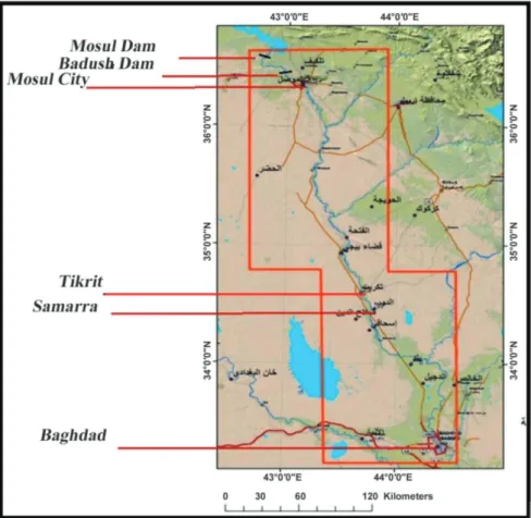
fail-DOI: 10.4236/eng.2019.114014 191 Engineering ure. This study was completed in 1985 by the same Consultants who had de-signed the dam, [5] [6] [7]. The inundation that can result from such an event is so large that losses in human lives, material and infrastructures are beyond comprehension. The map in Figure 1, indicate this area, [8].
The concept of building a “Protection Dam” did not find complete acceptance and there were engineers and experts who argued to spend more money to for-tify Mosul Dam instead of wasting it on such a dam. Many possible solutions were proposed to enhance the dam’s safety such as constructing a diaphragm, but such suggestions were rejected by the International Board of Experts as be-ing unpractical or uneconomical. The Ministry, however, went ahead with its plans and the urgency of the case led to considerable speed in preparing the de-signs and start construction of the dam on the 1st of January 1988. The con-struction went ahead smoothly but it came to a halt at the end of 1990 due to the invasion of Kuwait by Iraq and the following UN economic sanctions on the country. Very high percentages of the construction items were completed at that time, and many attempts have been made since then to resume construction. These attempts, however, did not materialize in any fruitful action so far. The chronic problems in Mosul Dam continue and the need for a solution is an ur-gent matter.
Figure 1. The Map shows the location of both Mosul and Badush dams and the extent of Mosul Dam flood wave and the impounded cities.
DOI: 10.4236/eng.2019.114014 192 Engineering
3. Badush Dam Technical Features
3.1. Design of the Dam
The general features of Badush Dam site are shown in FFigure 2 which indicates the general arrangement of the dam with respect to the Tigris River course in addition to the unfinished dam works left from the end of 1990.
Badush Dam is designed to have enough height to contain the full volume of Mosul Dam wave of 10 billion cubic meters when routed through its reservoir. At the same time, it can utilize the water level difference between the Mosul re-regulating power station and the Badush site to produce electric power before and after the failure of Mosul Dam, [9] [10]. The final design was that of a high dam with a crest at an elevation of 312 (masl). The capacity of the proposed re-servoir was checked by a mathematical model and verified on a physical model and it proved to be enough for the routing of the anticipated Mosul Dam flood wave. The general layout of the dam is given in Figure 3. The locations and layouts of the two saddle dams required to seal the periphery of the future re-servoirs are shown in Figure 4. These two saddle dams have heights of 11and 22 meters respectively. The main characteristics and design and operation parame-ter of the dam are as shown in Table 1.
The design of the earthfill dam, which forms the first part of the dam, is illu-strated in Figure 5 which shows a typical cross-section of the dam in the original river channel. This indicates clearly its temporary use from elevation 260 (masl) upward; which is reflected in the thin inclined clay core and other embankment details. The assumption made was that the upper part of the dam above eleva-tion 260 (masl) was meant to funceleva-tion for a few months only, in which time the reservoir would be emptied quickly. The same thing was also very clear in the design of the foundation treatment works. This was based on the assumption
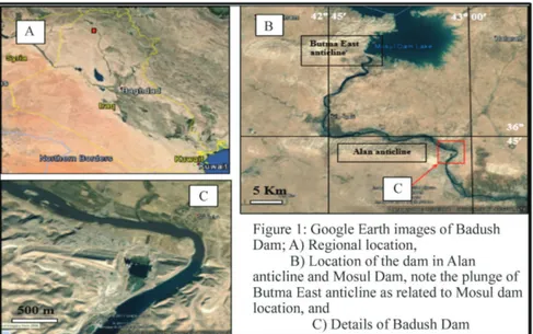
Figure 2. Badush Dam Site location and an aerial view of the unfinished dam’s work from Google Earth.
DOI: 10.4236/eng.2019.114014 193 Engineering Figure 3. Badush main dam General Layout [10].
Figure 4. Badush Saddle Dams on the Left Bank [10].
Figure 5. Details of Badush Dam Earthfill Embankment [10].
Table 1. General data of the proposed dam.
General data of the dam Units Annual average discharge 667 m3/s
Maximum Probable Flood at Mosul Dam 27,000 m3/s
Flood with (0.1%) Probability at Mosul Dam 12,000 Design flood during operation
(Routed through Mosul Dam to be passed through Badush Dam) 8000 m
3/s
DOI: 10.4236/eng.2019.114014 194 Engineering Continued
Design flood level for the normal case 250 masl Normal operation level for the normal case 245.5 masl Minimum reservoir level for the normal case 243.8 masl Spillway capacity 4000 m3
/s No. of bottom outlets 8 Total bottom outlets capacity 8000 m3/s
Dam crest level 312 masl Length of the Dam crest 3730 km Crest level of the Concrete Ungated Spillway 300 masl Maximum height of the Concrete Dam 87 m
Length of the Concrete Dam 248 m Installed Installed capacity of the power station 170 Mw
that the deep rock layers would not be affected by the very limited hydraulic head during the normal operation of the dam, and the high increase in the hy-draulic head in the case of the flood wave impounding will be temporary and will not last very long. So the foundation treatment concentrated much more on the normal operation case.
The second part of the dam was the concrete hollow gravity and buttress dam which was formed of two distinct sections. The first section houses the bottom outlets and the ungated spillway at the top of it, while the second section con-tains the power penstocks leading to the powerhouse building at the toe of the dam.
3.2. General Technical Parameters
The general technical feature and operation parameters are summarized and presented in Table 1.
4. Geology of the Dam Site and Foundation Treatment
4.1. General Geology and Site Investigations
An extensive geological site investigation was carried out on the onset of the planning report preparation which comprised geological mapping and borehole drilling with core recovery. Geophysical investigations were also done using seismic refraction and geo-electrical sounding. Laboratory testing on obtained rock samples was performed in addition to Petrographic and Paleontological studies for obtaining the required rock quality and strength parameters, in addi-tion to chemical tests on groundwater sample, [9] [10]. More geological borings and laboratory testing were done later on in 2009 during an assessment study of the project designs, [11]. These investigations and studies concluded that the rock formations in the project area were entirely of sedimentary origin from Miocene to resent ages. The litho-stratigraphical sequence of the bedrock layers was composed of Lower Fars formation (Fatha Formation) and Jeribe Euphrates Formation. Continuity of the bedrock formations of Jeribe and lower Fars (Fatha
DOI: 10.4236/eng.2019.114014 195 Engineering Formation) in the area was confirmed, as no serious displacements were ob-served except for some small faults of a meter range in the vertical direction. Moreover, the boundary between lower Fars (Fatha Formation) and Jeribe for-mations was slightly undulating. Thus, the beds of the Lower Fars (Fatha Forma-tion) overlaying the contact appeared as marl or marly limestone, chalky limes-tone and conglomeratic deposits. One thick gypsum layer was found at the con-tact between Lower Fars formation and Jeribe formations at the left end of the dam which may have resulted of deposition in an isolated basin’s part. Both formations (Lower Fars and Jeribe) were found to be considerably water perme-able, thus grouting works (grout curtain, blanket and consolidation grouting) are required. The designs considered that the main earthfill dam would be car-ried out on both rock formations. Principally most part of the core trench will be placed on Jeribe rock formations, but short lengths at the left and right ends, however, will be found on the Lower Fars (Fatha Formation). Foundations of the concrete structure (concrete dam, powerhouse) were proposed to be carried out on Jeribe rock formation. The rock had a modulus of deformability ranging from 2800 to 3500 MN/m2, and they were considered as competent foundation rocks, and they could bear safely the concrete structures.
The saddle Earth-fill dams’ foundation (core trenches) were to be excavated partly in stiff clayey materials and partly in marl, so that clay core could be founded on both media, respectively”. An independent study on the general ge-ology of the area had established that the presence of the Lower Fars formation (Fatha Formation) means the existence of active karstification phenomena in the form of solution units, sinkholes of different shapes and sizes. Similarly, the Je-ribe limestone formation suffers from jointing, cracking and well-developed so-lution channels in its limestone beddings. The whole geological setting encou-rages further dissolution channels and formation more sinkholes, [12]. FFigure 6 taken from this study shows that the exposed geological formations and main quaternary sediments close to the site area does not seem to differ much from the Mosul dam site.
In Summary, the accumulated data on the details of the stratigraphy shows that 1) Euphrates Formation (Lower Miocene) is exposed in the core of Alan an-ticline and it consists of well-bedded, hard limestone and marly limestone, but the rocks are highly karstified. The thickness of the formation ranges from (26 - 50) m. The larger length of the dam foundations rests on the rocks of this forma-tion; therefore, the foundations will suffer from karstification, which will in-crease in activity after filling of the reservoir, 2) Fatha Formation (Middle Mi-ocene) forms the bulk of Alan anticline itself (other than the core) and sur-rounding area, and it is divided into Lower and Upper Members. Both members consist of cyclic sediments of green marl, limestone and gypsum, with reddish brown claystone in the Upper Member. The gypsum and limestone beds are highly karstified. The thickness of the Fatha Formation ranges from 117 m at the left bank and 350 m at the right bank, 3) River terraces from (Early Pleistocene) are accumulated in different parts, especially north of the dam site. The pebbles
DOI: 10.4236/eng.2019.114014 196 Engineering Figure 6. Geological map of Badush Dam site and near surroundings. Mosul Dam is shown at top left (After [12]).
of the terraces consist of limestone, silicate and igneous and metamorphic rocks cemented by gypsiferous and sandy cement while residual soil (Holocene) covers large parts of the surroundings of Badush Dam. It is reddish brown, clayey and gypsiferous soil, and finally, 4) the flood plain sediments (Holocene) are developed along the Tigris River. The sediments consist of sand, silt and clay (Figure 7).
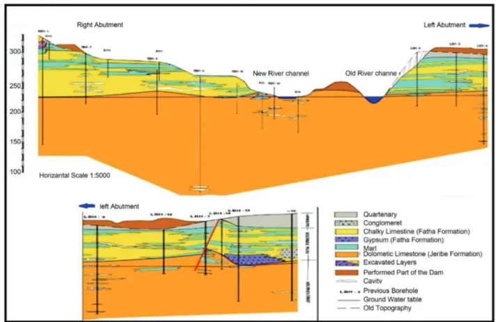
The geological long section along the axis of the dam is shown in Figure 8. The continuation on the left end is shown in the bottom part of this figure.
One recent paper on the geology of the area, that was prepared in collabora-tion with the authors, and published in 2018 expressed serious concerns over the suitability of the site for building a high dam on this site, having in mind the un-pleasant experience in Mosul Dam, and karstified gypsum and highly developed sinkholes are very common in Badush Dam area. One of many other examples in the surrounding area is shown in Figure 9, [13].
It may be said that Badush Dam site is very similar to that of Mosul Dam, and therefore, it requires an extremely cautious approach to the foundation treat-ment and to the sealing of the periphery of the reservoir against seepage and this warranties revision of the criteria design of the already completed grouting works.
4.2. Foundations Treatment Works
The design criteria of foundation treatment were as follows:
1) To adopt a design head of 20 m which represents the head difference when the dam is in permanent operation as a run off the river power generation facility,
DOI: 10.4236/eng.2019.114014 197 Engineering Figure 7. Enlarged Surface geology map of Badush Dam site showing its axis which coin-cides with Alan anticline axis [11].
i.e.) maximum operation water level of 250 (masl), and downstream water level about 230 (masl).
2) Foundation treatment shall be done by using blanket grouting in the dam base, and a central single row grout curtain of 50 meters depth under the full length of the dam.
3) The high hydraulic head difference of (57) m would be realized during the impounding of Mosul Dam flood wave which attains a water level elevation of 307 (masl). According to these criteria, it will be a transient case that takes place for a very short period until the reservoir is emptied. No additional treatment than the above-prescribed treatment is required except the provision of two drainage curtains to safeguard the concrete dam against uplift force, at the same time no appreciable change would occur to the deep rock formations under the dam during this short period.
According to these criteria, the following details were adopted:
1) For the earth fill embankment, a cut-off trench under the clay core is to be excavated down to the required depth to be filled with clay after performing dental concrete treatment to the foundation surface and constructing the grout curtain. On the right side, the trench is to be placed on the limestone formation for a length of 1280 meters measured from the river bank to the right side end,
DOI: 10.4236/eng.2019.114014 198 Engineering Figure 8. Long Section along dam axis; left part is shown in the bottom of figure [11].
Figure 9. Karstified gypsum beds in an industrial site south of Badush Dam site, about 15 Km. (TOP: The photograph shows large subsurface karst (limited by the red line) which papered after excavation of the rocks of Fatha formation. Note circular form at the upper left corner which indicates a subsurface karst.) (BOTTOM: Note the absence of the gypsum bed (white co-lored) in the facing cliff; surrounded by the red line. The three arrows point to the three sinkholes in the floor of the site [13]).
after which it would be continued through the Fatha Formation for another 200 meters to the point where the grout curtain is terminated. On the left bank, the trench is to be excavated down to the limestone rock for part of its length and the remaining part through the Fatha Formation and would finish at the end of the grout curtain approximately 250 meters from the left river bank, Figure 10.
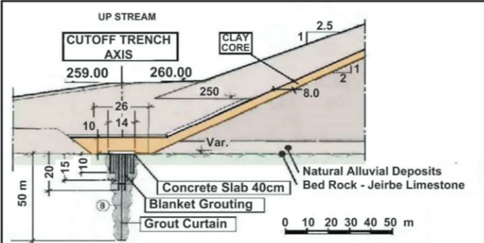
DOI: 10.4236/eng.2019.114014 199 Engineering Figure 10. Details of grouting works under the embankment.
Figure 11. Details of grouting works under the concrete structure.
concrete slab 0.4 m thick at the bottom. The blanket itself would be formed from 8 rows, 1.5 m × 1.5 m grid of grouting holes. The holes are in a staggered form and have depths of 10 meters at the edge of the blanket which increases to 20 meters at the centerline. This would bring the width of the grouted zone to 12 meters. The central row holes in the blanket are extended down another 30 me-ters to form the deep grout curtain which then will have a total depth of the 50 meters under the base of the cut-off trench.
3) With respect to the concrete dam, the foundation excavation is to be done by excavating to reach the Jeribe formation first, then by removing 10 meters of the top limestone of this formation which is badly fissured and jointed. Then this 10 m depth is to be filled with mass concrete in order to form the surface on which the foundation slab is to be concreted. Grouting works of the consolida-tion blanket grouting should follow. The construcconsolida-tion of the deep grout curtain, however, can be done later on from a grouting gallery in the dam itself as shown in Figure 11. The consolidation grouting is to be applied to the whole area of the foundation slab with the grout holes drilled in a grid of 3 × 3 meters and depths of 10 meters and 5 meters as shown in Figure 11. The 50 meters deep grout cur-tain is to be constructed from a grouting gallery and it will have a similar speci-fication to that under the embankment.
DOI: 10.4236/eng.2019.114014 200 Engineering 4) Two drainage curtains are envisaged to relief uplift pressure build-up under the concrete structure foundation joints. These curtains would be at distances of 6.67 meters and 60.9 m downstream from the grout curtain and having 30 me-ters and 5 m depth below foundation level respectively. All holes were to be at 3 meters spacing and to have a diameter of 146 mm. Perforated plastic pipes which were to be wrapped by two layers of plastic mesh filter would be inserted in these holes and would have taps at their tops so to discharge the drainage flow into two drainage galleries as shown in Figure 11. This drainage water would then be collected in a common sump to be pumped out by the central pumping station in the powerhouse.
5. The Uncertain Future of Badush Dam
The uncertainties on the future of Badush dam stem from two factors; 1) the uncertain future of Mosul Dam itself, and, 2) if a decision is taken on the meas-ures to be adopted for Mosul Dam, then the question will arise on the function to be assigned to Badush Dam itself, and what will be the changes required in this dam.
Clearly, this dam was envisaged originally as a semi-dry retention dam to contain Mosul Dam flood wave if Mosul Dam would collapse, and it was de-signed accordingly. The conflicting opinions over the Mosul Dam future neces-sarily have reflected on the Badush dam as follows;
1) The first comprehensive assessment of Mosul Dam safety carried out in 2004-2005 did not favour using a diaphragm as the anti-seepage work and re-tained Badush Dam as already designed as a onetime protection structure, [14].
2) The next assessment in 2006-2007 by a Panel of Experts called for installing diaphragm in Mosul dam driven from its crest down to considerable depth, so this study called for forgetting about Badush Dam as a protection dam, moreo-ver, it recommended to remodel it to a run of river generating facility as a low dam only, [15].
3) Following this in 2009, a study by a joint venture of consulting firms rec-ommended that if a diaphragm is installed in Mosul Dam then only minor de-sign modifications to Badush Dam are to be made, although grouting works in the dam foundations were still needed to be revised and that the bulk of the concrete volume already placed at the abutments of the concrete dam must be removed and the construction of the dam needs not to go higher than elevation 260 (masl). If however, a diaphragm is not installed in Mosul Dam then the same study suggested major design changes including the installation of a di-aphragm in Badush dam itself as this dam is still needed as a protection dam with power generation as a run of river facility, [11].
4) In 2014 in a new study by yet another consulting joint venture recom-mended the need for completing Badush Dam, and considered that its value as flood protection work was so high, in view of the human life and material losses, that it surpassed any economic consideration. Besides, any cost-benefit analysis
DOI: 10.4236/eng.2019.114014 201 Engineering based on power generation would be meaningless. Therefore, this study urged strongly for the completion of this Dam, [16].
5) In May of 2016, an international workshop on Mosul Dam safety was orga-nized by Luleå university and convened in Stockholm with the participation of world known dam and foundation experts; one of the suggested solutions was to convert Badush Dam to a multipurpose dam as a replacement for Mosul Dam, [17].
The argument behind this was as follows:
1) It was not possible to keep Mosul Dam in service for an indefinite future time by continuing the maintenance grouting works, and grouting cannot be considered as a permanent solution.
2) It was recognized that these grouting works were, in essence, replacing the competent foundation rock with good (RQD) by less competent grout material which is in itself friable and not stable. This fact had been long recognized by a study that was carried out in 2006 and compared rock cores of recently drilled boreholes with previous ones in the same locations in the foundation, [18], and therefore the decision to decommission the dam must be taken sooner or later
3) If Badush dam is going to be constructed as a retention dam only the di-aphragm will be needed in any case in view of its doubtful geology as it became clear from the previous studies.
4) Since the construction of a diaphragm represents a major cost item it is re-levant to redesign and construct Badush Dam as a multipurpose dam to replace Mosul Dam and take its full role, and then the Mosul Dam reservoir can be emptied in a controlled manner into the Badush Dam reservoir; this should be done while there is enough time. Staged construction of Badush Dam may be proposed and Mosul Dam may be decommissioned in the last stage as in (Figures 12-14).
In order to check the required design changes, if Mosul Dam was to be re-placed by Badush Dam, a preliminary study was carried out by the authors to find the implications that may arise from this and the extent of the necessary changes to the finished work items. This study involved reviewing first the orig-inal designs thoroughly and followed all the subsequent studies aforementioned.
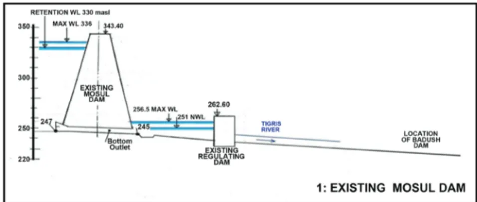
Figure 12. Existing Mosul Dam without Badush Dam, showing the Mosul Re-regulating dam.
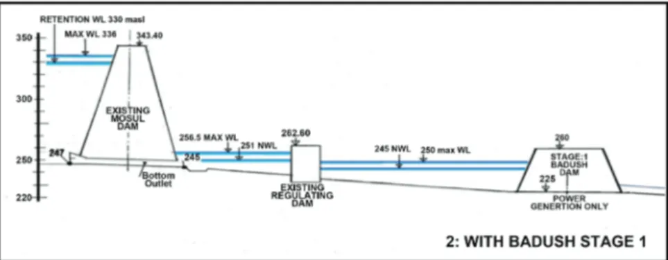
DOI: 10.4236/eng.2019.114014 202 Engineering Figure 13. Mosul Dam with Badush Dam (stage 1), showing the Mosul Re-regulating dam.
Figure 14. Full Badush Dam after Mosul Dam failure or decommissioning.
Taking into consideration the current state of Mosul dam, this preliminary study defined a new set of requirements if this new objective is adopted.
6. Requirements for a New Design
The completion of Badush Dam must take into consideration the fact that its site geology is not better than the Mosul Dam site, if not the same. Although placing most of the length of the dam on the Jeribe limestone formation making up the core of Allan mountain, this does not exclude the negative presence of the Lower Fars (Fatha Formation) with its soluble beddings around and adjacent to the dam body and forming also the most of the reservoir periphery. Moreover, the limestone of the Jeribe formation with its caverns and Karstification and the re-sulting high permeability does not offer a satisfactory answer to the required quality of the foundation of such an important structure.
Adding to all this, the quantity of the executed geological borings done so far is judged as not enough to give accurately the stratigraphy at the site, and there is a lack of the number of the drilled deep boreholes as seen from Figure 8. Many more 250 - 300 m deep boreholes must be performed and shall be sub-jected fully to in situ Lugeon permeability tests so that the complete permeability profile in the foundation is obtained.
An outline design is offered in the preliminary study. Taking as a precedent the case of grouting in Mosul Dam foundation, such grouting will be ineffective
DOI: 10.4236/eng.2019.114014 203 Engineering in Badush Dam foundation also. A positive cut-off in the form of the concrete diaphragm is suggested. The maximum recommended depth of such diaphragm is 1.5 times the acting hydraulic head on the foundation or beyond the last major karstified and cavernous bed that exists in the foundation, whichever is larger.
A new set of hydraulic calculations is proposed starting with routing the PMF that originally was routed through Mosul Dam, i.e. 27,000 cubic meters per seconds. The study concluded that after fixing the new maximum operation wa-ter level as a result of this routing, the service spillway and the bottom outlet’s designs shall be changed drastically. A new gated spillway shall be installed in the body of the concrete dam; its sill is to be fixed in lieu with the new maximum operation level.
The present ungated spillway at the dam crest is to be eliminated and replaced by an auxiliary spillway which shall be placed in the left bank, and it shall be in the form of a morning glory intake combined with a vertical shaft and tunnel which discharges into the downstream of the dam. Four of the bottom outlets can be eliminated completely, and two more of the remaining shall be converted to irrigation outlets. The other remaining two bottom outlets may be retained for emptying the reservoir in cases of emergency after resizing them. This process may result in revising the height of the dam which must have ample freeboard above the maximum operation water level.
The next step that followed from the study was to look into the design of the earth embankment. Clearly, the present design does not offer a good design for permanent storage. The dimensions of the thin clay core need to be increased to allow lowering the phreatic surface within it considerably, which with the help of ample filter layers on both sides ensure safe exit gradients and prevent any suf-fusion of the clay core materials. If such enlargement is not possible due to the existing partially completed earthworks, then it may be possible to have a small-er clay core but this must be compensated by a central concrete diaphragm which can be constructed meter after meter as the filling of the dam continuous up. Utmost care must be exercised to join this diaphragm with the other diaph-ragm in the foundations.
Much more details have to be looked into, not less of them the provision of suitable upstream slope protection, the instrumentation systems design, the Po-werStation design and its new installed capacity and the newly required equip-ment, the design of the hydromechanical control equipment and more. These details are beyond the preliminary study which looked only into the broad out-lines design changes.
Outside the dam itself, other important issues must be resolved. These involve defining the modification required to ensure the supply of the irrigation water to the existing North Jazira project from Badush Reservoir instead of the present supply from Mosul Dam. Similarly this must be done for the water supply to the planned East Jazira and South Jazira projects. These works may require a lot of planning and surveying works to determine the alignments of the new feeder’s
DOI: 10.4236/eng.2019.114014 204 Engineering canals and redesign of their intakes.
7. Conclusion
The major conclusion of the study was the recognition of the fact that Mosul Dam in its present state represents a grave hazard on the Tigris River Valley, and the ongoing maintenance grouting does not offer a permanent solution in the future. As the diaphragm construction represents an unfeasible solution, neither technically nor economically, does Badush Dam remain as the only safeguard against Mosul Dam flood wave in case of its failure. The transformation of Ba-dush Dam from a protection dam to a multipurpose dam in order to replace Mosul Dam is not an easy task. This may require considerable additional geo-logical investigation and a lot more of studies and new designs as outlined al-ready.
Conflicts of Interest
The authors declare no conflicts of interest regarding the publication of this pa-per.
References
[1] Lunsford, D. (2018) Retention Dams Sonora Prevented Additional Damage during Disastrous Flooding. Natural Resources Conservation Service.
https://eu.gosanangelo.com/story/news/local/2018/10/10/sonora-dams-prevented-more-damage-during-disastrous-flooding/1581052002
[2] Sumi, T. (2015) Designing and Operating of Flood Retention “Dry” Dams in Japan and USA. http://ecohyd.dpri.kyoto-u.ac.jp/content/files/sumi-paper/2008/ICHE.pdf [3] Johannesson, T. and Barbolini, M. (2014) The Design of Avalanche Protection
Dams; Recent Practical and Theoretical Developments.
https://www.researchgate.net/publication/260908048_The_design_of_avalanche_pr otection_dams_Recent_practical_and_theoretical_developments
[4] Londe, P. (1987) Personal Correspondence with the Writer.
[5] Swiss Consultant Consortium (1984) Task2, Mosul Dam Flood Wave, Summary. Vol. I.
[6] Swiss Consultant Consortium (1984) Task2, Mosul Dam Flood Wave, Model Cali-bration. Vol. II.
[7] Swiss Consultant Consortium (1984) Task2, Mosul Dam Flood Wave, Mosul Flood Wave Calculation. Vol. III.
[8] Adamo, N. and Al-Ansari, N. (2016) Mosul Dam Full Story: What If the Dam Fails?
Journal of Earth Science and Geotechnical Engineering, 66, 245-269.
https://www.academia.edu/29478019/Mosul_Dam_Full_Story_What_If_The_Dam_ Fails
[9] Energoprojekt (1988) Basic Design Report for Badush Dam Project. Beograd. [10] Energoprojekt (1989) Final Design Report for Badush Dam Project. Beograd. [11] El Concord, L.L., Rizzo, P.C., Energoprojekt, Medingeneria. (2009) Badush Dam
Project Design Adjustments and Design. Vol. 2a Final Design. The Dam.
DOI: 10.4236/eng.2019.114014 205 Engineering Quadrangle, Scale 1:25000. 2nd Edition, Iraq Geological Survey Publications, Bagh-dad.
[13] Sissakian, K., Adamo, N., Al Ansari, N., Knutsson, S. and Laue, J. (2018) Badush Dam, NW Iraq; A Geological Study. Journal of Earth Science and Geotechnical En-gineering, 88, 1-15.
http://ltu.diva-portal.org/smash/get/diva2:1186811/FULLTEXT01.pdf
[14] Washington Group International and Black & Veatch JV (2005) Mosul Dam Study Final Report. Task Order No. 8.
[15] MWH Global (2007) Mosul Dam, Issues and Challenges.
[16] EDR GmbH, Cedre Team International (2014) Badush Dam. Final Feasibility Study Report.
[17] The Lålue University of Technology (2016) The Final Statement on Mosul Dam.
International Workshop on Mosul Dam, Stockholm, 24-25 May 2016.
[18] Kelly, J.R., Wakeley, L.D., Broadfoot, S.W., Pearson, M.L., McGrath, C.J., McGill, T.E., Jorgeson, J.D. and Talbot, C.A. (2007) Geologic Setting of Mosul Dam and Its Engineering Implications. USACE-Engineer and Development Center.
![Figure 4. Badush Saddle Dams on the Left Bank [10].](https://thumb-eu.123doks.com/thumbv2/5dokorg/4426717.106497/5.892.319.798.131.364/figure-badush-saddle-dams-on-the-left-bank.webp)