http://www.diva-portal.org
Postprint
This is the accepted version of a paper published in Computer-Aided Design and
Applications. This paper has been peer-reviewed but does not include the final publisher proof-corrections or journal pagination.
Citation for the original published paper (version of record): Heikkinen, T., Johansson, J., Elgh, F. (2018)
Review of CAD-model Capabilities and Restrictions for Multidisciplinary use Computer-Aided Design and Applications, 15(4): 509-519
https://doi.org/10.1080/16864360.2017.1419639
Access to the published version may require subscription. N.B. When citing this work, cite the original published paper.
Permanent link to this version:
Review of CAD-model Capabilities and Restrictions for Multidisciplinary use
Tim Heikkinen[0000-0002-9337-791X], Joel Johansson[0000-0003-1162-724X] and Fredrik Elgh[0000-0002-3677-8311]
Corresponding author: Tim Heikkinen, tim.heikkinen@ju.se
ABSTRACT
Product development is an iterative process, partially due to changes in both company internal and external product requirements, resulting in changes to the product under development. These changes might require recapitulation of design rationale and result in re-doing assessments and syntheses of different kinds. One way to support this work is to proactively model in such a way that as much as possible of the previous work can be re-used. Not only within one product development project but also across and to future ones. Modelling for re-use can be done by documenting design rationale and formalising performed activities as design guidelines or
computer scripts. To be able to find and re-use this information it could be attached to the product features which it relates to. Since geometry is such a core product characteristic, especially within the mechanical industry, and is often modelled as CAD-models, this paper presents a review of CAD-model capabilities and restrictions to serve as a carrier of multidisciplinary information. This is done by; enquiring three Swedish companies, exploring an automated Finite Element Analysis method utilising the CAD-model as a carrier of information, and reviewing different CAD software capabilities. Results show that there are at least seven extension techniques, out of which all are currently being used or considered to be in the future, by at least one company. Further, depending on the extension technique, extendibility and human-comprehension of the added information differ.
Keywords: computer-aided design, computer supported engineering, simulation-ready cad-models, knowledge re-use
1 INTRODUCTION
Product development (PD) can be defined as a business process, turning a market opportunity to a product available for sale [13]. Throughout this process, product data is being created, modified and re-used. Example of such data includes requirements, functional attributes, conceptual descriptions, geometric parameters, constraints and other product related data. The formal representation of this data is called a product model [9]. The product model is a complete and unambiguous representation of the product [20] and is a part of the entire product life-cycle. After PD, it is in the hands of the marketing and sales as well as production department who use it as a foundation to sell and produce. The product model is multidisciplinary and the result of several professions collaborative work. Some examples within the engineering design perspective are simulation, manufacturing, and geometric-modelling. Collaboration between these disciplines is crucial as they work with the same product model but with different agendas, often resulting in conflicting aspirations. Iterations within the PD process are commonplace and can occur when changes are made to product features which are shared among disciplines or when requirements change.
Iterations might require recapitulation of design rationale and result in re-doing design activities of different kinds, such as assessments and syntheses. Efficiently and effectively being able to re-use design activities is therefore important within PD projects, but also between projects where similar activities are performed. To support re-usability of any repeating activities the rationale behind them could be documented and guidelines to repeat them could be made. This paper
focuses on a third option where the activities are formalized as computer scripts, to enable automation. Automation can in this way be used to improve the ability to iterate, which also enables the exploration of more product variants. Exploration of more product variants could in turn be used to design for robustness with respect to shared product features and fluctuating requirements in the first place, also decreasing the negative effects of iterating, or removing the need all together.
Digitalization is a trend manifesting itself in the development of product models. For instance, to increase the competitive potential within manufacturing companies, several different types of computer-simulations have been introduced to improve the effectiveness and efficiency of the PD process. As indicated in [18], where 77 people answered a survey, about 35% of them used computer-based design analysis and 28% expected to do so in the future. Simulations can, compared to physical tests, save a significant amount of time and money to the expense of losing some of the tests reliability. Continuous improvements within the accuracy and efficiency of the simulations have expanded its use within PD. Initially they were mainly concerned with
assurance of the products performance, reliability, and manufacturing costs but are today, in some cases, also used to guide the development process [12].
Product geometry is required of many disciplines for assessment and generation of new
information, e.g. when performing Finite Element Analyses within the simulation discipline, or producibility assessments within the manufacturing discipline, or product-family descriptions within the geometry-modelling discipline. The centralisation of CAD-models as an initial digitalised representation of the product geometry [15], [19] has for this reason made it a potential communication hub for many activities in multiple disciplines. In multi-disciplinary (design) automation, the geometry flows through activities that extract some information to perform specific activities and sometimes add information required for subsequent activities. In many cases, there is a mutual dependency between the information available and the design of the disciplinary methods. Additional information can be required in the geometry model to enable operation of disciplinary methods, improve accuracy, and/or speed.
Communication between CAD- and other models can be achieved in two ways, either a direct translation or an indirect translation utilising a standardised neutral model [16]. Standardised models would reduce the number of translators required and could also provide a more robust approach, since they might not change as much. Limitations in mainly the implementation of standardised models is however the reason why both are still often necessary. Implemented standardised models, such as STEP AP 203, represent design output very well, but still lack in representation of the design activities which describe how they were modelled and to some extent why the product is to be constituted in the way it is defined by the model. Theories have been proposed to solve this limitation, such as the Core Product Model [7], and have also been tested to some extent. This paper focuses on the generalisation of a hybrid approach, where the CAD software and models are used to attach and store information to enable re-usability of activities related to CAD-models, using both direct and indirect translation.
To be able to find and effectively re-use design activities, the added support such as design rationale, design guidelines, or computer scripts, could be attached to or otherwise linked to the product features they relate to. Since CAD-models are such a central part of the PD process, relating to many design activities within multiple disciplines, the questions we asked ourselves were: 1) How can CAD-models be used as carriers of multidisciplinary information? 2) Which of these approaches are most common in industries today? 3) And what differences can be found between them? The rest of this paper starts by introducing the research method. The results are then structured in three parts, starting with a generalized CAD-model description, exploration of an existing method using the CAD-model as a carrier of information, and finally the results from
interviews within three Swedish companies. The paper then concludes with discussions and conclusions drawn.
2 RESEARCH METHOD
This work is part of a research project, called ChaSE (Challenge Fluctuating and Conflicting Requirements by Set‐Based Engineering), where the main objective is to provide “A novel method to develop and describe adaptive technology solutions with an ability to manage changing and conflicting requirements in the development of customised products.” Within this project the Design Research Methodology as described by [2], see Fig. 1, has been employed. The general approach is to define scientifically and industrially relevant goals through literature and empirical data analysis followed by descriptive and prescriptive loops where support methods are developed and evaluated. The work presented in this article is a part of a second prescriptive loop where a method for simulation-ready CAD-models is generalised.
Fig. 1: Design Research Methodology framework [2]
In the previous phases, we found an industrial and scientific need for improved flexibility within product and technology development [1]. A method, called simulation-ready CAD-models, was developed as a means to enable flexibility with respect to Finite Element Analyses (FEA) [10], [11]. As a result of the successful evaluation [8], the method is now attempted to be generalised. The research questions we therefore investigated were; How can CAD-models be used as carriers of multidisciplinary information? Which of these approaches are most common in industries today? And what differences can be found between them? To answer these questions the work was divided in two main tasks:
• Exploration of the existing method utilizing the CAD-model as a carrier of multidisciplinary information. The method has been tested in a feature-based CAD software (Solidworks 2016) and partially presented in [10]. The exploration was conducted by first reviewing the systems
underlying software architecture. Then a partial implementation was made into a direct modelling CAD software, namely SpaceClaim 2016.1. Finally, Catia V5 and Siemens NX 9 were also examined by going through API documentations. Possible ways of storing information within the different systems and its implications on the development of the method were noted.
• Interviewing employees at three large Swedish industrial companies. In lieu of questionnaires directed toward more companies, resulting in more generalizable results, interviews were selected to focus more on getting in depth information. Employees from different disciplines and positions, which were in some way connected to CAD-models, were selected to get several perspectives on the matter. Some key questions were followed during the interview but some flexibility was allowed to investigate interesting topics. The questions explored usage, available methods, added functionality, challenges, and future trends of the CAD-model as a carrier for anything other than portraying the final product geometric shape. This resulted in about 4,5hours of recorded interview material and the interesting results for this paper of which are focused around the usage and challenges expressed.
The three companies investigated work within Engineer-to-order (ETO) business contexts. Company A is a subcontractor in the automotive industry which employs around 300 people in the investigated organization and around 3000 worldwide. Company B develops and
manufactures cutting tools for machining such as turning, milling and drilling. The investigated organization employs 8000 people and belongs to a group, employing around 50000 people worldwide. Company C is a subcontractor to engine manufacturers in the aerospace industry. The company employs around 2000 people in the investigated organization and around 50000 in the group worldwide.
The results from the two main tasks are presented in sections 4, 5, and 6. First, section 3 describes a generalised CAD-model description since it is the object being discussed. A short description of how it has been used as a carrier of additional information in the past is also included.
3 CAD-MODEL CONSTITUENTS
Here we describe what a CAD-model consists of on a general level, and shortly how it differs between two modelling approaches which have an impact on the extension techniques which can be used, see section 4. CAD-models are the objects being examined and therefore deserve some description. CAD-models can be modelled in different ways, for instance feature-based
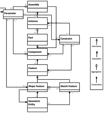
modelling and direct modelling. Depending on which modelling approach one utilises the CAD-model constituents will differ. In this section, we present a generic feature-based CAD-CAD-model which can be seen in Fig. 2 and will be further described below. The difference between a direct modelling model is that the modelling operations are not saved, i.e. no (CAD) features are created. So, in the direct modelling CAD-model the Components are only a collection of Geometric Entities.
Fig. 2 shows how a CAD-model is comprised of an Assembly or Component, both inheriting the Part class. An Assembly can then have Instance-objects which in turn can have other Assemblies or Components. The Instance object is used to define the context specific information such as location in the local coordinate-system, color, etc. Each Component is a collection of Features which can be categorized in several different ways, see for instance [6], [14]. In this context, the categorization is made by Shape and Sketch. Shape Features are defined as functional features directly coupled to geometric shape. Inputs to these functional features can be either references to Geometric Entities, Parameters, or logical expression (e.g. “Up to next surface”). A Sketch Feature on the other hand is a structural feature comprised of a collection of 2D Geometric Entities and can be utilized by Shape Features. A Geometric Entity is either a point, curve, surface, or body, including supporting reference geometry such as reference-planes and axes. Parameters are variable-value pairs, e.g. a variable named “Length” paired with value “5mm”. A Constraint can contain Parameters or logical expressions and can be used by Instance-,
Fig. 2: Generic feature-based CAD-model constituents.
3.1 CAD-model as a representation of more than geometry
There are several ways in which the information can be associated with the product features it relates to. For CAD-models, PDM/PLM systems can do this very well on a file-level by adding meta-data. Neutral CAD-file formats are another approach, such as STEP, which can do this very well on more detailed levels. This paper focuses on the native CAD-models which also has been utilized by others as carriers of information for different purposes. For instance, [17] describes the use of annotations on CAD-models, drawing similarities to the text-based document Markup approach where the purpose was "… to allow computers to manipulate and deal with the contents of the Web on a more sophisticated (abstract) level". An example of the approach was shown where both FEM and CAM specifics were added with annotations to the geometry enabling automatic FEA and blank casting geometry creation. The approach was later incorporated into a framework for Extended Product Models (EPM) where both constraint based redesign activities [4] and encapsulation of in-development/in-service information for throughout product lifecycle retrieval [3] was supported. The information was finally stored outside the CAD-models together with lightweight representations of the geometry, making it easier for more disciplines to work with [5].
4 METHOD UTILIZING THE CAD-MODEL AS A CARRIER OF MULTIDISCIPLINARY INFORMATION
As a starting point for this study an existing method utilizing the CAD-model as a carrier of multidisciplinary information was explored. This method is an updated version of the work presented in [10]. The method enables formalisation of Finite Element Analysis (FEA) from within CAD software and had been realized in a feature-based CAD modeller (Solidworks). ANSA was used as a pre-processor and LS-dyna as a post-processor. The approach was to enable the formalisation and execution of pre-processor operations from within the CAD environment,
Assembly Assembly Parameter Parameter 1 0..* 1 0..* Component Component Shape Feature Shape Feature Instance Instance 1 1 1 1 1 0..* 1 0..* 1 0..* 1 0..* Part Part 1 0..* 1 0..* 1 0..* 1 0..* 0..* 0..* 0..* 0..* Sketch Feature Sketch Feature Feature Feature 0..1 0..* 0..1 0..* Geometric Entity Geometric Entity Constraint Constraint 0..* 0..* 0..* 0..* 0..* 0..* 0..* 0..* 0..* 0..* 0..* 0..* 0..* 0..* 0..* 0..* 1 0..* 1 0..* Association Aggregation Composition Inheritance Association Aggregation Composition Inheritance
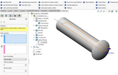
providing a link between geometry and FEA features. Examples of FEA features are mesh geometry such as beam, tetrahedron, pyramid, and triangle elements as well as FEA properties such as material, constraints, and boundary conditions. To do this the traditional CAD-model geometry was not always enough and was therefore extended with additional geometric entities, created only for FEA. As an example, see surface within bolt in Fig. 3 which is used to create a structured triangular mesh utilising the rotation operation. Programmed features (known as macro-features in Solidworks) had been made which when instantiated provided an easy to use user-interface with the necessary inputs, such as geometry, strings, and numerals, illustrated on left-hand side in Fig. 3. Just as any other CAD-feature it was placed in the feature-tree which can be seen in the centre of Fig. 3 called MeshPart1. In this way, it was a part of the CAD-rebuild process and updated according to any related changes made. The execution of the programmed-features was separated to run all in one go in contrast to the other functional programmed-features. To automate pre-processor operations within ANSA a template macro-script had been made where each FEA operation had a specified code-section with the inputs required noted with special characters (@ signs), see Fig. 5. In this way, each programmed-feature could copy the necessary code-sections and replace the needed inputs at the given position. Geometric inputs were
exported in a neutral CAD-file format (Parasolid) and the components names were used as identifiers.
Fig. 3: Existing method realisation in Solidworks 2016. On top, we see buttons for instantiation of programmed features. Then, on the left side there is a graphical user-interface for the programmed feature “Add Mesh Part”, followed by its representation within the model-tree, namely “MeshPart1”, and finally an added surface constrained to a solid bolt geometry. The added surface is necessary for the FEA operation revolve used to idealise the bolt as a structured
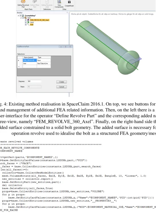
Fig. 4: Existing method realisation in SpaceClaim 2016.1. On top, we see buttons for the adding and management of additional FEA related information. Then, on the left there is a graphical user-interface for the operator “Define Revolve Part” and the corresponding added name in the
tree-view, namely “FEM_REVOLVE_360_Axel”. Finally, on the right-hand side there is an added surface constrained to a solid bolt geometry. The added surface is necessary for the FEA
operation revolve used to idealise the bolt as a structured FEA geometry/mesh.
Fig. 5: Part of Ansa-template script showing code-section for FEA operation revolve. To further understand CAD-model capabilities and restrictions the method was applied to a direct modelling software (SpaceClaim), see Fig. 4. Direct modelling software does not save the
operations history and therefore needed another approach to the parametric feature based implementation. Instead of programmed features, a naming convention was used (the same as introduced in the older parametric feature version presented in [10]) applied to both geometric entity name attributes and additionally added attributes. Name attributes could be used to store all the information necessary but quickly become incomprehensive for human users as the
information content size grows. Only the links between geometric FEA features (e.g. beam, tetrahedron, triangular etc.) are therefore using this approach, see example name in tree-structure left-side of Fig. 4. FEM properties (e.g. material, constraints, boundary conditions etc.) instead use additional attributes. Remembering a naming convention is however not reasonable and support tools were therefore created working as CAD operators for renaming and adding
attributes to the CAD components, see example user-interface in lower-left side of Fig. 4. Also, interfaces for proper overviews of the FEA links present in the models were created, working essentially as custom-made functional feature-tree viewers.
5 EXTENDED CAD-MODEL TECHNIQUES
Within the exploration described above in section 4, and out of further investigation of software API documentation within Siemens NX 9 and Catia V5, we found seven extension techniques summarised in Tab. 1. Almost all four CAD software reviewed had all the extension techniques available, with exception to bundled as well as programmed features in SpaceClaim. The noteworthy differences were with respect to the range that information could be manually inserted to the model objects and to which degree executable-information, such as code and mathematical equations, could be modelled and embedded into the model.
The extension of CAD-models can be either contained inside the CAD-model which requires the CAD software to have such functionalities or it can be stored outside of the CAD-model which requires standalone software or add-ins to establish a link. Most often they are hybrids. In both implementations described in section 4 the information was stored both inside and outside but to a varying degree. Within the feature-based CAD software implementation the programmed-features could be fully embedded, ensuring that the FEA feature input was up-to-date at all times in an event of execution. The information related to the actual execution was stored outside however as an add-in, providing a connection between a pre-processor session, pre-process template-scripts, some pre-defined meshing properties such as quality and size, as well as load cases. For the direct modeling implementation only the names and additional attributes, attached to the geometric entities, were stored inside the CAD-model. There was no process-context, as the rebuild process in the feature-based CAD software, to attach code.
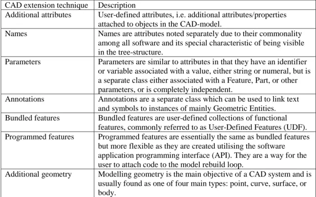
CAD extension technique Description
Additional attributes User-defined attributes, i.e. additional attributes/properties attached to objects in the CAD-model.
Names Names are attributes noted separately due to their commonality among all software and its special characteristic of being visible in the tree-structure.
Parameters Parameters are similar to attributes in that they have an identifier or variable associated with a value, either string or numeral, but is a separate class either associated with a Feature, Part, or other parameters, or is completely independent.
Annotations Annotations are a separate class which can be used to link text and symbols to instances of mainly Geometric Entities. Bundled features Bundled features are user-defined collections of functional
features, commonly referred to as User-Defined Features (UDF). Programmed features Programmed features are essentially the same as bundled features
but more flexible as they are created utilising the software application programming interface (API). They are a way for the user to attach code to the model rebuild loop.
Additional geometry Modelling geometry is the main objective of a CAD system and is usually found as one of four main types: point, curve, surface, or body.
6 INTERVIEW STUDY
To get an understanding of how industry use CAD-models as carriers of multidisciplinary information a set of interviews were carried out at three Swedish companies (section 2 provides more information about each company). Each interviewee was asked about their position, which software they used, what CAD-model extension techniques they knew the company used, and what challenges they had experienced with it.
Within Company A one interview was carried out with a consultant who works within both the geometric-modelling and simulation discipline. The interviewee’s main responsibility was to enable automation of different kinds and worked with CAD-, simulation-, and automation-systems. At Company B three interviews were carried out. The interviewees positions were geometry-modeler, methods developer within automated geometry modelling, and methods developer within geometry-modelling. The geometry-modeler utilized mainly CAD but also some simulation software to model the geometry of tool bodies. The methods developer within automated geometry modelling utilized CAD, Product Life-cycle Management (PLM), and automation software. This employee’s main responsibilities were to check the novelty of the technologies proposed within technology development projects as well as further develop the methods utilized. The methods developer within geometry-modelling utilized CAD and PLM to standardize geometry-modelling methods, to ease the introduction of new employees and to ease the re-usability of CAD-models within CAD, CAM, CMM, and design automation software. Finally, at Company C five interviews were conducted. Four of the interviewees were structural analysts working within both technology and product development, focusing on both automation methods for meshing and/or solving. They all worked with automation of engineering processes in some way. One did not use CAD at all, one used process management software (HyperStudy), and all used simulation software. The fifth employee was a geometry-modeler within technology development working with parametric shell and solid models utilizing CAD software, a little simulation, and automation. This employee's responsibility was to maintain and create parametric CAD-models for automated variant creation.
Almost all the techniques presented above for extending the CAD-models were used at each case-company, except Annotations (although this was planned for in the future in Company B). To which extent each company used the different techniques can be seen in Tab. 2 below (see Tab. 1 for more information about the different techniques). Company A used SolidWorks and Companies B and C Siemens NX.
CAD extension technique
Company A Company B Company C
Names No Yes Yes
Additional attributes No Yes Yes
Parameters No Yes Yes
Annotations No No No
Bundled features No Yes No
Programmed features Yes No Yes
Additional geometry Yes Yes Yes
Tab. 2: Utilized CAD-model extension techniques at case-companies.
Several challenges were expressed during the interviews. For instance, all available methods for managing or elaborating the CAD-model extensions were not always complete and sometimes hard to use because of the large amount of information stored within them. They were also all directed towards geometric-modelers who were thought of as the responsible person to add all the information, even though it was utilized by others. Utilizing nomenclatures was one aspect which made this difficult. The first company, however, used programmed features in one application
which utilized graphical user-interfaces instead, eliminating the need for a nomenclature for the users.
In addition to the challenge regarding methods discussed above, a challenge expressed in two of the companies was the displeasure to administer the addition of the information. Geometric-modelers ask themselves "what is in it for me" when required to administer multidisciplinary information, and other disciplines do not want to work in the CAD software or may not have access to a license.
Other challenges were also expressed regarding software updates, modelling robust and flexible CAD-models, knowing what information disciplines need, and managing the trade-offs between mesh quality and size as well as geometric simplicity and realistic product representations. When it comes to the management of the trade-off between geometric simplicity and realistic product representation both companies A and B had methods where both models were represented. The first company utilized the method described previously in section 5 which focuses on the definition of FEA operations from within the CAD software. In this way, the FE-model is implicitly defined and represented. Company B had gone one step further and automated the CAD-model creation process and could therefore utilize this as a recipe, choosing to skip different parts of the modelling to produce simplified CAD-models for different purposes, such as simulation.
7 DISCUSSION
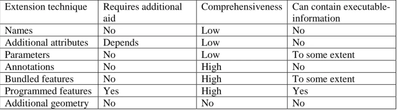
In this section, first a review of the extension techniques presented in Tab. 1 is made with respect to three aspects; required additional aid, comprehensiveness, as well as whether they can contain executable-information. Each aspect is discussed one by one in the sub-sections 7.1-7.3. In summary of the review, see Tab. 3. Finally, section 7.4 discusses CAD-model extension techniques with respect to the future challenges with respect to disciplinary integration.
7.1 Required additional aid
Some of the extension techniques required additional aid in the form of custom applications. These could be either added to the CAD system as add-ins or stay as standalone applications. Creating custom applications for adding the information required in the CAD-models is not particularly difficult but will require maintenance. For instance, in Siemens NX additional attributes could be manually inserted to all geometric entities, from points, curves, surfaces, to bodies, whilst in Solidworks and SpaceClaim they had to be programmatically inserted. Interesting to note also that it is an extensively used technique in both Company B and C who used Siemens NX. Programmed features also need user-interfaces unless the users are supposed to meddle around in the code themselves.
7.2 Comprehensiveness
To be comprehendible the semantics, or meaning/purpose, of the added information needs to be understood by a human-being. This is important since many of the extension techniques produce information which is openly editable by others, such as names for instance. The semantics behind additional geometry is not always understood, it usually requires one or several of the other techniques as well. Take for instance the added surface within the bolt in Fig. 3 and 4, the purpose or meaning of this geometry is not clear unless additional information is attached to it. Attributes and parameters can be comprehensive for humans if the information they convey can be separated into a variable-value relation, e.g. thickness, density, material name etc. Parameters can sometimes be associated with additional notes as well, which increases its
comprehensiveness potential. Names can be used as in the example above, where the name “FEM_Revolve_360_Axel” was used to convey the purpose of the added surface in Fig. 4. For a
human to fully understand the meaning of this information it probably needs to be expanded however, and at some points it becomes too much. Annotations have in contrast to attributes (including names) and parameters the advantage of being visible in the graphical user interface and the possibility to model symbols which greatly add to its comprehensiveness potential. Annotations, feature bundles and programmed features are described as highly comprehendible, as seen in Tab. 3, because they utilize graphical user interfaces. When annotations, feature bundles or programmed features are instantiated or reviewed a graphical user interfaces shows the input such as parameters, pointer to geometric objects etc. in a collective, easy to understand, format.
It should be noted however that the comprehensiveness of information utilizing any of the extension techniques could be made by developing additional aids. These aids could be used to decrypt the information to another user-friendly format, just like the annotations, feature bundles and programmed features.
7.3 Can contain executable-information
Executable-information in this paper is information which expresses logical reasoning and is understood as well as used by a computer-based interpreter, such as programming code or mathematical expressions. It requires an interpreter and can in contrast to other pieces of information express an action, to alter or add more information and notify to different kinds of events.
Parameters can contain executable-information in the form of mathematical equations to describe relations to other parameters. An interpreter in this case understands the formulation of
mathematical equations and can produce new information by retrieving the values from other parameters and performing different kinds of mathematical operations. Feature bundles are pieces of information which can contain a lot of executable information, such as shape features which produce new information in the form of geometry. It can also control its instantiation to express which inputs are required or which have been used to instantiate it. This would also be an
example of executable-information since it requires an interpreter and uses the information within it to produce new information in the form of graphical user interfaces. Programmed features are built upon programming code, either as macro-scripts built with visual basic for applications (VBA) or standalone application built with any language supported by the .NET platform or Java utilizing the CAD software’s API. Any programming code requires an interpreter and with the ones utilized by programmed features the possibilities for creating new information is vast. To embed this executable-information inside the CAD-model you can for instance use macro-features in Solidworks, knowledge fusion (KF) rules in Siemens NX, or Knowledgeware rules in Catia.
Extension technique Requires additional aid
Comprehensiveness Can contain executable-information
Names No Low No
Additional attributes Depends Low No
Parameters No Low To some extent
Annotations No High No
Bundled features No High To some extent
Programmed features Yes High Yes
Additional geometry No No No
Tab. 3: Summary of CAD extension techniques and their individual properties.
7.4 Integration trends and extension techniques
A common concern today is the integration of disciplinary activities and applications to decrease product development lead time and reduce ambiguities in product data. Independent of whether
the process is automated, semi-automated, or manual the management of parallel/integrated processes makes things trickier. Especially considering aspects such as globalization and the use of subcontractors as well as multiple applications. The use of CAD-model extension techniques will also differ with respect to this. Programmed features are very integrated in the specific (CAD) software that is being used, even between versions of the same software, and might not be as practical in these distributed contexts, where PDM-systems most often serves as hubs for information sharing. Instead, using naming conventions upon attributes and parameters might be more suitable. This might cause other maintenance issues however, since they are less
comprehensive (see section 7.2 above), error-prone when added manually, and are not as context-aware (include executable-information). Using support-systems would again introduce the issues of software dependence and maintenance. When it comes to data-related issues the development of standardized product model representations on a more abstract level is an interesting research area. This could open up for more service-oriented and cloud-based approaches for information sharing. If the technical obstacles in this area can be overcome as well as the security issues associated, the extension techniques with respect to the CAD-models might also move more toward programmed features since software dependence would decrease. Programmed features have an advantage in that they can, as mentioned previously, be very integrated in the CAD-model rebuild tree context.
8 CONCLUSION
There is a growing trend in manufacturing companies to utilize CAD-models as potential communication hubs to support re-usability and enable multidisciplinary exploration of their products. We have reviewed several techniques to facilitate such communication in several CAD software to identify pros and cons of these techniques (see section 7.1-3 and Table 3). Our answers to the initial questions which guided this work are based upon both interview studies within three major Swedish companies and close examination of four CAD vendors. The answers can be phrased as follows:
1. How can CAD-models be used as carriers of multidisciplinary information?
We found seven different techniques for adding information to the CAD-models, they were; name, additional attributes, parameters, annotations, bundled features, programmed features, and additional geometry. See Tab. 1 for further explanations. Out of these seven, parameters, bundled features, and programmed features had interpreters allowing them to also model executable-information, see section 7.4 for further discussions.
2. Which of these approaches are most common in industries today?
Within the three companies investigated, two of them used naming conventions applied to both attributes (name and additional ones) as well as parameters. Additional geometry was also used by all of the companies. See Tab. 2 for a full summary.
3. What differences can be found between them?
It can be concluded that there is a trade-off between comprehension and extendibility (in terms of added executable-information). Even if name conventions applied to attributes and parameters may be the most commonly used of the extension techniques, because of its availability, it has drawbacks in terms of comprehension and extendibility. Programmable features on the other hand provides a flexible and extendible way of extending CAD-models, but requires
programming skills, time, and could affect systems maintenance. Keeping interfaces up-to-date between software updates and possible system extensions may also cause additional issues.
Questions one should ask when beginning the journey of extending CAD-models include its usage frequency and impact. If the added information has a high impact on downstream activities or future re-usability the more controlled technique of programmed features with embedded information, or otherwise not user-editable, might be favorable. In addition, if the information is frequently used or added the user-comprehension and additional aids should be considered. Acknowledgement:
The work has been carried out within the project ChaSE (Challenge Fluctuating and Conflicting Requirements by Set‐Based Engineering), Vinnova.
REFERENCES
[1] Andrè, S.; Stolt, R.; Elgh, F.; Johansson, J.; Poorkiany, M.: Managing fluctuating
requirements by platforms defined in the interface between technology and product development, Moving Integrated Product Development to Service Clouds in the Global Economy - Proceedings of the 21st ISPE Inc. International Conference on Concurrent Engineering, CE 2014, 424–433, 2014.
[2] Blessing, L. T. M.; Chakrabarti, A.: DRM, A Design Reseach Methodology. Springer, 2009. https://doi.org/10.1007/978-1-84882-587-1
[3] Ding, L.; Matthews, J.; McMahon, C. A.; Mullineux, G.: An information support approach for machine design & building companies, Concurrent Engineering Research and Applications, 17(2), 2009. https://doi.org/10.1177/1063293X09105325
[4] Ding, L.; Matthews, J.; Mullineux, G.: Capturing constraint evolution: A technique to preserve and handle design knowledge, International Journal of Product Development, 15(1–3), 135–155, 2011. https://doi.org/10.1504/IJPD.2011.043665
[5] Ding, L.; Davies, D.; McMahon, C. A.: The integration of lightweight representation and annotation for collaborative design representation, Research in Engineering Design, 20(3), 185– 200, 2009. https://doi.org/10.1007/s00163-009-0077-2
[6] Eigner, M.; Handschuh, S.; Gerhardt, F.: Concept to enrichen lightweight, neutral data formats with CAD-based feature technology, Computer-Aided Design and Applications, 7(1), 89–99, 2010. https://doi.org/10.3722/cadaps.2010.89-99
[7] Fenves, S. J.; Foufou, S.; Bock, C.; Sriram, R. D.: CPM2: A core model for product data, Journal of Computing and Information Science in Engineering, 8(1), 2008.
https://doi.org/10.1115/1.2830842
[8] Heikkinen, T.; Johansson, J.; Elgh, F.: Assessment of Simulation-ready CAD Models in a Set-Based Concurrent Engineering context, DESIGN 2016, 1–10, 2016.
[9] Isaksson, O.; Fuxin, F.; Jeppsson, P.; Johansson, H.; Johansson, P.; Katchaounov, T.; Lindeblad, M.; Ma, H.; Malmqvist, J.; Mesihovic, S.; Sutinen, K.; Svensson, D.; Törlind, P.: Trends in Product Modelling - An ENDREA Perspective, Proceedings for Produktmodeller, 65– 88, 2000.
[10] Johansson, J.: A Feature and Script Based Integration of CAD and FEA to Support Design of Variant Rich Products, Computer-Aided Design and Applications, 11(5), 552–559, Apr. 2014. https://doi.org/10.1080/16864360.2014.902687
[11] Johansson, J.; André, S.; Elgh, F.: Simulation Ready CAD-models as a Means for Knowledge Transfer, ICED 15, 195–205, 2015.
[12] Karlberg, M.; Löfstrand, M.; Lundin, M.: State of the art in simulation-driven design, International Journal of Product Development, 18(1), 68–87, 2013.
https://doi.org/10.1504/IJPD.2013.052166
[13] Krishnan, V.; Ulrich, K. T.: Product Development Decisions: A Review of the Literature, Management Science, 47(1), 1–21, 2001. https://doi.org/10.1287/mnsc.47.1.1.10668
[14] Kulkarni, Y. H.; Gupta, R. K.; Sahasrabudhe, A.; Kale, M.; Bernard, A.: Leveraging feature information for defeaturing sheet metal feature-based CAD part model, Computer-Aided Design and Applications, 13(6), 885–898, 2016. https://doi.org/10.1080/16864360.2016.1168238 [15] Lundin, M.: Computer-Aided Product Development: Using Computer-Aided Technologies for Efficient Design Capture and Representation for Reuse, Ph.D. Thesis, Luleå University of Technology, 2015.
[16] Lyu, G.; Chu, X.; Xue, D.: Product modeling from knowledge, distributed computing and lifecycle perspectives: A literature review, Computers in Industry, 84, 2017.
https://doi.org/10.1016/j.compind.2016.11.001
[17] McMahon, C. A.; Davies, D.: The use of annotation in design representation, Design
Methods for Practice - 5th International Seminar and Workshop of Engineering Design Integrated Product Development, EDIProD 2006, DS 37, 2006.
[18] Petersson, H.; Motte, D.; Bjärnemo, R.; Eriksson, M.: The engineering designer in the role of a design analyst - an industrial survey, NWC15 – NAFEMS World Congress 2015, 21–24, 2015.
[19] Tarkian, M.: Design Automation for Multidisciplinary Optimization: A High Level CAD Template Approach, Ph.D. Thesis, Linköping University, Linköping Studies in Science and Technology, 2012.
[20] Yang, W. Z.; Xie, S. Q.; Ai, Q. S.; Zhou, Z. D.: Recent development on product modelling: a review, International Journal of Production Research, 46(21), 6055–6085, 2008.
![Fig. 1: Design Research Methodology framework [2]](https://thumb-eu.123doks.com/thumbv2/5dokorg/4978144.136845/4.892.257.675.362.785/fig-design-research-methodology-framework.webp)