A STRONG TOUGHENING MECHANISM IN AN ELASTIC PLASTIC LAMINATE
P. St˚ahle∗, C. Bjerk´en∗, J. Tryding† and S. Kao-Walter‡, ∗ Materials Science, Malm¨o University, SE 20506 Malm¨o, Sweden,
† Tetra Pak Packaging Solutions AB, Lund, Sweden, ‡ Engineering, Blekinge Inst. of Technology, Karlskrona, Sweden.
ABSTRACT
The fracture process of a laminate is analysed. The laminate is a material used for packaging. It consists of a thin aluminium foil with a polymer coating. In both materials, the fracture processes are supposed to be dominantly localized plastic deformation. A Barenblatt region is supposed to spread ahead of the crack tip. This region is analysed in its cross plane invoking plane deformation conditions. The fracture process is assumed to be continuous reduction of the cross sectional area in the crack plane until the load carrying capacity vanishes with the vanishing cross sectional area. One case where the interface between the two materials is perfectly bonded and one case with delamination of the interface are examined. The results are compared with the properties of the individual layers. At fracture mechanical testing of the laminate, it is observed that the load carrying capacity increases dramatically as compared with that of the individual layers. When peak load is reached for the laminate, strains are fairly small and only the aluminium is expected to carry any substantial load because of the low stiffness of the polymer. It is therefore surprising that the strength of the laminate is almost twice the strength of the aluminium foil. The reason seems to be that the constraint introduced across the interface, forces the polymer to absorb large quantities of energy at small nominal strain. The toughness compares well with the accumulated toughness of all involved layers. Based on the results, a method is suggested for designing ultra tough laminates based on careful selection of material combinations and interface properties. The method gives a laminate that produces mutlple necking.
1. INTRODUCTION
A laminate consisting of a polymer film bonded to a thin aluminium foil is examined with respect to its fracture mechanical properties. The laminate is a packaging material used in food containers. An important functionality for the aluminum foil, in the food container, is be an oxygen barrier. The magnitude of damage in the aluminum foil have a negative impact its oxygen barrier functionality.
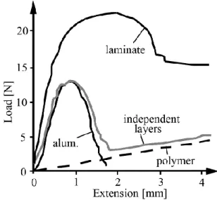
This material was the subject of earlier studies by Kao-Walter et al. (2002). In the experi-mental studies a centre cracked panel geometry was used. Four specimens were compared. These were a single aluminium foil, a single polymer layer and a laminate constructed of these two. The polymer material was a so called LDPE (low density polyethylene). The resulting strength of the laminate was compared with the fracture strength of the individual layers. A remarkable increase of the toughness of the laminate as compared with that of the individual layers, was observed, see Fig. 1.
Fig. 1: Load displacement curves for the laminate, including the result for sheets of aluminium and polymer put together with no interconnection marked ”independent layers”. Included is also the test result for single aluminium foil and a single polymer film.
The stiffness of the polymer layer is only a fraction of that of aluminium at the straining when peak load is reached. Therefore the load carrying capacity obviously has increased dramatically as compared with that of the individual layers. When peak load is reached for the laminate, nominal strains are fairly small and only aluminium is expected to carry any substantial load because of the low stiffness of the polymer. It was somewhat of a surprise that the strength of the laminate was almost twice the strength of the aluminium foil. Improved mechanical properties has been observed and analysed before, e.g. by Macioncyk and Bruckner (1999) and Li et al. (2005). These studies focus on the integrity of the metal film and on structures without initial cracks.
In the present paper, the fracture mechanisms are simulated. The experimental study Kao-Walter et al. (2002) reports that necking seems to precede fracture. In the present analysis a Barenblatt region (cf. Barenblatt, 1962) is simulated in the sense that the local approx-imately plane deformation ahead of the crack tip is considered. This fracture mechanism was observed and analysed by Dugdale (1959). The fracture processes are assumed to be elastic-plastic and localized straining is assumed to continue until the cross section simply vanishes. Therefore, fracture criteria becomes obsolete. The analysis focus on the influence of the adhesion between the layers. Load capacity is computed for the process region of a two-layer laminate specimen as well as for the individual layers of the laminate. The results suggest a possibility for multiple necking that would increase the toughness several magnitudes.
2. THE MODEL
The necking region ahead of a crack tip is considered, see Fig. 2a. A coordinate system, attached to the crack tip, defines the initial position of the necking region as 0 ≤ x ≤ d, |y| ≤ t/2 and |z| ≤ t/2. The considered geometry for this analysis is a cross section initially ahead of x = d. As the crack is growing, the complete development of the cross section is reflected along the x-axis, where time increases in the negative x-direction. The changes along the x-direction is assumed to be small over distances of the order of d. Therefore, the cross section is in an approximate plane strain in the y-z plane. Here plane strain is assumed for the geometry in Fig. 2b. Load is applied in the y-direction. The material is assumed to be elastic-perfectly plastic with the modulus of elasticity E, Poisson’s ratio ν=0.3 and the yield stress σo. The plastic deformation is associated to von Mises’ flow surface.
a
b
Fig. 2: Necking region a) the crack tip and the necking region, b) a cut through the necking region along the y-z plane.
3. ANALYSIS OF THE HOMOGENEOUS CASE
The problem may be solved analytically for a homogeneous material. Fig. 3 shows two snap shots of the states passed through by a cross section through the necking region. The flow rule does not allow for any volumetric plastic strains, i.e. the volume is preserved if elastic straining is assumed to be negligible. The slip occurs along planes forming 45o to the y-axis which leads to slopes of the surface adjacent to the necking region along z = ±y/2 (cf. Hill 1952). The load carried per unit of original thickness, t, of the segment becomes
F = σo(t − vp), (1)
where vp is the plastic part of the displacement across the necking region. If the strip is long compared with its thickness the elastic deformation has to be considered. As a function of the total elongation v of the strip the load becomes
F =
tvE/h for v < σoh/E
σo(t − v)/[1 − σoh/(Et)] for σoh/E ≤ v ≤ t ,
(2)
where h is the original length of the strip. As the elongation of the strip increases, finally the thickness of the cross section vanishes, as also the load. This defines the crack tip.
Fig. 3: Two states of a developing necking region. Loading is in the y-direction. The total plastic elongation is vp.
Slip line solutions may also be constructed for laminated materials but, as far as the present authors understand, without large difficulties only for the initial slipping.
4. NUMERICAL ANALYSIS
For the laminated cases the problem is solved numerically using a commercial finite element code (ABAQUS, 2006). A regular mesh with 850 eight node isoparametric plane strain elements is used to cover a part with height t and length h = 3t. The meshed part was subjected to prescribed displacement at the edges y = ±h. The position of the neck is controlled by a few surface nodes, that are displaced to make the width of the strip locally slightly smaller. To secure the desired position of the neck the width was made 0.999t at the centre of the segment. Some care also had to be taken to avoid necking near the edges where the prescribed displacement is applied.
Figures 4a and b shows the numerical result for aluminium respectively polymer. Included in the figure are also the corresponding analytical results. As observed both results are pretty accurate except for large displacements when the cross sectional area is reduced to and less than around 10 - 20%, or equally when the prescribed displacements are lager than 0.8t to 0.9t. The slightly different results displayed by the two materials has to be contributed to the different ratios of modulus of elasticity versus yield stress. Plastic deformation localize in an initially t times t, quadratic region at the centre of the strip. In the most strained part the elements become very distrorted. When the elongation reaches t, the aspect ratio of the most distorted element has exceeded 10, which makes the results less accurate. Two cases are analysed for the laminate, i.e., in the first case an aluminium foil and an polymer film with a perfectly bonded interface and in the second case the same materials bonded together but with rather brittle interface. The thickness of the aluminium foil is 9 µm and the thickness of the polymer film is 25 µm. To extend the applicability of the results, the thicknesses are normalized with the total thickness t of the laminate. Thus, the thickness 0.265t is used for the aluminium foil and 0.735t is used for the polymer film. For aluminium, the modulus of elasticity is E, Poisson’s ratio ν=0.3 and the yield stress is σo. The modulus of elasticity of the polymer is 0.1E, Poisson’s ratio ν=0.3 and the yield stress is 0.3σo. For the case with a brittle bond the interface is unbonded along a segment with the length equal to the thickness of the aluminium layer, i.e. 0.265t. The aluminium layer is made slightly thinner in the middle of that segment to achieve proper necking.
Fig. 4: Simuleations of homogeneous sheets of aluminium (right) and polymer (left). Analytic solutions (dashed lines) are included for comparison. Note that the scaling of the tensile force is with respect to the yield stress σo for respective material.
In Figs. 5a and b the profile of the plastically deformed geometries obviously depends on the properties of the interface. The elongation of half of the specimen, v=0.5t. Comparison of the two cases shows that the plastic deformation of the polymer is to a large extent controlled by the plasticity of the aluminium layer. In Fig. 5a one observes how the polymer layer is sucked into the void area that is the result of the plastic deformation of the aluminium layer. The aluminium seems less affected by the presence of the polymer layer. As oserved also in Fig. 5b the deformation becomes asymmetric in the polymer film and plastic deformation obviously becomes constrained by the contact with the aluminium foil.
Fig. 5: Deformed geometries of (a) specimen with a perfectly bonded interface and (b) with an interface in which a crack has been introduced over a 0.265t long segment. The upper layer is aluminium.
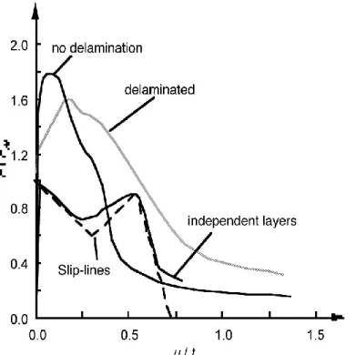
The observed interaction between the two layers also affect the load carrying capacity of the laminate. This is shown in Fig. 6, where the cases for perfectly bonded and brittle interfaces are compared with two totally independent layers. In the latter case the results from single aluminium respectively single LPDE layers have been superimposed at the post-analysis. The analytical result is obtained from (2) applied to parameters for the two layers of the laminate.
The largest force is obtained for the perfectly bonded laminate and is 1.8Fo where Fo is the maximum force carried by the aluminium layer. The force decrease to 1.6Fo for the partly delaminated case and just above Fo for the unbonded layers.
note that no energy is attributed to the delamination process in the present analysis. The brittleness is revealed in Fig. 6 as the area under the curve for perfectly bonded laminate is found to be smaller than the area under the curve for the perfect bond case in the same figure. The area is close to 70% larger for the partly delaminated. The unbonded material requires slightly less energy for fracture than the perfectly bonded laminate.
Fig. 6: Force versus displacement for the perfectly bonded and the partly delaminated materials are compared with to independent layers. The slip-line solution (2) for totally unbonded layers moving without any interaction, is included.
5. DISCUSSION AND CONCLUSIONS
The result presented in Fig. 6 provide a guide for selection and design of desired interface properties. If high strength is sought for a structure without cracks a large peak stress is desired because this is the stress at which cracks can be initiated. Thus, the interface should be made as strong as possible since the perfect bonded interface gives the largest peak force. The peak force is a slightly more than 10% above that for the partly delaminated structure. The reason for the larger peak stress seems to be that the material is forced to large plastic strains in both materials because of the constraint introduced by the undamaged interface. The elastic strain limit is much lower in the aluminium than in the polymer. Therefore, plastic deformation is expected to occur first in the aluminium layer. This introduces large strains also in the polymer layer. Thus, the load carried by the polymer layer increase until its strength limit is reached. This hypothesis is supported by the observation in Fig. 6, that the maximum force is 1.8Fo when this is compared with the force 1.83Fo, obtained by adding the maximum force that may be carried aluminium and the same carried by the polymer.
If the material contains a crack or if a crack is initiated at a notch it is a draw back is that the laminate with the perfectly bonded interface is more brittle than the laminate
that delaminates partly. The, around 70% larger energy needed to fracture the partly delaminated material as compared with the partly bonded laminate implies that the fracture toughness is around 30% larger for the delaminating structure.
The implication for the fracture process region, i.e. the necking region ahead of the crack, is that the linear extent of the region is approximately 70% larger for the delaminating mate-rial. This limits the applicability of linear fracture mechanics to 70% larger minimum crack length as compared with required minimum crack lengths for perfectly bonded laminates. The result for independent layers has the most remarkable implication in the present analy-sis. The focus is set on the observation of two peaks for the force. The particular combination of materials studied here will obtain a single necking region. Once necking is initiated the force never exceeds the value needed for necking again. The process is described as fol-lows: The force increases rapidly as long as both materials are elastic. Once the aluminium becomes plastic the load will decrease until the aluminium layer is broken. The polymer layer is still elastic. Because of that load continues to increase until also this layer become plastic. After this the load decreases under increasing displacements until both layers are broken. The observed behaviour lead us to the heuristic conclusion that a laminate with a slightly higher yield stress or larger thickness of the weaker layer, here the polymer layer, must behave quite different. As the load is increasing towards the second local peak force further loading is interrupted because other parts of the structure now reach loads exceeding the first peak force. Two possibilities are foreseen: multiple necking or a widening necking region. The load will not reach the second, presumably larger peak stress in any part of the structure until the entire laminate structure is plastic. This leads to an almost unlimited increase of the energy absorbed during loading. The two possibilities needs to be evaluated against the impact they have on the aluminium foils oxygen barrier functionality.
ACKNOWLEDGEMENT
Financial support from The Knowledge Foundation under grant no. 2004/0274 is acknowl-edged.
REFERENCES
Barenblatt, G. I. (1962). Advances in Applied Mechanics. 7, 55.
Dugdale, D. S. (1959). Yielding of Steel Sheets Containing Slits. J. Mech. Phys. Solids 8, 100.
Hill R. (1952). On Discontinuous Plastic States, with Special Reference to Localized Necking in Thin Sheets. J. Mech. Phys. Solids 1, 19.
Kao-Walter, S. St˚ahle, P and , H¨agglund, R (2002). Fracture Toughness of a Laminated Composite, in: Fracture of Polymers, Composites and Adhesives II, Elsevier, Oxford, UK, ISBN: 0-08-044195-5, 355.
Macionczyk, F. and Bruckner, W. (1999). Tensile Testing of AlCu Thin Films on polyimide foils. J. Appl. Phys. 86 4922.
Li, T., Huang, Z. Y., Xi, Z. C., Lacour, S. P., Wagner, S., Suo Z. (2005). Delocalizing Strain in a Thin Metal Film on a Polymer Substrate. Mech. Mater 37, 261.
Teng Li and Z. Suo (2007). Ductility of thin metal films on polymer substrates modulated by interfacial adhesion. Int. J. of Solids and Structures 44, 1696.