1
MEASURING TYRE PERFORMANCE IN ESC INTERVENTION
SITUATIONS.
Mattias Hjort
VTI, Swedish National Road and Transport Research Institute Olaus Magnus Väg 35
SE-581 95 Linköping, Sweden mattias.hjort@vti.se
Abstract – Fatal accidents during winter time in Sweden are to a large extent due to vehicle spinning. Therefore,
it is crucial to analyse and compare vehicle/tyre performance on slippery roads with respect to oversteering. We have performed experimental tests to compare the stability performance of various winter tyres on ice, with and without an electronic stability system (ESC). Two different test methods are presented, one closed loop and one open loop test. Results from both studies are discussed, and it is clear that different tyres may have a large impact on vehicle stability even with ESC activated.
1. Backgr
ound
Active safety systems are becoming increasingly common in today’s vehicles. Electronic Stability Control (ESC) systems were introduced during the end of the 1990s, and accident statistics show that they have had a huge impact on traffic safety. Early tests on track have indicated that ESC systems have a great potential at reducing accidents where the driver suddenly lose control over the vehicle (Yamamoto and Kimura 1996). Many studies based on accident statistics confirm that ESC systems have been very effective in reducing the number of single accidents among passenger cars and SUVs. It is estimated that the introduction of ESC has decreased the number of fatal single accidents with 30-50% for passenger cars and between 50-70% for SUVS [1]. Some studies have also found that ESC systems are increasingly effective for wet or icy road conditions [2-4].
The ESC system aims at helping the driver to maintain vehicle stability. This means that the vehicle should follow the drivers intended path without spinning out (over steering) or ploughing straight ahead (under steering). Research has shown that most drivers have problem controlling the vehicle at the limit of its handling capability. This is discussed in [5]. The main design philosophy for the ESC system is that the system should help the driver to keep the vehicle controllable i.e. to avoid excessive vehicle side slip angles. This is achieved by using individual wheel brakes to control the vehicles yaw motion. Since the ESC system is dependent of sufficient available braking forces there is a risk that its performance is strongly coupled to the tyre properties on surfaces with low friction, like ice and snow. Moreover, it is on these surfaces that the difference in road grip is the largest for different types of tyres.
In Sweden the tyre manufacturers distinguish between three different kinds of winter tyres. Studded tyres have always been the tyre offering the least compromises for Nordic conditions with respect to traffic safety, and in general offer very good grip in winter road conditions, paired with good grip on bare roads. If one wants to drive with an unstudded winter tyre there is a choice between those constructed for Nordic conditions, which offer good winter road grip, while the bare road performance is worse, or the unstudded winter tyre of central European type, which in general are worse on ice and snow, but offers very good bare road performance. VTI has conducted two separate studies comparing tyre performance and ESC intervention: one closed loop and one open loop test. The first was a double lane change manoeuvre with 6 different drivers, comparing the performance of 4 different winter tires on ice. The latter study used predefined steering manoeuvres with a steering robot in order to obtain as much oversteering as possible in different icy conditions. This paper will briefly describe the methodology that was used and the main results.
2. Double
lane
change
test
For a closed loop test, which involves the action of a driver, we chose the modified ISO 3888-2 manoeuvre [6] as a starting point. This manoeuvre consists of a double lane change. By driving through the manoeuvre with
2
several test drivers on ice we were able to alter the course layout so that driving through the course at too high speed would result in an oversteer situation. It should be pointed out that understeering during the first lane change was never a problem with any of the tested tyres. This course layout is shown in Figure 1.
Figure 1 Course layout
The highest speed for which the course could be passed without knocking down any of the cones was used as the performance measure. Four different tyres, together with four different passenger cars was tested with and without ESC enabled, which results in 32 combinations. The test was performed in Arjeplog in the northern Sweden. Six test drivers had to drive through the course and each one establish the maximum speed for all the combinations. The test surface was polished ice with a reference friction ranging between 0.135 – 0.165 (measured with a portable friction tester PFT, [7]) during the three days for which the tests were carried out. The ice surface was prepared at the beginning of each test day by performing multiple runs through the course until the friction level remained constant. The relative friction variation during the three days of testing was about 20% and would be too large for an accurate comparison of the tyres if they had been tested in sequence. To handle the friction variations we used a balanced test schedule where all the four tyres were being tested in parallel during the entire test period.
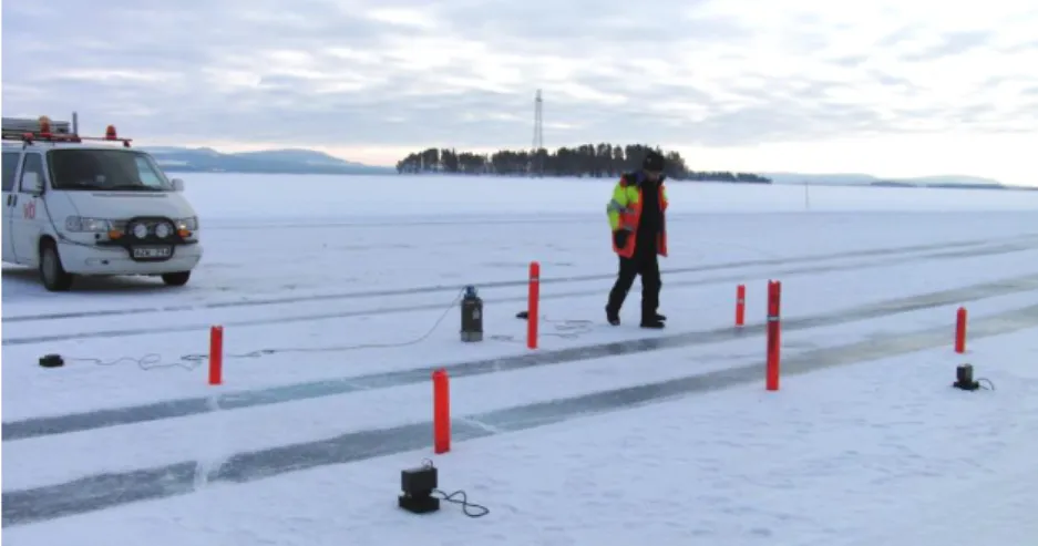
To get an accurate value of the incoming speed, this was measured with a couple of optical sensors positioned at the front gate of the course, see Figure 2, resulting in an accuracy better than 0.2 km/h. By gradually adjusting the entry speed, each driver was able to establish the maximum possible speed at an estimated accuracy of 1-2 km/h
Figure 2 The equipment for measuring the vehicle speed.
For each car/tyre combination a test driver would need about 10 runs to establish the maximum possible speed of the manoeuvre for the case ESC on, and about the same number of runs for ESC off. In total some 2000 test runs were carried out, resulting in 192 measurement values.
The performance of 4 different unstudded winter tyres was tested, one of Nordic type and three of central European type. The results of the statistical analysis can be summarized in Figure 3. The analysis shows that a statistically significant difference in performance exists only between the tyre of Nordic type and those of European type. No statistically significant difference between the tyres of European type could be found. The
3
difference in performance with ESC on and off is statistically significant. However, there was no statistically significant interaction between ESC and tyre, which means that the performance increase with ESC on is about the same, approximately 1 km/h, for all the tyres. This increase can however be regarded as small compared to the performance difference between the two different types of tyres.
Average maximum speed for the tyres with and without ESC
60 61 62 63 64 65 66 67 68 69 70
Tyre 1: Nordic winter tyre
Tyre 2: Central European winter tyre
Tyre 3: Central European winter tyre
Tyre 4: Central European winter tyre
S pe e d (k m /h)
ESC off ESC on
Figure 3 Performance comparison of the tyres
3. Overst
eer test
with
steerin
g robot
The purpose of this study was to develop a test method (limited to steering inputs only) for evaluating a vehicle's stability during oversteering on icy roadways, and to use this method to test how large is the difference between performances of various kinds of winter tyres on ice. To do so, plenty of tests on polished ice and rough ice tracks were performed in northern Sweden with a rear wheel driven car and six different tyres. The description of the test track and the test equipment follows.
The tests were performed at Colmis proving ground in Arjeplog, northern Sweden, on two different test surfaces (see Figure 4):
Rough ice track, 60 m wide and 1500 m long.
Polished ice track. 20 m wide and 150 m long.
Figure 4. Part of the Colmis proving ground in northern Sweden
As on all ice fields, the surface friction changed rapidly based on weather conditions; therefore, reference measures for the surface friction were taken frequently. Another factor that contributed to inconsistency of the
4
surface condition during the tests was the tyre skidding marks left on the track after each manoeuvring, leading to partial polishing of the smooth ice surface.
A Mercedes Benz C200 station wagon was used for all tests. A rear wheel driven car was chosen since it was considered to be more sensitive to oversteering. The tests were performed using a steering robot called ALVTI, jointly developed by VTI and Autoliv [8]. The ALVTI steering robot consists of an electric motor mounted on the steering wheel column which can be decoupled via a magnetic clutch, also enabling normal driving with the robot installed. Vehicle movement and state parameters was recorded with Racelogic Vbox system, which is a GPS based system, measuring vehicle position and speed at 100 Hz. Accelerations and rotations were measured at the same frequency by a tri-axial inertial measurement unit (IMU).
3.1 Method
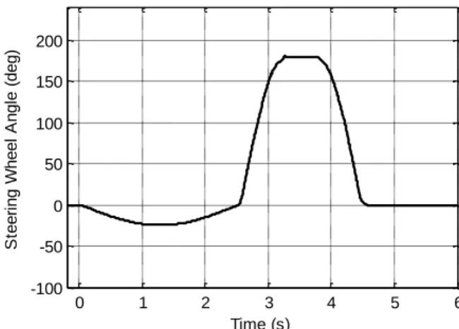
The development of the method is described in detail in [9]. The steering input is an asymmetric sine-with-dwell, with small and slow steering input in the first half of the cycle and large and fast steering inputs in the second half; see Figure 5.
0 1 2 3 4 5 6 -100 -50 0 50 100 150 200 S te e ri n g W h e e l A n g le ( d e g ) Time (s)
Figure 5. Asymmetric steering input for inducing oversteer on icy road surface.
This steering input can be described by four parameters: amplitude (a) and frequency (f) for each half of the cycle; the dwell time was fixed at 0.5 second as in the NHTSA sine-with-dwell manoeuvre. The parameter values for generating maximum amount of oversteer depends on the test track surface, as well as the vehicle, including the tyres. The following procedure was used to decide the manoeuvre parameters:
1. Select the amplitude, a1, and frequency, f1, of the first half of the cycle so that the vehicle is at the verge of
understeering.
2. Use a1 and f1 values selected in step one and decide the amplitude, a2, and frequency, f2, of the second half
of the cycle so that the vehicle oversteers as much as possible.
3. Use a2 and f2 values selected in step two and tune a1 and f1 so that the vehicle oversteers as much as
possible.
To decide the manoeuvre parameters by the described procedure, tests were performed by the vehicle equipped with the tyres which had the worst side grip. Later, the same manoeuvre and parameters were used for all tyres, ensuring that the vehicle will not understeer heavily in the first half of the cycle; since all other tyres had a better grip. The calculated parameters are a1=25 (35) deg, f1=0.2 (0.25) Hz, a2=180 (220) deg, f2=0.35 (0.45) Hz for
the polished (rough) ice track.
3.2 Measures for quantifying oversteering
Oversteering is commonly defined for quasi-stationary circle driving. Consider a vehicle driving in a circle with constant speed. If the vehicle speed increases, the required steer angle for negotiating the same circle may vary. The vehicle is:
Oversteer, if the steer angle should increase with increased speed
Understeer, if the steer angle should decrease with increased speed
Neutralsteer, if the steer angle does not change with increased speed
However, since the purpose of this study is to compare oversteering in a transient and not stationary event. Another approach that can be used for determining the amount of oversteering is to look at the relation between
5
the yaw rate,
, and lateral acceleration, ay. In steady state circular driving at speed v, the entities are relatedas:
v
a
yBased on this, the following classification for a transient manoeuvre was defined:
The vehicle is oversteering if
v
a
y The vehicle is understeering if
v
a
yAdditionally, the relative difference was used as a measure for quantifying the level of oversteering at a certain point: y y o
a
a
v
M
This relative difference is illustrated as a grey area in figures presented below; the integrated grey area was used as a total measure of the oversteer severity of the manoeuvre and is referred to as oversteering factor in the rest of the article. In mathematical terms, the oversteering factor is the integral of Mo over the interval
where
v
a
y, excluding areas wherea
y
0
.
1
m/s2 to avoid too high values of Mo . Normally, there is a time delay between the built up of the yaw rate and lateral acceleration of the vehicle in a transient manoeuvre, which is natural and should not be counted as oversteering. Therefore, the lower time limit for starting integration of Mo was set to the time point where the steering wheel angle reaches 70% of its maximum value.In addition to the oversteering factor, the maximum side slip angle and the time to stability was also used as measure of the vehicle performance. Time to stability was defined as the period between the completion of steering input and the time when the yaw rate and lateral acceleration go back to zero and the vehicle drives in a straight line. Since the manoeuvre induced skidding may last for a long time, it was not always possible to measure the time to stability due to the limited space on the test track.
3.3 Results
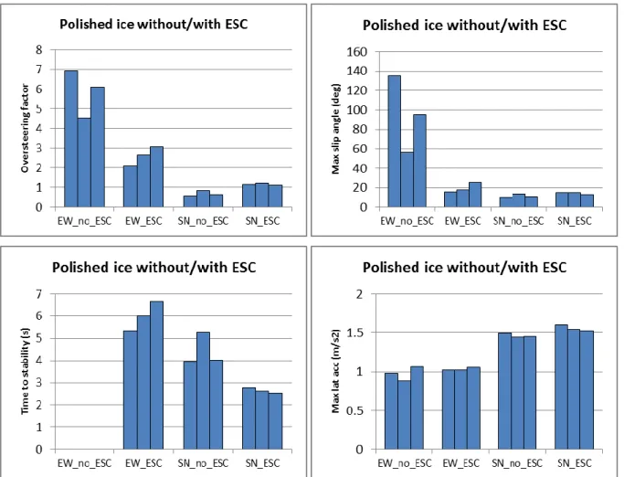
The developed test method was applied to a number of different tirs on the two ice tracks. Some results from the polished ice with two tyres that have very different grip performance, a new studded tyre (denoted SN) and a worn central European unstudded winter tire (denoted EW), are presented below.
The calculated oversteering factor, time to stability and the maximum slip angle for the performed tests on polished ice are depicted in Figure 6. The lateral acceleration is also plotted to show the difference in the vehicle manoeuvrability. It can be seen that all the three use measures show that the vehicle equipped with the studded tyre is more stable and oversteer less than the vehicle with the worn central European tyre. This is despite the fact that the studded tire results in more severe manoeuvre with higher level of lateral acceleration, due to better side grip. In other words both manoeuvrability and stability are better with the studded tyres on polished ice. The ESC improves the vehicle performance considerably when the EW tyres are used. In fact for the EW_no_ESC case, the vehicle does not stabilize at all.
The interesting outcome is that both oversteering factor and maximum side slip angle are higher for the case with the SN tyres when the ESC is on in comparison with the ESC-off case. However the time to stability is improved when ESC is activated. This can be explained by a closer look at the vehicle states during the manoeuvre, see
Fel! Hittar inte referenskälla.. In the beginning of the second half of the cycle, ESC intervenes and speeds up
the yaw rate increase to avoid understeering, which results in an increased oversteering and maximum side slip angle by the end of manoeuvre. On the other hand, ESC also intervenes when the oversteering happens and manages to stabilize the vehicle faster than the case when ESC is off.
All the three used measures, namely oversteering factor, maximum side slip angle and time to stability are larger for the vehicle with the new studded tyres, despite the fact that it has a better side grip. However, the lateral acceleration is also larger for the studded tyres, meaning that the resulted manoeuvre is more severe for the studded tire. It can be concluded that for a fair comparison of various tyre types, the developed method should be modified; for instance, the manoeuvre can be adjusted to result in some lateral displacement or lateral acceleration for all the cases.
6
Figure 6. The calculated performance measures for the tests on the polished ice track
4. Conclu
sion
Tests with both drivers and steering robot show that the manoeuvrability on ice can be heavily influenced on the choice of tyres, even with the aid of an electronic stability system. In fact, in certain situations the difference in performance between tyres are greater that driving with or without ESC. The conclusions that can be made from these kinds of performance tests are not straightforward. We conclude, however, that at a sudden lane change manoeuvre on really slippery road conditions, where the driver is not struck by panic and is able to steer the vehicle without exaggerated steering movements, the road grip performance of the tyres is far more important than the presence of an ESC system.
This does not mean that ESC systems are ineffective on slippery surfaces. On the contrary, accident statistics show that the introduction of ESC in passenger cars has resulted in a sharp reduction in the number of personal injury accidents on slippery roads. It is conceivable that a driver who unexpectedly finds himself in a situation where a manoeuvre similar to the one we tested would have more use of an electronic stability control system than what our results show. Most likely will an unprepared driver in the same situation act in a different way compared to our test driver. One likely driver response is that the driver tries to steer past the first hurdle, but exaggerates the steering which could easily lead to loss of control. In such a situation, an ESC system plays a crucial role in maintaining control and avoiding an accident or, alternatively, reduce the severity of an accident. Experience from previous studies is that it can be difficult to evaluate how drivers act in an unexpected emergency using field tests. For example, VTI, together with Volvo Trucks evaluated how well a driver can handle a tire explosion on a front tire on a truck. Field tests in which the driver was prepared for a tire explosion indicated that the driver could handle the situation while driving simulator studies with completely unprepared drivers showed the opposite, showing the importance of the surprise effect [10].
The two presented methods both have their strengths and weaknesses. The closed loop test has a closer resemblance to a real driving situation, while the robot test allows for better repeatability and steering inputs that
7
allows for more general conclusions. We think that in the future it may be possible to combine the strengths of both methods and perform closed loop tests with steering robots, powered by a driver model.
References
[1] S.A. Ferguson: The effectiveness of Electronic Stability Control in Reducing Real-World Crashes: A
Literature Review. Traffic Injury Prevention,8:4, 329–33, 2007.
[2] A. Lie, C. Tingvall, M. Krafft and A. Kullgren: The Effectiveness of ESP (Electronic Stability Program) in
Reducing Real Life Accidents. Traffic Injury Prevention, 5, 37–41, 2004.
[3] A. Lie, C. Tingvall, M. Krafft and A. Kullgren: The effectiveness of electronic stability control (ESC) in
reducing real life crashes and injuries. Traffic Injury Prevention, 7, 38–43, 2006.
[4] P. Thomas: Crash Involvement Risks of Cars with Electronic Stability Control Systems in Great Britain, International Journal of Vehicle Safety, Vol. 1, 267–281, 2006.
[5] Y. Shibahata, K. Shimada and T. Tomari: Improvement of vehicle maneuverability by direct yaw moment
control. Vehicle System Dynamics, 22, pp 465-481, 1993.
[6 ] National Highway Traffic Safety Administration: Federal Motor Vehicle Safety Standards; Electronic
Stability Control Systems, (Docket No. NHTSA-2006-25801), Department of Transportation, Washington, DC.
2006.
[7] B. Wälivaara: Validation of VTI-PFT version 4. VTI Notat 16-2007, VTI, Linköping, 2007.
[8] http://www.vti.se/en/research-areas/vehicle-technology/test-methology-active-support-systems/alvti/
[9] Hjort M., Bruzelius F., Andersson H. and Kharrazi S.. Towards a method for determining maximum oversteer
in slippery conditions. Proceedings of 23rd International Symposium on Dynamics of Vehicles on Roads and
Tracks (IAVSD’13).Qingdao, China, 2013.
[10] H.E. Pettersson, J. Aurell and S. Normark: Truck driver behaviour in critical situations and the impact of
surprise – a pilot study of a sudden blow-out on the front axle of a heavy truck. Proceeding of the DSC 2006