C RE A SIN G E N ER G Y E FFI C IE N C Y IN E LE C TRI C T R A IN S O P ER A TIO N 2018 ISBN 978-91-7485-409-1 ISSN 1651-4238 Address: P.O. Box 883, SE-721 23 Västerås. Sweden
Address: P.O. Box 325, SE-631 05 Eskilstuna. Sweden E-mail: info@mdh.se Web: www.mdh.se
Driver advisory systems and energy storage
Mälardalen University Press Dissertations No. 275
INCREASING ENERGY EFFICIENCY
IN ELECTRIC TRAINS OPERATION
DRIVER ADVISORY SYSTEMS AND ENERGY STORAGE
Nima Ghaviha
2018
Copyright © Nima Ghaviha, 2018 ISBN 978-91-7485-409-1
ISSN 1651-4238
Mälardalen University Press Dissertations No. 275
INCREASING ENERGY EFFICIENCY IN ELECTRIC TRAINS OPERATION
DRIVER ADVISORY SYSTEMS AND ENERGY STORAGE
Nima Ghaviha
Akademisk avhandling
som för avläggande av teknologie doktorsexamen i energi- och miljöteknik vid Akademin för ekonomi, samhälle och teknik kommer att offentligen försvaras fredagen den 16 november 2018, 13.00 i Pi, Mälardalens högskola, Västerås.
Fakultetsopponent: Professor Rob M.P. Goverde, TU Delft
Abstract
Electric traction is the most efficient traction system in the railway transportation. However, due to the expensive infrastructure and high power demand from the grid, the share of electric trains in the railway transportation is still lower than other trains. Two of the possible solutions to increase the share of electric trains are: optimal train operation to minimize energy consumption, the use of batteries as the energy source for driving electric trains on non-electrified lines. This thesis aims to extend the knowledge in the field of energy optimal operation of electric trains and battery-driven electric trains.
Energy optimal operation of electric trains is supervised using a driver advisory system (DAS), which instructs the driver to operate the train in an energy-efficient manner. This thesis contributes to DAS technology under two topics: the increase of energy efficiency and the design of DAS.
This thesis presents a complete procedure of designing a DAS from the mathematical formulation to application on the train. The designed DAS is in the form of an Android application and is based on a dynamic programming approach. The computational performance of the approach is enhanced using heuristic state reducing rules based on the physical constraints of the system. The application of the DAS shows a potential reduction of 28% in energy consumption.
This thesis considers the detailed energy losses in the whole propulsion system using a regression model that is generated from validated physical models. The application of the regression model instead of a previous constant efficiency factor model results in 2.3% reduction in energy consumption of the optimum speed profiles.
Based on the solution for the normal electric trains, a solution is also offered for the optimal operation of battery-driven electric trains, in which the characteristics of the battery as one of the main components are considered using an electrical model. The solution presented in this thesis, is to combine the popular single mass point train model with an electrical circuit battery model.
Furthermore, this thesis evaluates the performance of the optimization approaches and validates the models against the measurements from actual drives of a real-life battery train. The results show a potential of around 30% reduction in the charge consumption of the battery.
The results of this thesis (algorithms and the Android application) are provided as open source for further research in the field of energy efficient train control.
ISBN 978-91-7485-409-1 ISSN 1651-4238
Acknowledgement
First I would like express my profound gratitude toward my supervisors
Prof. Erik Dahlquist and Prof. Markus Bohlin for their continuous support
during the past years. This research would not have been fruitful without their
guidance and encouragement. My sincere appreciation to Christer Holmberg,
my mentor from Bombardier Transportation; everything I learned in power
en-gineering and electric trains was thanks to his guidance and support. I would
also like to thank my co-supervisor Dr. Fredrik Wallin. I am grateful to
Mag-nus Forsen for providing me with the opportunity to work at Bombardier
dur-ing my PhD and also PPC team at Bombardier Transportation for their help
with this research project, namely: Per Bengtsson, David Lindgren, and Kevin
Babr. I would also like to thank Dr. Helena Jerregård and Dr. Stig Larsson
from RISE SICS Västerås for their support during the STREAM project.
Spe-cial thanks to Dr. Martin Joborn from RISE SICS for the great discussions and
for reviewing this thesis.
I would also like to thank Prof. Kondo from Chiba University that
pro-vided me with the opportunity to work in their lab. Further, I am grateful to
Prof.Konstantinos Kyprianidis for the opportunity to work with him during
the last six months of my PhD studies. Special thanks goes to Dr. Jan
Sand-berg for reviewing this thesis as well as for the great experiences that I gained
during teaching in his courses.
Special thanks to my colleagues and dear friends at EST department for
all the inspirational conversations, coffee breaks and lots of happy memories.
Thanks to my friends outside university, both in Sweden and Iran, that are
very close and dear to me.
Many thanks to Vale for her continuous and unconditional support during
the past year. Last but foremost, much appreciation to my parents and my
brother, I could not have reached this far in life without their endless support
and love.
This research was conducted at the school of Business, Society and
Engi-neering at Mälardalen University, Sweden and was supported financially by
EST department at Mälardalen University, and VINNOVA (2014-04319 and
2012-01277) as a part of STREAM project lead by RISE SICS.
Nima Ghaviha
October 2018
Västerås, Sweden
Summary
Electric traction is the most efficient traction system in the railway
trans-portation. However, due to the expensive infrastructure and high power
de-mand from the grid, the share of electric trains in railway transportation is
still lower than other trains. Two are the possible solutions to increase the
share of electric trains: to optimize electric train operations to minimize the
energy consumption and to use batteries as the energy source for driving
elec-tric trains on non-electrified lines. This thesis aims to extend the knowledge
in the field of energy optimal operation of electric trains and battery-driven
electric trains.
Energy optimal operation of electric trains is supervised using a driver
advi-sory system (DAS), which instructs the driver to operate the train in an
energy-efficient manner. This thesis contributes to DAS technology under two topics:
the increase of energy efficiency and the design of driver advisory systems.
Although there are already DAS systems in use in some railway lines,
there are no clear study on the design procedure of such systems. This thesis
presents the design procedure of a DAS from the mathematical formulations
to the design of the interface. The application of the designed DAS on a real
train shows the promising decrease of 28% in energy consumption.
To increase the energy efficiency in the problem of energy optimal train
op-eration, this thesis goes deep to the component level in the propulsion system
by considering the detailed power losses in each component. The results of
this thesis show that the optimum driving styles generated by considering the
detailed power losses are around 2.3% more energy efficient compared to the
optimum driving styles generated using one constant efficiency factor for the
whole train.
Based on the solution for the normal electric trains, a solution is also
of-fered for the optimal operation of battery-driven electric trains, in which the
characteristics of the battery as one of the main components are considered
using an electrical model. Furthermore, this thesis validates the models and
evaluates the optimization performance against the actual drives of a real-life
battery train. The results show a potential of around 30% reduction in the
charge consumption of the battery.
The results presented in this thesis can be used as a basis for further research
and development in the field of energy optimal operation of electric trains and
battery driven electric trains.
Sammanfattning
Elektriska traktionssystem är de mest effektiva traktionssystemen för
järn-vägsfordon. Pågrund av den kostsamma infrastrukturen och höga krav
på-effekt från elnätet är dock andelen eltåg vid järnvägstransporter fortfarande
lägre än andra tågtyper. Optimering av tågets manövrering för att minimera
energiförbrukningen och användning av batterier som energikälla för att köra
eltäg pä icke-elektrifierade linjer är tvåav lösningarna som kan öka andelen
eltåg vid järnvägstransporter. Den här Avhandlingen syftar till att utöka
kun-skapen inom energioptimering av eltåg och batteridriven eltåg.
Energioptimal drift av eltåg övervakas med hjälp av ett Driver Advisory
System (DAS), vilket är ett system som instruerar föraren att driva tåget
påett energieffektivt sätt. Denna avhandling bidrar till DAS-teknologin inom
tvåområden: ökad energieffektivitet och utformning av DAS.
Även om det finns DAS-system som används påvissa järnvägslinjer
finns det ingen tydlig studie om designproceduren för sådana system.
Den här avhandlingen presenterar designproceduren för en DAS från de
matematiska formuleringarna till utformningen av gränssnittet. Verklig
tillämpningen av den DAS som designats i anslutning till avhandlingsarbetet
visar en lovande minskning av energiförbrukningen med cirka 30%. För
att öka energieffektiviteten i koppling till problemet med energioptimal
tågets manövrering, går denna avhandling pådjupet rörande komponenter
i framdrivningssystemet genom att beakta de detaljerade effektförlusterna
för varje komponent. Resultaten av denna avhandling visar att de optimala
körstilarna som genereras genom att överväga de detaljerade effektförlusterna
är cirka 2,3% mer energieffektiva jämfört med de optimala körstilarna som
genereras med en konstant effektivitetsfaktor för hela tåget.
Baserat pålösningen för nätdrivna eltåg, erbjuder avhandlingen ocksåen
lös-ning för optimal drift av batteridrivna eltåg, där batteriets egenskaper som en
av huvudkomponenterna beaktas med hjälp av en elektrisk modell. Dessutom
validerar denna avhandling modeller och utvärderar den framtagna
optimer-ingsmetoden mot mätningar påett verkligt batteridrivet eltåg. Resultaten visar
potential för cirka 30% minskning av batteriets energiförbrukning.
Resultaten som presenteras i denna avhandling kan användas som
under-lag för vidare forskning och utveckling inom området energioptimal drift av
nätdrivna och batteridrivna eltåg.
List of Papers
This thesis is based on the following papers, which are referred to in the text
by their Roman numerals.
I Ghaviha, N., Bohlin, M., Wallin, F., & Dahlquist, E. (2015,
Novem-ber). Optimal Control of an EMU Using Dynamic Programming and
Tractive Effort as the Control Variable. In Proceedings of the 56th
Con-ference on Simulation and Modelling (SIMS 56), October, 7-9, 2015,
Linköping University, Sweden (No. 119, pp. 377-382). Linköping
Uni-versity Electronic Press.
II Ghaviha, N., Bohlin, M., & Dahlquist, E. (2016, June). Speed profile
optimization of an electric train with on-board energy storage and
con-tinuous tractive effort. In Power Electronics, Electrical Drives,
Automa-tion and MoAutoma-tion (SPEEDAM), 2016 InternaAutoma-tional Symposium on (pp.
639-644). IEEE.
III Ghaviha, N., Campillo, J., Bohlin, M., & Dahlquist, E. (2017). Review
of application of energy storage devices in railway transportation.
En-ergy Procedia, 105, 4561-4568.
IV Ghaviha, N., Holmberg, C., Bohlin, M., & Dahlquist, E. (2017).
Model-ing of Losses in the Motor Converter Module of Electric Multiple Units
for Dynamic Simulation Purposes. Energy Procedia, 142, 2303-2309.
V Ghaviha, N., Bohlin, M., Holmberg, C., Dahlquist, E., Skoglund, R.,
& Jonasson, D. (2017). A driver advisory system with dynamic losses
for passenger electric multiple units. Transportation Research Part C:
Emerging Technologies, 85, 111-130.
VI Ghaviha, N., Bohlin, M., Holmberg, C., Dahlquist, & E. Speed Profile
Optimization of Catenary-free Electric Trains with Lithium-ion
Batter-ies (Manuscript under review)
Reprints were made with permission from the publishers.
Part of this thesis (Papers I and II) was previously included in the
licenti-ate thesis "Energy Optimal Operation of Electric Vehicles: Development of a
driver advisory system" (Ghaviha, 2016).
The following publications by the author are not included in this thesis.
• Ghaviha, N., Wallin, F., Dahlquist, E., & Bohlin, M. (2014, December).
An Algorithm for Optimal Control of An Electrical Multiple Unit.
In Proceedings of the 55th Conference on Simulation and Modelling
(SIMS 55), Modelling, Simulation and Optimization, 21-22 October
2014, Aalborg, Denmark (No. 108, pp. 300-307). Linköping University
Electronic Press.
• Ghaviha, N., Bohlin, M., Wallin, F., & Dahlquist, E. (2015). Optimal
control of an emu using dynamic programming. Energy Procedia, 75,
1913-1919.
• Campillo, J., Ghaviha, N., Zimmerman, N., & Dahlquist, E. (2015,
March). Flow batteries use potential in heavy vehicles. In Electrical
Systems for Aircraft, Railway, Ship Propulsion and Road Vehicles
(ESARS), 2015 International Conference on (pp. 1-6). IEEE.
• Shashaj, A., Bohlin, M., & Ghaviha, N. (2016, June). Joint optimization
of multiple train speed profiles. In Compatibility, Power Electronics
and Power Engineering (CPE-POWERENG), 2016 10th International
Conference on (pp. 478-483). IEEE.
• Campillo, J., Dahlquist, E., Danilov, D. L., Ghaviha, N., Notten, P. H.,
& Zimmerman, N. (2017). Battery Technologies for Transportation
Applications. In Technologies and Applications for Smart
Charg-ing of Electric and Plug-in Hybrid Vehicles (pp. 151-206). SprCharg-inger, Cham.
• Ghaviha, N., Energy Optimal Operation of Battery Driven Trains. ORbit
medlemsblad for Dansk Selskab for Operationsanalyse og Svenska
Opera-tionsanalysföreningen, (2016)
Contents
Page
Part I: Thesis
1 Introduction . . . .
3
1.1 Objective . . . .
4
1.2 Outline of the Thesis . . . .
5
2 Related Works . . . .
7
2.1 Speed Profile Optimization of Electric Multiple Units . . . .
7
2.2 Driver Advisory Systems . . . .
9
2.3 Catenary-free Operation of Electric Multiple Units . . . 10
3 Research Framework . . . 11
3.1 Research Questions . . . 11
3.2 Challenges . . . 11
3.3 Methodology . . . 12
4 Overview of the Papers . . . 14
5 Mathematical Formulation . . . 18
5.1 Train Model . . . 18
5.2 Battery Models . . . 20
5.2.1
Simplified battery model . . . 20
5.2.2
Generic battery model . . . 21
5.3 Dynamic Programming . . . 22
6 Results and Discussion . . . 25
6.1 Energy Optimal Operation of Electric Multiple Units . . . 25
6.1.1
Detailed Power Losses . . . 25
6.1.2
Driver Advisory System . . . 29
6.2 Energy Optimal Operation of Battery Driven Electric Multiple
Units . . . 31
6.2.1
Battery Model . . . 32
6.2.2
Speed Profile Optimization . . . 33
6.3 Discussion . . . 35
6.4 Contribution to Knowledge . . . 38
7 Conclusion . . . 41
8 Future Directions . . . 43
References . . . 45
Part II: Included Articles
List of Figures
Page
Figure 2.1: A speed profile including coasting phases . . . .
8
Figure 4.1: Relation between articles and research questions . . . 17
Figure 5.1: A generic tractive effort curve or the maximum
trac-tive effort available in different velocities of an EMU
(Paper V) . . . 19
Figure 5.2: A typical discharge curve of a lithium-ion battery with
the constant current load. The x axis shows the charge
taken from the battery. . . 21
Figure 5.3: Backward iteration of dynamic programming approach 22
Figure 5.4: Forward simulation of dynamic programming approach 23
Figure 6.1: Applicable tractive efforts at each velocity for a
cer-tain train configuration . . . 26
Figure 6.2: Example of the applied tractive effort points during a
driving cycle (Paper IV) . . . 26
Figure 6.3: Comparison of the loss calculation using a constant
efficiency factor and detailed electrical equations . . . . 27
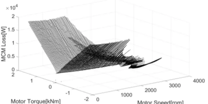
Figure 6.4: MCM power loss for all the points under the tractive
effort curve of a certain electric train configuration
(Paper IV) . . . 28
Figure 6.5: Off-line unit of the driver advisory system (Paper V) . . 30
Figure 6.6: On-line unit of the driver advisory system (Paper V) . . 31
Figure 6.7: Speed profile of an experiment used for the validation
of SoC estimation based on mechanical power
(Pa-per VI) . . . 33
Figure 6.8: Measured state of charge compared with the modeled
state of charge (Paper VI) . . . 34
Figure 6.9: Comparison of the energy consumption between the
experiments and the optimization approach for a trip
of a)3 km and b)6.27 km (Paper VI) . . . 35
Figure 6.10: Comparison between the speed profiles generated
using a constant efficiency factor and the regression
model (Paper V) . . . 36
Figure 6.11: Screen shot of the Android DAS during the operation;
box 1 shows the current speed and box 2 shows the
recommended optimum tractive effort (Paper V) . . . 37
List of Tables
Page
Table 4.1: Research questions and the papers including the answers
16
Table 6.1: Root mean square error of different polynomials for
ac-celeration section (Paper V) . . . 28
Table 6.2: Root mean square error of different polynomials for
Nomenclature
Abbreviations
ATO Automatic Train Operation
C-DAS Connected Driver Advisory System CATO Computer Aided Train Operation DAS Driver Advisory System
DC Direct Current DP Dynamic Programing
EETC Energy Efficient Train Control EMU Electrtic Multiple Unit
IPEMU Independet Powered Electric Multiple Unit LRV Light Rail Vehicle
MCM Motor Converter Module
OESS On-board Energy Storage Systems RAM Random Access Memory
SESS Stationary Energy Storage Systems Symbols
η Efficiency of the propsulsion system [%] ηConverter−Modules Efficiency of the converter module [%]
ηGearbox Efficiency of the gearbox [%]
ηMotor Efficiency of the motor [%]
ˆyi Modeled values [−]
ω Motor speed [rpm]
π∗ Optimum series of control variables [−]
τ Motor torque [Nm]
A Coefficient for the generic battery model [V] Arr Coefficient of Davis Formula [kN]
B Coefficient for the generic battery model [A−1h]
Brr Coefficient of Davis Formula [km/hN ]
Crr Coefficient of Davis Formula [km/h2N ]
E0 Battery open circuit voltage [V]
EAh Charge consumption on battery [Ah]
EkW h Energy consumption on DC Link [kWh]
Emax Maximum energy capacity of the battery [kWh]
Fg Gradient Force [kN]
Ft Tractive Force [kN]
Frr Running Resistance [kN]
fsw Switching frequency [Hz]
g(x,u) Transition cost [−]
h Change in elevation of the track [m] I · T Charge consumed from the battery [Ah]
Ibat Current on the battery [V]
J∗(x) Minimum cost-to-go [−]
Jπ(x) Cost-to-go [−]
K Coefficient for the generic battery model [V Ah]
k Coefficient of the regression model [−]
LossMCM Power loss in MCM [kW]
m Train Mass [m
s]
n Sample size [−]
p Coefficient of the regression model [−] Paux Power consumption of the auxiliary systems [kW]
Ploss Power loss [kW]
Q Maximum charge capacity of the battery [Ah] q Coefficient of the regression model [−] R Internal resistance of the battery [Ω]
r Receptivity of the power grid [−]
RMSE Room mean square error [−]
s Distance traveled [m]
SoC State of charge [−]
T Last time step in the horizon [−]
t Time [h]
u Control variable [−]
v Velocity [ms−1]
Vbat Voltage on the battery [V]
Vgrid Line voltage of the grid [V]
Vsim Line voltage of during the simulation [V]
x State of the system [−]
Part I:
Thesis
1. Introduction
In total, the transportation sector is responsible for 24.7% of the CO2 emissions and 28.8% of energy consumption on the global scale (IEA & UIC, 2017). The railway sector accounts for 4.2% and 1.9% of the share of the whole transport sector in CO2 emissions and energy consumption, respectively (IEA & UIC, 2016). One reason for this low share is the high capacity of railway systems and their high efficiency, which lead to lower emission and energy consumption per passenger and tonne. On the other hand, the share of railway in terms of total trips globally is only 6.9%. The share of passenger trips is even lower, coming after road and aviation with 6.7% (IEA & UIC, 2017). Since the Paris Agreement in 2015, the International Union of Railways has set new goals to increase the share of the railway sector in transportation, while lowering CO2 emissions (75% reduction) and energy consumption (60% reduction) by 2050 (IEA & UIC, 2016).
Reducing emissions and energy consumption involves different fields of research, two of which are the focus of this thesis: efficient train units and energy-efficient train control (EETC) (Scheepmaker, Goverde, & Kroon, 2017).
EETC addresses the problem of controlling a train in order to minimize the energy consumption while keeping to a timetable. This is handled by the driver advisory system (DAS). DAS is a system that instructs a train driver on how to control a train in the most energy-efficient manner. In order to recommend an energy-efficient decision to drivers, the DAS needs to calculate an energy optimum speed profile for each trip. A comprehensive solution to the EETC problem and the resulting recommendation from a DAS should consider different types of constraints such as the followings: train configuration (i.e. braking system, tractive effort curve and power losses in the rolling stock), track profile (i.e. speed limits, curves and gradients), running resistance and the characteristics of the power and train network (i.e. power losses in the grid and the signaling system) (Miyatake & Ko, 2010). The optimum recommendation for a DAS system is the result of an optimization problem called energy-optimal train operation or speed profile optimization. This problem has been studied for many decades and different solutions are offered in the literature (e.g. see (Ichikawa, 1968) for one of the first published studies in this field). Different commercialized driver advisory systems are also already on the market (Panou, Tzieropoulos, & Emery, 2013). However, as most of the products are commercialized, much of the mathematical background and the development process behind designing such systems is not available.
Together with the advancements in the field of energy-optimal train operation, new train unit designs and configurations are also contributing to a more energy-efficient railway system. According to the report by the International Union of Railways, the specific energy consumption and CO2 emission of freight and passenger rail transport have been reduced by more than 50% since 1975 (IEA & UIC, 2017). This reflects improvements as a result of increasing the efficiency of train operation as well as the
3
increase in the efficiency of the rolling stock. One reason for these improvements is the increase in popularity of electric traction and catenary systems at the expense of the diesel traction system. Electric traction systems have a higher efficiency compared to diesel traction. Moreover, modern passenger trains that use the catenary system are often equipped with a regenerative braking system, which converts kinetic energy to electric energy during the braking mode and feeds it back to the power grid. However, although regenerative brakes are currently still not used efficiently due to the low re-ceptivity of the low utilized lines ((Hoffrichter, Miller, Hillmansen, & Roberts, 2012)), the technology is still able to increase efficiency through the inclusion of energy stor-age devices in the traction system of electric and diesel-electric trains (Shibuya & Kondo, 2011) (note that the presented information is on the train level, a more com-prehensive study would include the whole energy supply chain, from the source to the wheel, also known as the well-to-wheel analysis (Hoffrichter et al., 2012)). There is, however, a financial barrier to the use of electric traction and overhead lines. The installation cost for 1 km of electrified railway line can be on the order of a million Euros, and there are also yearly maintenance costs (Baumgartner, 2001). Hence, al-though in some countries, such as Sweden, Italy and Korea, around 80% of lines are electrified, the share of electrified lines globally is only around 30% (IEA & UIC, 2017). Catenary-free operated electric trains with on-board energy storage devices are another potential replacement for diesel electric trains; they provide the advantages of electric traction on non-electrified lines while minimizing emissions.
Catenary-free operated electric trains are currently mostly in the prototype phase. Catenary-free light rail vehicles (LRV), due to their low weight and short journey dis-tances, are mostly equipped with supercapacitors as the energy storage device (Becker & Dammig, 2016). For electric multiple units (EMUs) with higher mass and longer travel distances, storage devices with higher energy and power capacity are needed. The current concepts presented for catenary-free EMUs consist of a limited number of EMUs equipped with lithium-ion batteries and hydrogen fuel cells (Campillo et al., 2017; Alstom, 2016). Since the technology of catenary-free operated EMUs is still in its early phase, not much research is being done in the field of speed profile optimization for such trains. The limited research in this field focuses on LRVs using supercapacitors as the energy storage device (Miyatake & Matsuda, 2008).
1.1 Objective
The EETC problem has been studied for several decades. Scheepmaker et. al present a review of different methods and solutions for energy-efficient timetabling and train control (Scheepmaker et al., 2017). Panou et. al. assess the different driver advisory systems on the market (Panou et al., 2013). On the basis of current developments in the field of energy-efficient train operation, the following issues have been identified as knowledge gaps for the problem of energy-efficient single train operation:
• Almost all the research presented in the literature for speed profile optimization or energy-optimal operation of EMUs uses a constant efficiency factor for calculation of power losses in the propulsion system. The only exception is the research pre-sented by Franke et. al. (Franke, Terwiesch, & Meyer, 2000). Nevertheless, there are no studies on the effects of detailed loss calculations on the final results.
4
• Although many driver advisory systems are already on the market, there are no significant publications on the development of a driver advisory system, the vali-dation of such a system and the challenges that accompany it.
• The subject of energy-optimal train operation is well-studied, but the problem of energy-efficient operation of catenary-free EMUs is a new topic in the literature as well as the industry. Most of the research in this field considers a supercapacitor as the energy storage device. Supercapacitors are, however, used mostly for catenary-free operated LRVs. The main energy storage device used for inter-city regional EMUs is lithium-ion batteries. A comprehensive energy-optimal driving regimen for EMUs should consider the characteristics of lithium-ion batteries and their effects on the optimum speed profile (Miyatake & Ko, 2010).
• Alongside the mathematical formulations and optimization techniques for energy-optimal catenary-free operation of EMUs, an experimental evaluation of the results is needed. This includes validation of the models and the potential energy savings that can be achieved using energy-optimal driving regimens.
It should be noted that the focus of this research is on the EETC problem for EMUs. Unlike locomotive-hauled trains, EMUs do not use locomotives, and have one or more traction systems in the same cars that carry the passengers or goods. The problem is different than that in freight and heavy haul trains, as the different train scale and configuration, together with the longer journeys lead to different constraints in the op-timization problem. Moreover, the focus of this research is on single train operation. Consideration of the whole train network adds new dimensions to the optimization problem, such as losses in the grid and modeling of the receptivity of the line. Fur-thermore, the problem of energy-efficient timetabling is not in the scope of this work. Considering the knowledge gaps, the main contributions of this thesis are as follows: 1. Consideration of detailed power losses in the problem of energy-efficient train
control
2. Development of a DAS for EMUs as an Android application
3. Offering a solution for the problem of energy-efficient control of catenary-free electric trains
4. Studying the effects of properties of the energy storage system on the results of speed profile optimization for catenary-free electric trains
5. Presenting potential energy saving achievable through energy optimal operation for catenary-free operated EMUs
1.2 Outline of the Thesis
The outline and structure of this thesis is as follows: Chapter 2 Related Work
This chapter presents a summary of the current state of the art of the EETC problem for EMUs and catenary-free EMUs. The chapter includes three sec-tions, each dedicated to the literature review of a topic: speed profile optimiza-tion of EMUs, driver advisory system and catenary-free operaoptimiza-tion of EMUs. Chapter 3 Research Framework
This chapter presents the research framework of this thesis. It includes the pre-sentation of the research questions and the methodology used to address each question.
Chapter 4 Overview of the Papers
A summary of the included papers is presented. The chapter also includes a presentation of how the papers relate to the research questions.
Chapter 5 Mathematical Formulation
Mathematical models and the theoretical background of the optimization ap-proach are presented in this chapter. The chapter starts with the presentation of the train model and continues with the battery models used in the problem of speed profile optimization of battery driven trains. The chapter ends with a pre-sentation of dynamic programing approach and its application for the problem of speed profile optimization and energy efficient train control.
Chapter 6 Results and Discussion
This chapter presents the major results of this research. The chapter is divided into two sections: results regarding the EETC for EMUs and results on the EETC for catenary-free operated EMUs. Chapter 6 ends with a discussion on the contribution of this thesis in the form of answers to the research questions. Chapter 7 Conclusion
This chapter presents the overall conclusions of the thesis. Chapter 8 Future Directions
The thesis ends with a short discussion on the possible future directions of the research in the field of energy-efficient train control.
The included articles are appended in the second part of the thesis.
2. Related Works
The problem of energy-optimal train operation has been studied for more than 60 years, and many mathematical solutions have been presented. A number of applied solutions and commercialized driver advisory systems have also been presented dur-ing the recent years. An overall literature review of the solutions is presented here, organized in three sections: speed profile optimization of EMUs, DAS and catenary-free operation of EMUs.
2.1 Speed Profile Optimization of Electric Multiple
Units
The problems of optimal control and speed profile optimization of trains have been studied for many decades, with one of the first studies dating back to 1968 (Ichikawa, 1968). Two approaches have been used to solve the problem: coast control and optimal control. In terms of the operation scale, the problem can be addressed for a single train operation or multiple train operation on a network of trains. Furthermore, regarding train configuration, three categories of are considered for the problem with EMUs: EMUs operating under catenary, EMUs operated under catenary with a secondary energy storage device, and catenary-free operated EMUs.
In coast control the speed profile of the train is considered as one or multiple coast-ing phases durcoast-ing which the applied tractive effort from the traction motor is zero and the train moves under the influence of its kinetic energy. Figure 2.1 presents a speed profile including the coasting phases. The problem aims to find the optimum coasting gaps during operation to minimize the total energy consumption while keeping to the timetable.
Genetic and evolutionary based algorithms are the most common approaches pre-sented in the literature for the coast control problem (see e.g. (Chang & Sim, 1997; Lechelle & Mouneimne, 2010; Erchao, Xin, & Yi, 2014; Bocharnikov, Tobias, & Roberts, 2010; Wong & Ho, 2004) for single train operation and (X. Yang, Chen, Li, Ning, & Tang, 2015) for multiple train operation). Acikbas et. al. (Acikbas & Soyle-mez, 2008) apply the genetic algorithm together with an artificial neural network to solve the coast control problem for a network of trains. The problem for single train operation has also been solved using an artificial neural network (Hui-Jen, Chao-Shun, Chia-Hung, Ching-Ho, & Chin-Yin, 2008). Other approaches such as heuristic search methods (Wong & Ho, 2004) and dual heuristic programming (Sheu & Lin, 2011; Jih-Wen & Wei-Song, 2012) have also been applied to the coast control problem.
The problem of speed profile optimization can also be viewed as an optimal control problem in which the optimum speed profile is determined regardless of coasting or cruising phases. Different solutions, such as ant colony optimization and fuzzy
con-7
Figure 2.1: A speed profile including coasting phases
trol (Yasunobu, Miyamoto, & Ihara, 1983) and reinforcement learning (Yin, Chen, & Li, 2014), have been suggested for the optimum speed profile. Howlett (Howlett, 2000) presents a general formulation of the problem for trains with both continuous and discrete control and solves the problem using the Pontryagin maximum princi-ple with the objective function of minimizing the fuel consumption for trains under continuous control and uses the Kuhn-Tucker equation for diesel-electric locomotives with notched control. Shuai et. al. (Shuai, Xiang, Tao, & Ziyou, 2013) also use the Pontroyagin maximum principle to optimize the timetable of subway trains based on energy-efficient operation. Liu and Golovitcher (Liu & Golovitcher, 2003) use the maximum principle for energy-optimal operation of rail vehicles. Both Liu and Golowitcher, and Shuai et. al. minimize the mechanical power consumption as the objective function. Miyatake and Ko formulate a problem for two train (Miyatake & Ko, 2007b) and multiple train (Miyatake & Ko, 2007a) operation with the objective function of minimizing the electrical power of the trains with a DC power feeding circuit, using the gradient method. Wang and Goverde study the speed profile opti-mization considering the multi train operations and operational constraints (Wang & Goverde, 2016, 2017a). Using the results of the speed profile optimization, Wang also studies the problem of energy efficient timetabling for multi-train operation (Pengling Wang, 2017).
Ko et. al. (Ko, Koseki, & Miyatake, 2004) present an algorithm based on Bellman’s dynamic programming approach for speed profile optimization of EMUs with discrete control variable. The same principle (DP) is used to solve different variants of the speed profile optimization problem (e.g. multiple train operation (Tang, Wang, & Pe, 2014), variable efficiency (Franke et al., 2000) and fast DP with the consideration of passage points (Haahr, Pisinger, & Sabbaghian, 2017)).
Most of the research presented in this section assumes the same mass point train model with constant efficiency. Although there is theoretical research that assumes
8
variable efficiency (e.g. (Cheng & Howlett, 1993)), Liu and Golovitcher argue that including variable efficiency makes the problem and solutions too complicated for practical applications and that constant efficiency is sufficient (Liu & Golovitcher, 2003).
Franke et. al. (Franke et al., 2000) examined the variable loss by using a lookup table of pre-calculated loss values. Additionally, they reconfigured the standard for-mulation for the train energy-optimal control problem by using the kinetic energy per mass unit as one of the dimensions of the state variable, arguing that the new formu-lation reduces the nonlinearities of the problem.
Scheepmaker et. al. provide a review of different approaches used for the problem of energy efficient train control (Scheepmaker et al., 2017).
2.2 Driver Advisory Systems
In order to use the results of the speed profile optimization for minimizing energy consumption, a DAS needs to be developed based on the mathematical formulation. A DAS is a system that presents instructions to the driver regarding how to drive the train based on the solutions of the speed profile optimization or scheduling problem. Different DAS systems are already on the market with instructions based on off-line precalculated speed profiles or on-line optimization. Panou et. al. (Panou et al., 2013) provides a list of major DAS systems on the market and evaluates them on different aspects such as intelligence, user interface and communication.
There are two areas of research relating to designing a DAS: the mathematical so-lution and the implementation of the mathematical soso-lution in the form of a DAS on the train. Most research in this field is focused on the mathematical formulation of the problem and the optimization approaches, and there is little published research on the implementation procedure or mathematical background of the currently avail-able DAS systems. Exceptions are GreenSpeed by Cubris (Haahr et al., 2017), En-ergymiser by TTG Transportation Technology (A. R. Albrecht, Howlett, Pudney, & Vu, 2013) and ETO (Wang & Goverde, 2017b), for which the mathematical solution behind the DAS systems are available in the literature.
Regarding the design and interface, the procedure may vary for different mathe-matical solutions. Zhu et. al. (Zhu, Sun, Chen, Gao, & Dong, 2016) present design of a DAS based on a genetic algorithm approach. Wang and Goverde (Wang & Goverde, 2017a) present their approach of designing a DAS based on their mathematical so-lution. Yang et. al. (L. Yang, Liden, & Leander, 2013) discuss their experiences of deploying a CATO DAS, including the human/machine interaction.
According to Panou et. al. (Panou et al., 2013), a complete implementation of a driver advisory system should tackle three issues: drivers’ needs, machine/human in-teraction and technology compliance. Drivers’ needs presents the priorities for the drivers and their needs, machine/human interaction considers the facilitation of using the DAS and technology compliance focuses on the adaptability of the technology to the current standard technologies (e.g. signaling systems and ERTMS/ETCS1) (Panou
et al., 2013). Moreover, to get the best efficiency out of a DAS, it should be connected to the train control centers and constantly updated by the train network timetable
in-1European Rail Traffic Management System/European Train Control System
formation. A DAS that is connected to the train control center is called a connected driver advisory system (C-DAS). A C-DAS should provide instructions for energy efficient train control considering the railway network traffic and timetable. As an ex-ample, CATO is the only C-DAS in Sweden and one of the first ones developed in the world. There are already projects going on in Europe to provide standard protocols for DAS and C-DAS (e.g. SFERA Project).
2.3 Catenary-free Operation of Electric Multiple Units
Catenary-free operated EMUs are EMUs that can run without overhead lines. These are mostly hybrid EMUs that work both under catenary and without catenary, us-ing an energy storage system. The energy storage system can either be superca-pacitor, battery or fuel-cell based. Supercapacitors are mostly used for catenary-free LRVs (Becker & Dammig, 2016), whereas among the few recent cases of long dis-tance catenary-free medium sized EMUs, two use lithium ion batteries (Campillo et al., 2017; Kono, Shiraki, Yokoyama, & Furuta, 2014) and one is equipped with fuel cells (Alstom, 2016). There has also been an experiment with a prototype LRV that uses hydrogen fuel cells as the power source (Yoneyama, Yamamoto, Kondo, Furuya, & Ogawa, 2007). Batteries and fuel cells, compared to supercapacitors, have a dis-advantage with respect to life cycle and cost. Thus, there have also been theoretical studies on hybrid energy storage solutions for EMUs (Tsukahara & Kondo, 2013).
Because of the immaturity of the technology, most of the research on speed pro-file optimization of catenary-free operated EMUs is focused on LRVs equipped with supercapacitors (see e.g. (Miyatake & Matsuda, 2008) for a solution based on DP and (Colak, Czarkowski, & de Leon, 2012) for a solution for the coast control prob-lem). The solution presented in (Miyatake & Matsuda, 2008) and (Colak et al., 2012) cannot be applied to the problem of catenary-free operated EMUs with lithium-ion or fuel cells on board, as in both solutions, voltage of the supercapacitor is a determining factor and is used in the objective function and state variable. The only research in the field of EETC for catenary-free operated EMUs equipped with batteries is presented by Noda and Miyatake (Noda & Miyatake, 2016), who consider the characteristics of the battery using a fitted function from the battery discharge curve.
A well-formulated speed profile optimization solution for battery driven trains should consider the characteristics of the batteries. In general, three types of models used to monitor the performance of lithium-ion batteries have the potential to be used for train applications: mathematical, electro-chemical and electrical equivalent circuit network models. Electrochemical models are complex physics-based models that es-timate the behavior of the battery based on electrochemical equations. Mathematical models model the battery using analytical methods and empirical formulas (Shafiei, Momeni, & Williamson, 2011). Electrical models simulate battery behavior by using electrical circuit components. Among the three categories, electrical circuit models avoid the complexities of high-fidelity electro-chemical models while providing suffi-cient accuracy for the problem of speed profile optimization (Fotouhi, Auger, Propp, Longo, & Wild, 2016). According to Fotouhi et. al., a comprehensive battery model should consider four characteristics of a battery: state of charge, temperature, rate of current and state of health (Fotouhi et al., 2016).
3. Research Framework
This chapter starts with the definition of the research questions. The chapter continues with the challenges for achieving the thesis objectives and answering the research questions. The approach used to tackle each research question is discussed in the last section of this chapter.
3.1 Research Questions
Based on the defined objectives and related works presented in the previous chapter, two main areas of research are considered for this thesis and two research questions are presented for each research area:
I Energy-optimal operation of EMUs
1. What is the procedure for designing a DAS from a theoretical solution? 2. How can we increase the accuracy of the power loss calculation for the
prob-lem of speed profile optimization and other similar applications? II Energy-optimal operation of catenary-free operated EMUs
1. What are the main energy storage devices used for catenary-free operated EMUs, and what model is suitable for the speed profile optimization? 2. How can a dynamic programming approach be used for speed profile
opti-mization of catenary-free operated EMUs considering the characteristics of the energy storage device, and what is the effectiveness of this approach?
3.2 Challenges
There are different challenges on the way of achieving the objectives of this thesis and to answer the research questions.
A DAS should be able to provide an optimal instruction during the operation and with the consideration of the fact that drivers might not follow the exact instruction. In other words, a DAS should be able to provide the optimum speed profile of any state during the operation in near real-time and the calculation time on the train should be minimum. Moreover, a newly developed DAS should be adaptable with the previous technologies and train configurations.
Speed profile optimization of electric trains are often done using the single mass point train model that models the mechanical power of the train. An efficiency factor is usually used in this model to consider the power losses of the propulsion system and train. However, detailed physical models based on electrical equations are needed to calculate accurate power loss values. For instance, losses in motor can be divided into different categories: iron loss, copper loss and mechanical loss (Zhang, Shi, Zhao,
11
& Wu, 2017). The same issue is also observed for the energy storage modeling. De-tailed electrochemical models that provide a deDe-tailed estimation of the energy storage behavior are too complex for the applications that need fast simulation. Moreover, electrical models are also based on electrical equations. The main challenge in this regard is to incorporate a more accurate model of the power losses and behavior of energy storage device in the single mass point train model.
3.3 Methodology
To answer research questions I.1 and I.2, a DAS was designed based on development of the mathematical solution to the application on the train. For this purpose, an op-timization approach and a train model were selected. Dynamic programming (DP) was used as the optimization technique, as it provides a global solution to the optimal control problem and has proved to be a reliable approach in theory (see e.g. (Franke et al., 2000) and (Haahr et al., 2017)). Moreover, the single mass point train model is used to model the train performance. This model, while being simple, provides an overall view of the mechanical power consumption, and has therefore been widely used for the problem of speed profile optimization. Panou et. al. notes that portable devices such as smartphones have the potential to be used for the interface of future driver advisory systems (Panou et al., 2013). The DAS was developed as an Android application for smartphones, because current smartphones are capable of providing enough information for the DAS. Furthermore, to answer research question I.2. and to improve the power loss calculations for the speed profile optimization and dynamic simulation, a regression model is used in place of constant efficiency. In order to test the reliability and speed of DP, the DAS was tested for a specific train and and line section. The case studied for this purpose was a Bombardier Regina EMU and the line section was a part of the Mälaren double track line in Sweden.
Research question II.1 is answered by a review on the application of energy stor-age devices in the railway sector. As a result of the review, batteries are recognized as one of the two main types of energy storage device used in catenary-free operation. Research question II.1 is further answered by incorporating the energy storage char-acteristics using a battery model in the popular mass point train model used in speed profile optimization. By including the battery model in the train model, state of charge of the energy storage device is estimated based on the mechanical power.
Electrical circuit models are identified as a suitable model to model the behav-ior of the battery for speed profile optimization. This type of model is less complex than other battery models, and provides acceptable accuracy. Moreover, electrical cir-cuit battery models have previously been successfully applied to electric and hybrid electric road vehicles. Two battery models that were previously used and validated for electric vehicles and hybrid electric vehicles are studied for this purpose. To an-swer research question II.2, the same DP-based approach used for the design of the DAS is adapted for catenary-free operated EMUs. The effectiveness of the approach is presented in the form of the potential energy saving compared to experimental mea-surements from a battery driven EMU during catenary-free operation. The case stud-ied for the catenary-free EMUs is the Bombardier IPEMU battery train. The IPEMU
train was a prototype battery-driven EMU designed by Bombardier Transportation and tested on a line section in the UK.
4. Overview of the Papers
This chapter presents an overview of each included paper together with a clarification of my contributions. The chapter ends with a presentation of the relation between each of the research questions and the papers.
• Paper I: Optimal Control of an EMU using Dynamic Programming and Tractive Effort as the Control Variable (Ghaviha, Bohlin, Wallin, & Dahlquist, 2015) Built upon the solution offered by Gkortzas for the train operation on a level track with no speed limits (Gkortzas, 2013), this paper offers a solution for the speed profile optimization of electric trains on a non-level track and considering the local speed limits. The approach presented in this paper considers the tractive effort as the control variable. The paper continues with a discussion on a comparison of this approach with using change in the velocity as the control variable and concludes with a suggestion on the suitable approach for each type of train.
• Paper II: Speed Profile Optimization of an Electric Train with On-board Energy Storage and Continuous Tractive Effort (Ghaviha, Bohlin, & Dahlquist, 2016) This paper presents the first solution for speed profile optimization of catenary-free operated EMUs for trains with continuous tractive effort control instead of the notch system. The objective function used in the approach presented in this paper was to minimize the power consumption from the energy storage device. The storage device was assumed to be connected directly to the DC link. The characteristics of the storage device were not considered in this paper. The solution was tested through simulation of a trip on a line section in the UK. Results of this paper show that dynamic programming with change in the velocity as the control variable can be used to design a DAS for catenary-free operated electric trains. This paper also includes a short study on the environmental effects of using a catenary-free operated EMU instead of a similar sized diesel EMU.
• Paper III: Review of Application of Energy Storage Devices in Railway Transporta-tion (Ghaviha, Campillo, Bohlin, & Dahlquist, 2017)
In this paper I studied the application of three types of energy storage device in railway systems: supercapacitors, flywheels and batteries. The main application of these energy storage devices in railways is to harvest energy from regenerative brakes for later use, and consequently, to increase the efficiency of the whole system. The paper also includes the more recent application of energy storage systems in railway: catenary-free operation of electric trains. Two categories of energy storage systems were recognized in this study: stationary energy storage systems and on-board energy storage systems. The paper also includes a brief discussion on two main challenges in the application of energy storage systems.
14
Results of this paper show that catenary-free LRVs are mostly equipped with supercapacitors, whereas among the three storage systems, batteries are the main energy storage systems used for catenary-free EMUs.
• Paper IV: Modeling of Losses in the Motor Converter Module of Electric Multiple Units for Dynamic Simulation Purposes (Ghaviha, Holmberg, Bohlin, & Dahlquist, 2017)
Speed profile optimization and EETC is not the only field in which the detailed calculation of losses is a challenge. In this paper I studied the detailed calculation of losses in the motor converter module of EMUs for mechanical power simulation purposes. In the mechanical simulation, power is represented by tractive effort times velocity, considering the efficiency of the whole propulsion system from the wheels to the power source (overhead lines or the energy storage device). The mechanical simulation gives an overall view of the energy consumption during a driving cycle. This paper presents a regression model generated from a validated and detailed electrical model to calculate the power losses in the motor converter module. I further studied the model for three train configurations and twenty-seven experiments. The results show that the presented model can provide a better estimation of power losses than using constant efficiency.
• Paper V: A driver advisory system with dynamic losses for passenger electric mul-tiple units (Ghaviha, Bohlin, et al., 2017)
This paper studies the process of designing a DAS based on dynamic programming. The same approach presented in the previous papers is used as the optimization approach. A main challenge in the energy-efficient train control problem is to obtain a detailed calculation of losses while keeping the calculation time to a minimum (Scheepmaker et al., 2017). Hence, this paper focuses on two main challenges of designing a DAS using dynamic programming: offline calculation time and the accuracy of energy calculations. The calculation time is minimized using heuristic state reducing rules and the accuracy of energy calculations is increased by using a regression model instead of a constant efficiency factor. The paper continues with a description of the process of designing a DAS as an Android application for smartphones. The DAS was tested on a line section of the Mälaren line in Sweden (Kolbäck - Västerås). The results show a significant improvement in energy calculations compared to previous approaches as well as a significant potential in energy saving compared to the current train control regimen in operation on this line section.
• Paper VI: Speed profile Optimization of Catenary-free Electric Trains with Lithium-ion Batteries, Nima Ghaviha, Markus Bohlin, Christer Holmberg, Erik Dahlquist
Much of the research done in the field of EETC for catenary-free operated electric trains considers a light rail vehicle with supercapacitors as the energy storage de-vice. In this paper I study the energy-efficient control of EMUs with lithium-ion batteries as the energy storage device. Two battery models are studied for the speed profile optimization: a simplified battery model and a dynamic battery model. The
15
optimization technique is the same as the one presented in paper II, with a new objective function: minimizing the charge taken from the batteries. Both battery models are validated using the measured values from the test runs of a battery driven EMU prototype designed by Bombardier. The results show that the sim-plified battery model can provide enough accuracy for the purpose of speed pro-file optimization. I further present the potential energy saving achievable through dynamic programming and show the improvements achieved as a result of this problem formulation.
Each research question is addressed by one or more of the appended articles. Ta-ble 4 presents the research questions and the corresponding articles.
Table 4.1: Research questions and the pa-pers including the answers
Research Question Article Research Question I.1 Paper I & V Research Question I.2 Paper IV & V Research Question II.1 Paper III & VI Research Question II.2 Paper II & VI
Paper I presents a basic dynamic programming approach. The approach is fur-ther developed in Paper V and adjusted for designing a DAS considering the detailed power losses. The approach presented in Paper V for the consideration of power losses is used in Paper IV to study power losses in the motor converter module during me-chanical power simulation. The dynamic programming approach in Paper I is also adjusted for catenary-free operation in Paper II. Paper III reviews the application of the energy storage devices for the catenary-free operation. Based on the results of Paper II and Paper III, Paper VI offers a solution for the speed profile optimization catenary-free operated EMUs considering the energy storage characteristics. Figure 4 shows the relation between articles and research questions.
The author was the main contributer in all the papers and did all the studies and simulations under the supervision and with the feedback from the supervisors. In Paper III, Javier Campillo contributed to the description of the three energy stor-age technologies and technical discussions. The electrical modeling and studies in Papers IV, V and VI where done with the help of the coauthor Christer Holmberg. Robert Skoglund and Daniel Jonasson, coauthors of Paper V, were the contributers to the development of the Android application.
Figure 4.1: Relation between articles and research questions
5. Mathematical Formulation
This chapter includes an introduction to the models and the optimization technique used in this thesis.
5.1 Train Model
The focus of this research is on energy-optimal operation of EMUs, which are smaller in size than freight trains. This type of train can be represented by a single mass point model ((A. Albrecht, Howlett, Pudney, Vu, & Zhou, 2016)), which has been widely used for this purpose in the literature (see e.g. (Howlett, 2000)). This section describes the single mass point model used in this thesis.
We assume that the train has mass m and velocity v at time t; acceleration is dv dt, the
running resistance is Frrand the gradient force applicable on the slope is Fg. Further,
Ft is the tractive/braking force needed to move the train that is provided from the
traction motor. Equation 5.1 shows the force balance of the train during operation: m ·dvdt =Ft− Frr− Fg (5.1)
The running resistance is calculated using the Davis formula, which is widely used to calculate the rolling resistance and aerodynamic resistance (A. Albrecht et al., 2016). Equation 5.2 presents the Davis formula:
Frr=Arr+Brr· v +Crr· v2, (5.2)
where Arr, Brr and Crr are constants based on the train configuration. Coefficients
may be determined experimentally or based on physical models, and are dependent on the track geometry and train specifications. The gradient force is calculated using equation 5.3:
Fg=m ·1000h , (5.3)
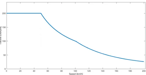
where h is the change in elevation for every 1000 m travelled, and1000h is therefore the estimated sine of the track slope. There is a limitation on the maximum tractive force available from the traction motor. Figure 5.1 shows the maximum available tractive force at different velocities, also known as the tractive effort curve.
The tractive effort curve is designed based on the acceleration and deceleration rate on a level track with no speed limits and is limited by the maximum torque available from the traction motor, the maximum power from the propulsion system and the
Figure 5.1: A generic tractive effort curve or the maximum tractive effort available in different velocities of an EMU (Paper V)
out torque of the induction motor (Paper V). The tractive effort curve is not designed for a specific line voltage and can be used within a range of line voltages.
The power consumption of the EMU is calculated using equation 5.4:
P = r · (Ft· v + Ploss) +Paux, (5.4)
where P is the total power consumption and Paux is the power consumption of the
auxiliary system, which is assumed to be constant. The train is equipped with re-generative brake systems and it is assumed that when the train is in braking mode, the kinetic energy is converted to electrical energy and transmitted back to the power grid. Receptivity of the line during regenerative braking is represented by r and is assumed to be constant. r is equal to 1 during acceleration. In the case of the battery driven EMU, the power consumption P is calculated as the power of the battery:
Vbat· Ibat =Ft· v + Paux+Ploss, (5.5)
where Vbat and Ibat are the voltage and current from the battery. Plossrepresents the
losses in the propulsion system, comprised of three main losses: gearbox loss, motor loss and converter loss. Ploss is usually calculated using a constant efficiency factor.
Hence, equation 5.4 is rewritten as equation 5.6: P = 1 η· (Ft· v) + PAux if Ft>0 η· r · (Ft· v) + PAux otherwise, (5.6) where η is the efficiency of the whole propulsion system, which is the product of the efficiency of different components, as presented in equation 5.7:
η= ηGearbox· ηMotor· ηConverter−Modules (5.7)
η is the efficiency of the whole propulsion system from the wheels to the power source, ηGearboxis the efficiency of the gearbox, ηMotoris the efficiency of the motor
and ηConverter−Modulesrepresents the efficiency of the converter modules. Besides the three mentioned losses, there are other minor losses that are negligible compared to the other three. The efficiency of each component however, is not constant in practice and varies with the velocity and the applied tractive effort.
5.2 Battery Models
Among the different types of battery models, electrical models are most suitable for power and dynamic simulations and they have been used for different transportation applications (Mousavi G. & Nikdel, 2014). Although electrochemical models are the most accurate model type, they are based on detailed electrochemical and differential equations and are too complex for dynamic simulation purposes.
Two electrical circuit equivalent battery models were studied for this research: the simplified battery model and the generic battery model. Both these models can be used for different types of batteries (Fotouhi et al., 2016). The few design variables of both models can be estimated from the manufacturer’s data sheets, making the models easy to use (Tremblay & Dessaint, 2009). As well as transportation applications, the two battery models have also been used for several other purposes, such as wind power generation (Puleston, Valenciaga, Battaiotto, & Mantz, 2000) and DC micro grid systems (Xu & Chen, 2011). Generic characteristics of these battery models that make them applicable for batteries with different chemistries and their ease of use makes them a suitable option for the speed profile optimization application.
The simplified battery model models the terminal voltage as a function of current, whereas the generic battery model models the terminal voltage based on both current and state of charge. State of charge in both models is calculated using equations 5.8 (also known as the Coulomb Counting method (Rivera-Barrera, Muñoz-Galeano, & Sarmiento-Maldonado, 2017)):
dSoC dt =−
Ibat· dt
Q (5.8)
where Ibat is the current, dSoCdt is the derivative of state of charge over time, t is the
time in h, SoC is the state of charge and Q is the total battery capacity in Ah.
5.2.1 Simplified battery model
In the simplified battery model, the battery is modeled as a voltage source and an internal resistance (Johnson, 2002). Thus, the battery voltage depends on the current. Vbat=E0− Ibat· R, (5.9)
where E0is the battery constant voltage value and R is its internal resistance. Further,
Vbat is the voltage of the battery.
5.2.2 Generic battery model
The generic battery model is a more detailed version of the simplified battery model which considers the current state of charge in the model:
Vbat−dischr=E0− R · Ibat− K · ( Q Q − I ·t)· (I ·t + I∗) +A · exp(−B · I ·t) (5.10) Vbat−chr=E0− R · Ibat− K · ( Q I ·t − 0.1 · Q)· I∗− Q Q − I ·t· I ·t + A · exp(−B · I ·t), (5.11) where Vbat−dischr and Vbat−chr are the battery voltage during discharge and charge, respectively. Q is the battery capacity, I is the battery current and t is the time passed. I ·t represents the integral of the total charge taken from the battery which is calculated based on the state of charge. Further, I∗is the filtered current, which can be assumed
to be equal to the current (Tremblay & Dessaint, 2009). The constants A in V, B in (Ah)−1 and K in V
Ah are taken from the discharge curve of the battery ((Tremblay,
Dessaint, & Dekkiche, 2007; Tremblay & Dessaint, 2009)). Assume Figure 5.2 is the discharge curve of a lithium-ion battery.
Figure 5.2: A typical discharge curve of a lithium-ion battery with the constant current load. The x axis shows the charge taken from the battery.
Coefficients of A, B and K are extracted using equations 5.12, 5.13 and 5.14 (Tremblay et al., 2007; Tremblay & Dessaint, 2009):
A = Vf ull−Vexp (5.12)
B = 3
Qexp (5.13)
K =(Vf ull−Vnom+Aexp(−B · Qnom− 1)) · (Q − Qnom)
Qnom , (5.14)
where Vexp and Qexp are the voltage and battery capacity at Point A, and Vnom and
Qnomare the voltage and capacity at Point B, depicted in Figure 5.2. Further, Vf ull
represents the maximum voltage of the battery under load.
5.3 Dynamic Programming
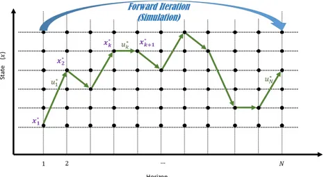
Dynamic programming is selected as the optimization technique for this study. It is an effective optimization technique that has been previously used for the speed profile optimization and trajectory optimization (see e.g. (Franke et al., 2000) and (Haahr et al., 2017)). It has also been used for other application such as the trajectory optimiza-tion of heavy vehicles ((Hellström, Åslund, & Nielsen, 2010)) and aircrafts ((Menon & Park, 2016)). Moreover, application of DP will ensure the fast response time dur-ing the operation. Dynamic programmdur-ing is a two stage process: backward iteration or optimization and forward iteration or simulation. Figures 5.3 and 5.4 present the two stages of dynamic programming.
Figure 5.3: Backward iteration of dynamic programming approach
Three variables are needed for a dynamic programming solution: state variable (i.e. x), control variable (i.e. u) and independent variable, which represent the optimization horizon. Dynamics of the system is recognized using equation 5.15 and the three variables of state, control and horizon:
xi,k+1= f (xk,ui), (5.15)
meaning that the next state in the horizon after state xk is determined according to
the applied control variable (i.e. ui). Transition cost g(xk,ui) is defined as the cost
when control variable uiis applied to the state variable xk. The aim is to get from the
initial state x0 to the final state xN, following a series of control and state variables
that minimize the total cost. If π is a series of control variables that can be applied to state xk(π = uk, ...,uN−1), the total cost-to-go of applying π to state xkis calculated
Figure 5.4: Forward simulation of dynamic programming approach using equation 5.16: Jπ(xk) = N−1
∑
i=k g(xi,ui) +gN(xN), (5.16)where Jπ(xk)is the total cost-to-go and gN(xN)is the cost at the terminal state xN. The
problem is therefore to find the value of π∗that minimizes the total cost-to-go, which
can be written as equation 5.17: J∗(xk) =min π N−1
∑
i=k g(xi,ui) +gN(xN) (5.17)If J∗(xk+1)is known for all the values of states in the step k + 1 in the horizon,
equation 5.17 can be rewritten as equation 5.18, : J∗(xk) =min
ui {g(xk,ui) +J
∗(xi,k+1)}, (5.18)
where xi,k+1is calculated using equation 5.15. Further, u∗is declared as the control
variable that minimizes the right-hand side of equation 5.18. If gN(xN)is known, the
optimum control variable for all the states in the horizon can be found by backward iteration in the horizon and using equation 5.18 (Figure 5.3). Having the optimum decision at all the states, by forward simulation in the horizon from any state, the optimum series of states and control variables can be found (Figure 5.4)(Papers V and I).
In this dissertation, and for the problem of speed profile optimization of both nor-mal EMUs and catenary-free EMUs, time t is assumed as the horizon and T repre-sents the last step in the horizon. In case of the normal EMU, the state of the system