State Politics, Water Supply, and Systems Engineering
Ed Weaver
Department of Systems Engineering, Colorado State University
Abstract. Tarrant Regional Water District (TRWD) was established in 1924 with two primary
missions – flood control and water supply in and around Tarrant County, Texas. TRWD’s current 11 county service area population of 1.8 million is projected to be 2.25 million by 2050.
Sustainability will be key in meeting these growing demands. In 1997, the 75th Texas Legislature passed Senate Bill 1 aimed at improving development and management of the state’s water resources by establishing a regional water planning process. In terms of systems engineering doctrines, Texas basically established a state wide water resources super system or system of systems and provided the associated concept development stage process for the state’s designated planning regions to execute on an iterative and recurring five year cycle. With respect to
sustainability, Senate Bill 1 also directed that water conservation options and actions be integral to the water supply planning, permitting and operational developments. Part of TRWD’s sustainable water supply is a 2,000 acre constructed wetlands put online in 2013. This paper examines
TRWD’s constructed wetlands from the systems engineering and sustainability perspectives. From the systems engineering standpoint, the Richland Chambers (RC) Wetlands Facility was designed and constructed using a multi-phased prototype approach allowing TRWD to research and evaluate treatment performance, operation and maintenance issues, and design criteria through actual field trials and implementation. The RC Constructed Wetland meets the State’s conservation
(sustainability) requirement in that the developed indirect reuse system successfully treats and enhances the quality of the Trinity River return flows from TRWD’s service area prior to
discharging back into Richland Chambers Reservoir for the return trip to the service area. The net achievement is adding the equivalent of a new source to TRWD’s water supply inventory without building a new reservoir or transmission conveyance (system capacity upgrade), achieving the State required conservation (recycling) mandate in Senate Bill 1 with indirect reuse, and maintaining the existing environmental water quality in Richland Chambers Reservoir with the removal of nutrients and sediments.
1.
Introduction and Background
Some portion of Texas has experienced severe drought during each decade over the last century. In Texas, water availability has always influenced patterns of settlement, and communities grew where water was plentiful. But as many communities grew and prospered, they outpaced their water supplies, making it increasingly crucial to make efficient use of local water resources, to work cooperatively to produce regional water problem solutions, and to move water around the state as necessary to meet the needs of all communities and interests.
Texas’ population growth rate over the past decade is in the range of 1,100 citizens per day, making Texas one of the fastest growing states in the country. By 2060, the Texas population is projected to expand to around 46 million or more people. This combination of rapid progress, robust economy, and susceptibility to drought, makes water supply a critical issue. Therefore it is imperative that the state implement water infrastructure and
water management strategies to avoid at best and to minimize at worst serious social, economic, and environmental consequences in the large urbanized regions as well as the vast rural areas of the state.
When the first state water plan was published in 1961, the population of Texas was around 9.6 million residents, less than half the population of 2012. At the time of the first plan was adopted, 79 percent of the communities in Texas acquired their water needs from groundwater sources. In 2012 there were over 25 million Texans with the population becoming older, less rural, and more diverse. Today most of the populations in the state acquire their water supplies from surface water sources (rivers and lakes), combined with new supplies from reuse and desalination. Ground water is still viable but most demands are met by surface supplies. While a lot has changed since the first water plan, much remains the same. All or part of the state is often too wet or too dry, and planning for times of drought is every bit as relevant today as it has ever been.
The concept for a dedicated water planning agency came about as a result of the worst drought in Texas recorded history. The drought encompassed the entire state beginning in 1950 and ending in 1956 with all but one of Texas’ 254 counties classified as disaster areas. And typical of Texas weather patterns, the drought was broken in 1957 with
torrential rains that flooded every major river and tributary in the state. This drought is still the driest seven-year period in the state’s recorded history and is still considered the “drought of record” for Texas and is the basis for the majority of water supply planning in the state today. The 1996 drought was relatively short in duration but severe enough to prompt and prioritize the importance of state wide water supply planning. Texas is currently experiencing a statewide severe drought that may have the potential to set a new drought of record.
In 1997 the75th Texas Legislature passed Senate Bill 1 aimed at improving development and management of the state’s water resources by establishing a regional water planning process. The Texas Water Development Board (TWDB) was charged with implementing the new water planning legislation and process. The TWDB divided the state into 16 planning regions and established regulations governing the regional planning efforts -- Figure 1. Each water supply planning region is responsible for providing its own planning group that is in charge of developing their respective water plans on a five year recurring cycle.
25
Figure 1. Texas’ 16 regional water supply planning areas.
(Texas Water Development Board -- Water for Texas 2102 State Water Plan)
The Senate Bill 1 regional planning process comprises10 tasks – 1. Describing and evaluating the regional water planning area.
2. Quantifying current and projected populations and water demands over incremental 50-year planning periods.
3. Evaluating and quantifying current water supplies. 4. Identifying water surpluses and needs.
5. Evaluating and recommending water management strategies.
6. Evaluating impacts of water management strategies on water quality.
7. Determining that the plans are consistent in protecting the state’s water, agricultural and natural resources.
8. Recommending regulatory, administrative, and legislative changes. 9. Identifying water management strategies financing plans and options. 10. Adopting and managing the recurring five year plan.
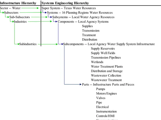
The net effect of the regional planning effort is that it encourages, almost mandates, the regional entities to work together in maximizing the efficient and effective use of the region’s collective water resources and infrastructure and the associated finances. There are also several instances of inter-region sharing and inter-basin transfer arrangements. In terms of systems engineering doctrines, Texas, through Senate Bill 1 and the TWDB, has established a state wide water resources super system or system of systems and provided the associated concept development stage process for the 16 regional planning regions to execute on an iterative and recurring five year cycle – Figure 2.
Figure 2. Texas’ conceptual water resource’s system hierarchy.
Fundamentally, the 16 planning regions perform the needs analyses, concept explorations, and concept definitions (concept developments) that are ratified by the TWDB and then passed to the local water supply agencies for the engineering development and post development stages.
2.
Systems Engineering Life Cycle
The concept development stage for evaluating water conservation and reuse is a subtask of Senate Bill 1, Task 5 above and one that is being actively pursued in Region C by Tarrant Regional Water District (TRWD). Region C’s 16 counties are among the fastest growing areas in Texas since the 1950s. The region’s greatest population density is in Tarrant and Dallas Counties – specifically the cities of Fort Worth and Dallas. Beginning in the 1980s the population growth began to expand into Collin, Denton, Rockwall and Ellis counties. TRWD was established in 1924 with two primary missions – flood control and water supply in and around Tarrant County. On the flood control side, TRWD owns and
Infrastructure Hierarchy
Sector -- Water Super System -- Texas Water Resources
Subsectors Systems -- 16 Planning Regions Water Resources Sub-Subsectors Subsystems -- Local Water Agency Resources Industries Components -- Local Agency Systems
SuppliesSupplies TransmissionTransmission TreatmentTreatment DistributionDistribution
Subindustries Subcomponents -- Local Agency Water Supply System Infrastructure Supply Reservoirs
Supply Well Fields Transmission Pipelines Wetlands
Water Treatment Plants Distribution and Storage Wastewater Collection Wastewater Treatment Parts -- Infrastructure Parts and Pieces
Pumps Motors/Engines Valves Pipe Electrical Instrumentation Controls/HMI Communications
27
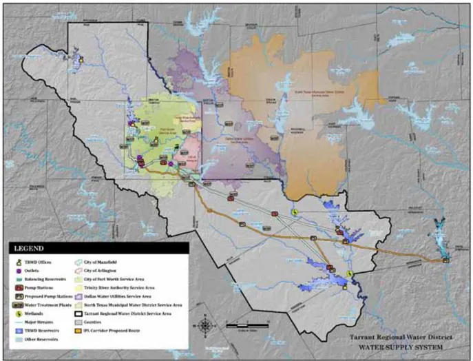
operates a 27-mile floodway levee system along the Trinity River West Fork and Clear Fork branches and controlled release spillways at each of the supply reservoirs that work to provide flood protection for area residents. For water supply, TRWD owns and operates four major supply reservoirs, roughly 150 miles of water transmission pipelines (800-mgd), and a 2,000-acre wetland water reuse facility. TRWD serves around 1.7 million people in an 11-county area in north central Texas through 30 wholesale water customers – Figure 3. TRWD only supplies raw water to the wholesale customers – the wholesale customers perform all treatment and distribution functions.
Figure 3. Tarrant Regional Water District service area.
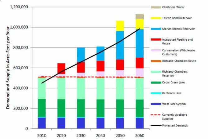
The population growth and associated water demand in TRWD’s service area (mostly Fort Worth and Tarrant County, Texas) from the current 1.7 million to about 2.25 million by 2050, is causing and will continue to cause, increased demands on the water supply
system. The Cedar Creek and Richland Chambers systems currently supply approximately 60 to 70-percent of the demand and will increase to roughly 80-percent by 2020 – Figure 4.
Figure 4. Tarrant Regional Water District current and future demand projections.
In order to meet the projected future water demands, TRWD is pursuing several options. One of these options, pursuant to Task 5, is the diversion of Trinity River water into TRWD’s downstream Richland Chambers and Cedar Creek reservoirs to increase their supplemental yield without the need for additional reservoir or conveyance construction. Water reuse involves the use of groundwater or surface water that has already been beneficially spent. The terms “reclaimed water,” “reused water,” and “recycled water” are employed synonymously in the water supply world. Texas Water Code defines water reuse as reclaimed water from domestic or municipal wastewater that has been treated to a quality suitable for beneficial use – waste water treatment. Two types of water reuse are generally applied: direct reuse and indirect reuse. Direct reuse, as the name implies, is the direct application of reclaimed water from waste water treatment facilities via dedicated pipelines, storage tanks, and other necessary infrastructure -- for example, irrigation of golf courses, parks, and municipal landscaping. Indirect reuse is the use of treated waste water plant effluent that is placed back into a water supply source to be recycled. Water reuse has been growing steadily in Texas over the past two decades as evidenced by the number of applied for permits – from one permit in 1990 to 187 permits in 2010. The concept for the Richland-Chambers Wetland is an indirect reuse system and was developed to enhance the quality of the Trinity River return flows from the TRWD’s service area prior to
29 2.1. Systems Engineering Prototyping.
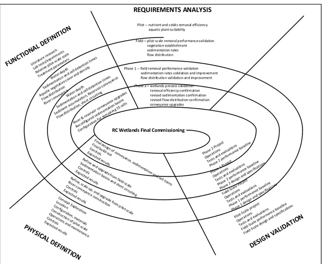
The Richland Chambers (RC) Wetlands Facility was designed and constructed using a multi-phased approach (prototypes) allowing TRWD to research and to evaluate operation and maintenance issues, treatment performance, and design criteria through actual field trials and implementation. From a systems engineering life cycle perspective, the wetlands project was an iterative cycle from needs analysis through to operations support applied through three series of scaled prototype projects – the Pilot Scale Wetlands, the Field Scale Wetlands, the Phase 1 Wetlands Expansion and finally the Phase 2 Wetlands Expansion projects. Each iteration built on the previous cycle’s needs, experiences and, lessons learned (results or outcomes) as depicted in Figure 5.
Pilot -- nutrient and solids removal efficiency aquatic plant suitability Field – pilot-scale removal performance validation vegetation establishment sedimentation rates flow distribution Phase 1 -- field removal performance validation sedimentation rates validation and improvement flow distribution validation and improvement Phase 2 – wetlands process validation removal efficiency confirmation revised sedimentation confirmation revised flow distribution confirmation conveyance upgrades RC Wetlands Final Commissioning REQUIREMENTS ANALYSIS
Figure 5. RC Wetlands Project prototype life cycle model.
These results then became the basis for, and employed in, the final RC Wetlands concept (concept development), performance requirements, specifications, and design (engineering development), and construction, operation and maintenance (post development) system engineering life cycle stages. In short, the wetlands project was the systems engineering life cycle process applied to a series of scaled prototype project models from which the results were used to articulate the final operational design and project execution – each successive project expansion was based on the results of the previous prototype results.
2.2. Pilot Scale Wetlands
The Richland-Chambers Wetland Pilot Scale started with concept development and engineering development through integration and evaluation, followed by construction, and 8 years of operation (1992-2000) that enabled development of information regarding the operational aspects and treatment effectiveness of a constructed wetland system within the proposed context of the Trinity River floodplain. The primary objective of the Pilot Scale system was to develop data to determine the effectiveness and operating
requirements for treating water diverted from the Trinity River to be introduced into the TRWD’s reservoirs without degradation of the receiving water supply.
The Pilot Scale system was designed for a flow rate of 0.1 million gallons per day (MGD), and consisted of two settling basins followed by three parallel wetland trains with each train containing three wetland cells in series as shown in Figure 6.
Figure 6. Layout for constructed RC Pilot Scale Wetlands.
(TRWD and Alan Plummer Associates -- Pilot Scale Constructed Wetlands Summary Report)
The design enabled multiple operational scenarios that could be evaluated concurrently as well as the ability of routing flows so that individual cells or trains could be taken off-line for maintenance (solids removal and wetlands plant vegetation health). Following eight years of pilot scale operation and study, it was determined that the system could achieve target levels for nutrient (nitrogen and phosphorus) and sediment (total suspended solids) removal that would protect water quality within the reservoir as based on comparisons with reservoir tributary inflows. Percent mass removed for sediment was on the order of 95-percent, 82-percent for nitrogen and 66-percent for phosphorus. Testing for heavy metals and toxic organics yielded no detectable indications in the pretreated water or
sedimentation accumulations. Founded on the conclusions from the Pilot-Scale study, TRWD elected to proceed with the construction of the larger Field-Scale wetland system. Related to systems engineering, the prototype pilot scale wetlands project validated the proposed concept definition of water reuse as a means for expanding water resource capacity – the wetland process can/will work.
31 2.3. Field-Scale Wetlands.
Here, the results from the Pilot Scale project became the basis for the Field Scale
performance requirements and design – the Pilot Scale results were fed back to the Field Scale needs analysis phase and the systems engineering life cycle was reinitiated for the second iteration. The Field-Scale wetland system was designed and constructed as the first train of the proposed full-scale system as shown in upper portion of Figure 7.
Figure 7. Layout for the constructed RC Field Scale and Phase 1 Wetlands.
(TRWD, Alan Plummer and Associates, and CH2MHill – Wetlands Commissioning Document)
Development of this initial train with cells at full-scale size enabled further enhancement of the data needed to verify the treatment efficiency exhibited at the Pilot Scale system while testing operational and management requirements and refinement of design criteria. The field scale project consisted of the Trinity River intake pump station (15 MGD), transmission pipeline, one sedimentation basin, and four wetland cells in series totaling about 243 acres along with required distribution canals constructed to allow isolation of any one cell for maintenance or management purposes. The initial 3.5 years of Field-Scale wetland operations included combined periods of start-up and restart-up as well as periods of relatively extended operations when treatment equilibrium representative of long-term performance might be expected. As a result substantial information was developed regarding cell design, construction, planting needs, and operational limitations that were applied to the design criteria for full build-out of the Richland Chambers Wetland. The primary lessons from the field scale project were –
2.2.1. Flow cell short-circuiting relative to cell configuration inlets, outlets, and hydraulic
2.2.2. Native vegetation plant species will take over but are, or can be, just as effective for
reuse water treatment (nutrient consumption).
2.2.3. Additional volume for sedimentation basins was required for settled sediment
volumes.
Treatment performance for the field scale prototype was similar for sediment at 96-percent but dropped to 67-percent for nitrogen and 44-percent for phosphorus. The sedimentation detention time’s repeated similar results but the wetland cell hydraulics and vegetation required additional testing. Again, no evident results for heavy metals or toxic organics.
2.4. Phase 1 Expansion
Construction of the Phase I Wetland Expansion project was initiated in May 2006 and completed in early 2009. The Phase I Wetland Expansion project involved the construction of a second wetland treatment train that parallels the Field-Scale wetland train. This second train included the addition of a second sedimentation basin and approximately 190 acres divided between two wetland cells operated in series, lower portion of Figure 7. The re-lift pump station was constructed to deliver the wetland treated flow into Richland Chambers Reservoir. The Re-lift pump station structure was designed for an ultimate capacity up to 110 MGD. From the Field Scale lessons learned, major changes were incorporated into the design of the wetland cells, including deep water zones located at the inlet, outlet and mid-point of the cells to prevent short circuit flows and detention times. Fine-graded marsh areas were sloped to improve the hydraulic performance of the cells and
corresponding treatment effectiveness. Additional sedimentation basins were enlarged and reconfigured for sludge volume and additional dentition time. Phase 1 treatment results improved from Field Scale phase but not back to Pilot Scale results and still good on heavy metals and toxic organics. Again, results from the previous prototype wetlands project were incorporated and tested prior to moving to the next expansion – performing the advanced development, engineering design, and integration and evaluation phases loop for the full wetlands build-out.
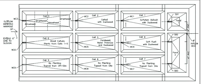
2.5. Phase 2 Expansion
Construction of the Phase II Wetland Expansion Project was initiated in 2010 and
completed in 2013. The Phase II Wetland Expansion Project involved full build-out (110 MGD) of the Richland-Chambers Wetland as shown in Figure 8.
33
Figure 8. Layout for the constructed RC Phase 2 Wetlands.
(TRWD, Alan Plummer and Associates, and CH2MHill – Wetlands Commissioning Document)
Work included pump additions at the river and re-lift pump stations, additional and reconfigured sedimentation basins, wetland trains, flow control structures, flow distribution canals, treated water conveyance canals, roadways and parking areas, and instrumentation for the wetlands. A total of three additional sedimentation basins and fifteen additional wetland cells were constructed, bringing the total wetland footprint to 2,022 acres. The final Wetlands Project is comprised of a river intake and pump station located on the Trinity River where it conveys water through two parallel raw water pipelines that discharge into a combination of five different sedimentation basins. Water flows from the sedimentation basins through pipes or culverts into the head of parallel wetland trains (each train is made up of multiple wetland cells) either directly or via settled water canals. Water is collected from each train and transported to the re-lift pump station where it is pumped over the dam and discharged into Richland Chambers Reservoir.
3.
Cost
The RC Wetlands added 110 million gallons per day or 65,000 acre/feet per year of yield to TRWD’s water supply system (1-acre/foot = 325,828.8 gallons). Collectively, the engineering and construction costs for the three prototype phases (Pilot, Field and Phase 1) and the RC Wetlands build-out was on the order of $75-million. Design and construction for a comparable surface water source would be around $150-million to $250-million based on an equivalent distance from the demand point.
4.
Conclusions and Summary
The Richland Chambers Wetlands Facility is an important component in TRWD’s and Region C’s water supply system and plans. The project diverts Trinity River water, which mostly consists of treated wastewater return flows from the Fort Worth Dallas metro area, into the Richland Chambers Reservoir to provide a supplemental raw water supply. The concept of treating waste water effluent by utilizing aquatic plants to remove nutrients and sentiment (process concept development) for indirect reuse and receiving source water quality was validated with the pilot and field scale wetland projects (process engineering development and post development). Subsequent development of the Phase 1 and 2
Expansions prototypes was focused on applying the lessons learned from the pilot and field scale projects – Figure 9.
Figure 9. Richland Chambers Wetlands Facility final configuration.
(Tarrant Regional Water District, Alan Plummer and Associates, and CH2MHill – Wetlands Commissioning Document)
The Richland Chambers Wetlands project is currently achieving the following objectives –
4.1. Meeting state required conservation requirements by recycling (indirect reuse)
TRWD’s and the Region’s permitted and controlled water resources (system performance upgrade). Conservation efforts are mandated by Senate Bill 1. Basically, water flows from the Richland Chambers Reservoir, to water treatment, to the distribution system and customer use, to waste water treatment, down the Trinity River where it is picked up and processed through the RC wetlands, and finally transferred back into the reservoir for the completed recycled loop.
4.2. Meeting projected demands by adding the equivalent of a new source to TRWD’s and
Region C’s water resources and systems without building a new reservoir or transmission conveyance (system capacity upgrade). As a result of the pilot and field wetlands
prototype projects, TRWD is able to meet medium term demands by building out the entire wetlands facility to supplement the capacity of the existing Richland Chambers supply and conveyance components (modularity, interfaces and interdependencies).
4.3. Maintaining the environmental water quality of Richland Chambers Reservoir by the
removal of nutrients and sediment from the diverted river water as it flows through the wetlands.
4.4. Another feature is that the constructed wetlands are located in the actual Trinity River
bottom to pose no environmental impediments or impacts during flood plain events (designed and intended to flood when the Trinity is out of its banks). Sediment build-up and aquatic plant species were considered in the conceptual, pilot and field-scale phases. Based on these prototypes, the constructed wetlands are comprised of interconnected trains that allow for individual sedimentation ponds and wetland cells to be taken off line for cleaning and/or replanting. When sedimentation or biomass removal is required, the wetlands can be reconfigured with laydown baffle or inflatable gates that keep the system in operation while the ponds are maintained. In the event of a flood, all gates are opened allowing the flood event to pass over the wetlands unobstructed.
Systems Engineering discipline asserts that development of component production process should proceed as their own respective systems engineering life cycle. The same is, or could be true for system component prototypes. A prototype can be a preliminary scaled or full size model, or actual beta production item of an interface, part, subcomponent or component, that involves physical and/or unproven technology issues, to be tested and validated (correcting deficiencies) prior to full scale engineering. The component prototype development process that occurs within the engineering design and integration and evaluation phases, also lends itself to the application of the systems engineering life cycle model. Each prototype cycle involves the concept, engineering, and post
development stages, or in a sense, a sub-systems-engineering-life-cycle model. That is, for a given prototype development the system engineering life cycle is applied to the prototype itself. Based on TRWD identifiable demand needs, concepts were explored, defined, developed, designed, evaluated, produced, and reevaluated during operations of each of the RC Wetlands prototype iterations. The results and lessons learned then became the
foundation starting point for the next prototype project cycle and the final project – Figure 10.
Figure 10. Completed and operational Richland Chambers Wetlands Facility.
The Richland Chambers (RC) Wetlands Facility was designed and constructed using this multi-phased prototype approach allowing TRWD to research and evaluate treatment performance, operation and maintenance issues, and design criteria through actual field trials and implementation. The net achievement is adding the equivalent of a new source to TRWD’s water supply inventory to address projected demands without building a new reservoir or transmission conveyance (system capacity upgrade), achieving the State required conservation (recycling) mandate in Senate Bill 1 with indirect reuse, and
maintaining the existing environmental water quality in Richland Chambers Reservoir with the removal of nutrients and sediments, Figure 7. In addition, the wetlands project is in partnership with the Texas Parks and Wildlife as a public park, education, and recreation area and wildlife sanctuary. The wetlands project has become a haven for migratory birds. The RC Wetlands project has been so successful that TRWD is planning a second
constructed wetlands project to supplement the Cedar Creek Reservoir. The Cedar Creek Wetlands will supply an additional 90,000 to 100,000 acre/feet annually when put on line in roughly 10 to 20 years.
References
Buhman, D., Ickert, R., and Brashear, R. 2014. “Tarrant Regional Water District Integrated Water Supply Plan.” CDMSmith in association with Buhman and Associates, and Freese and Nichols.
Kossiakoff, A., and W. N. Sweet. 2003. Systems Engineering Principles and Practice. Hoboken, NJ (US) Wiley.
Pinto, J. K. 2013. Project Management Achieving Competitive Advantage, Third Edition. Boston, MA (US) Pearson.
37
Tarrant Regional Water District, 2002. “Pilot-Scale Constructed Wetlands Demonstration Project – Comprehensive Report 1993-2000.” Alan Plummer Associates, Inc.
Tarrant Regional Water District, 2008. “Field-Scale Wetlands Phase 1 Operational Period June 2003 to January 2007 -- Final Report.” Alan Plummer Associates, Inc.
Tarrant Regional Water District, 2014. “George W. Shannon Wetlands Recycling Facility at Richland Chambers Reservoir – Project Commissioning Document.” Alan Plummer Associates, Inc., and CH2MHill.
Texas Senate Bill 1 Regional Water Planning for Region C (North Texas), 2010. “2011 Region C Water Plan.”
Texas Water Development Board, 2012. “Water For Texas – 2012 State Water Plan.”
Weaver, E. 2014. “The Systems Engineering Method Applied to the Tarrant Regional Water District and City of Dallas Integrated Pipeline Project Mainline Isolation and Pigging Options – Observations, Considerations, and Conclusions.” White paper, Colorado State University, ENGR 501 Foundations of Systems Engineering.