targeting SQL3
Kristian Palmquist
Submitted by Kristian Palmquist to the University of Skövde as a dissertation towards the degree of M.Sc. by examination and dis-sertation in the Department of Computer Science.
October 1997
I hereby certify that all material in this dissertation which is not my own work has been identified and that no material is included for which a degree has previously been conferred on me.
Signed: _______________________________________ Kristian Palmquist
October 1997
Key words: Business Rules, CASE, CDIF, SQL3, Triggers
Abstract
Business rules have gained attention in recent years and are now considered to be impor-tant organizational elements. Several sources in the literature argue that there are major achievements to be made with an explicit business rule focus in software engineering, e.g promoting communication between analysts and users and accounting for changeability and maintenance aspects. However, to fully take advantage of an explicit rule focus in software engineering requires the ability to create business rule models. The problem is that business rule models of realistic size quickly become extensive and complex, hence there is a need for CASE tool support.
We choose a modeling technique from the literature which is suited to express business rules. Based on this modeling technique we propose an extension to the Case Data Inter-change Format standard (CDIF), thereby allowing the standard to express and support the transfer of business rule models. In addition, we define a mapping procedure which maps business rules from the conceptual modeling level via CDIF (using the proposed exten-sions) to SQL3 triggers. The main idea is that the mapping algorithms could be used by a CDIF conformant CASE tool which allows traditional database design, together with extended modeling constructs for expressing business rules.
1
Introduction...1
1.1 Aim ...4 1.2 Objectives...5 1.2.1 Choosing a BR model...5 1.2.2 Extending CDIF...5 1.2.3 Mapping to SQL3 ...6 1.3 A scenario ...62
Background and foundation ...9
2.1 Introduction...9
2.2 What is a business rule? ...10
2.2.1 Definition ...10
2.2.2 Classification of business rules...10
2.3 Are business rules important? ...14
2.3.1 A Business rule focus in Software Engineering ...15
2.3.2 Advantages of an explicit rule focus ...17
2.3.3 Problems ...19
2.3.4 Rules in information systems ...21
2.3.5 Business rules and CASE support ...22
2.4 CASE tools and repositories ...24
2.4.1 Introduction and definitions...24
2.4.2 CASE tool/repository architecture ...26
2.4.3 Repository functionality ...27
2.4.4 The Meta-model ...27
2.4.5 CASE tool/repository standards ...28
2.5 CDIF ...29
2.5.1 Introduction ...29
2.5.2 Subject areas ...31
2.5.3 Detailed description of the subject areas ...32
2.5.4 The architecture ...35
2.5.5 The transfer format ...36
2.6 The database language SQL3...36
2.6.1 Active functionality ...36 2.6.2 Trigger syntax...38 2.6.3 Trigger semantics ...39
3
Choice of model...41
3.1 Requirements of a model ...41 3.2 Choice of model...43 3.2.1 Candidate models ...43 3.2.2 Selection ...443.3 The Entity-Relationship Model (ER)...45
3.3.1 Semantic constructs ...45
3.3.2 Constraints ...46
3.3.3 The ER diagram...47
3.4.4 The EER diagram ...52
3.5 The Entity-Relationship Rules Model (ER2)...53
3.5.1 Constructs for expressing rules and events...53
3.5.2 Events ...54
3.5.3 Rules ...55
3.5.4 Actions...56
3.5.5 The ER2 diagram...58
4
Extending CDIF ...60
4.1 The CDIF data modeling subject area ...60
4.1.1 A small example ...60
4.2 Mapping EER to CDIF ...64
4.2.1 Semantic constructs and constraints ...64
4.2.2 An example mapping...65
4.2.3 Analysis of semantic constructs with no explicit support ...71
4.2.4 Discussion...72
4.2.5 Proposed additions...72
4.3 Rules for extending CDIF ...73
4.4 The semantic extensions ...74
4.4.1 Events ...74
4.4.2 Rules ...75
4.4.3 Actions...75
4.5 The extended Meta-model ...77
4.6 The detailed definition of the Meta-model...78
4.6.1 Meta-Entities ...78
4.6.2 Meta-Relationships...83
4.7 Evaluation of the design...92
4.8 Mapping ER2 to CDIF...93
4.8.1 The data model ...93
4.8.2 Events ...93 4.8.3 Rules ...94 4.8.4 Action ...95 4.8.5 Discussion...95
5
Mapping to SQL3 ...96
5.1 Introduction...965.2 The mapping description...96
5.2.1 Discussion...97
6
Discussion and conclusions ...100
6.1 Introduction...100
6.2 Choice of model...100
6.3 Extending CDIF ...101
6.3.1 Mapping EER to CDIF ...101
6.3.2 Extending the Meta-model ...102
6.3.3 Mapping ER2 to CDIF ...103
Bibliography ...105
Table of abbreviations ...110
Figures and tables ...111
Figures...111
Tables ...111
1 Introduction
This work is built upon the assumption that business rules (BR) are an important aspect of an enterprise and that they should be taken into account during software development. The concept of business rules has gained attention in recent years and these rules are now con-sidered to be important organizational elements [App84], [Ass88] and [Mor93]. An explicit business rule focus in software engineering is one way to improve productivity, quality and changeability as identified by Ross [Ros94] and Usoft [Uso97a].
It is the strong belief of this author that there are several benefits to be gained from a rule based approach to software development. This is the case regardless of whether we view business rules as a new paradigm or as a complement to traditional views of information systems, e.g. function and data oriented views. This work deals with the behavioural dimension of database driven application development in general and more specifically with models used to express business rules, i.e. we do not elaborate on data modeling even though the interrelationship between business rule models and data models is highlighted. In spite of the fact that business rules have received attention, there is no consensus within the scientific community about the definition of the concept of a business rule. Some peo-ple regard them as production rules (originally found in AI systems from the seventies) represented in the form of IF condition THEN action. Others regard business rules as the constraints that it is possible to define on data structures [Hal94]. These structures are commonly expressed in data models together with constraints, e.g. cardinality and partici-pation constraints over relationships and attribute-domain constraints. A third category of people regard business rules as high-level statements of how business is being done. This third category represents the view taken in this work.
In spite of the inconsistent use of the term, business rules have had an impact on the data-base community. Some examples are found in the recent IDEA project which aims at pro-ducing a development environment for advanced database applications [Cer97]. One can also cite the Business Rule Summit 1996 which was a conference totally devoted to Busi-ness rules [Brs96] and USoft Developer, a busiBusi-ness rule based development tool recently released from Usoft [Uso97a]. This section provides a reference for the view of business
rules adopted for this work, and motivates the approach taken to consider the interchange
of business rule models between CASE tools.
The view taken of business rules in this work is based upon the work of Ronald G. Ross in his in-depth book on business rules: The Business Rule Book: Classifying, Defining, and Modelling Rules [Ros94]. Others have followed Ross’s view of business rules and some examples of this are provided in the GUIDE project [Gui96] and in Database Program-ming & Design (DBPD) [Halb96]. Section 2.1 presents a detailed definition, classification and set of examples of business rules from the Ross perspective.
An important problem when focusing on business rules, is the lack of a consistent and sys-tematic treatment of business rules in the Software Development Life Cycle (SDLC). To fully take advantage of an explicit rule focus in software engineering requires the ability to create rule models. We believe that business rules can become a major building block in software engineering and gain acceptance if these rule models can be handled with CASE support. CASE support for business rules is motivated by the fact that business rule mod-els quickly tend to become complex and extensive (further elaborated on in section 2.2.5). A fully fledged CASE environment including business rule models would give the analyst/ designer a powerful tool.
The idea is that the rule models would complement traditional models supporting the data-base design process, e.g. data models and dataflow diagrams. The tool could also provide associations between models, e.g. it is common that rules affect data model objects. The CASE tool would allow sharing of rule models between analysts/designers and it would be able to store different types of models supporting different stages in the SDLC, e.g. con-ceptual and logical models. Furthermore, the tool could perform automatic mappings between different rule models and generate code, e.g. trigger specifications.
Today, it is very common for companies to have multiple CASE tool environments. For the rule paradigm to be really effective, it must be possible to exchange rule models between various CASE tools. There is an increased need for standards for the exchange of information (models) between CASE tools (further elaborated on in section 2.3.5). The task of model exchange between various CASE tools is addressed by the Case Data Inter-change Format standard (CDIF) [EIA106] [CDIF97a]. CDIF is not a specification of a
CASE tool or a repository; it specifies an export/import interface for CASE tools or repos-itories (the specific choice of the CDIF standard is also motivated in section 2.3.5). This work addresses business rule model interchange between CASE tools by extending the CDIF standard. The extensibility mechanism of CDIF is a powerful means of exchanging information that is not defined in the standardized CDIF integrated Meta-model, i.e. the Meta-model of CDIF is extended using the extensibility mechanism and can hence allow the exchange of richer information (new or extended models).
Analysts and designers need formal guidance to capture business rules (methods) and express them in various modeling techniques (models). This work only considers models with the ability to express business rules. Hence the problem of method support is outside the scope of this dissertation even though, method issues are considered to be equally important by the author. These rule models should be used in the analysis steps of the SDLC. This work defines the requirements for a conceptual rule modeling technique and chooses a model from the literature, which is suited to express business rules. The specific model is used to propose an extension to the CDIF standard to incorporate business rule models. The proposed extension is specified using the standardized extensibility mecha-nism. Currently, there is no support for this type of information in CDIF. The standard body has concentrated on modeling techniques which aim at database design, i.e. dataflow diagrams and data models [Elm94], however new subject areas are currently in working group reviews (e.g. business process modeling and OOAD).
In addition, this work addresses the problem of a consistent treatment of BRs in the SDLC by defining a mapping procedure, which maps business rules from the conceptual mode-ling level via the interface standard CDIF (using the proposed extension) to SQL3 [ISO96]. The main idea is that the mapping algorithms should be used by a CDIF con-formant CASE tool which allows traditional database design, together with extended mod-eling constructs for business rules. It would support the automatic generation of DBMS language constructs. Furthermore, this work will address the question of the utility of the extensibility mechanism found in CDIF. It is also concluded in the literature that there is a need for conceptual models expressing business rules (section 2.2.3). Conceptual models are of great importance if one wants to communicate in business rule terms with users. This seems to be a reasonable approach, since communicating with business people in
business related terms could be an alternative to communicating in terms of data, flows and functions. The process of eliciting requirements for an information system with a BR approach seems to be interesting, however it is not the purpose of this work to consider these early stages in the SDLC. Note that this work does not elaborate on new or revised modeling techniques for expressing BR.
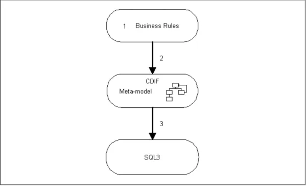
1.1 Aim
The aim of this work is to propose an extension to the Case Data Interchange Format standard, so that it can express and support the transfer of business rule models. In addi-tion, we define a mapping procedure which maps business rules from the conceptual mod-eling level via the repository standard CDIF (using the proposed extensions) to SQL3. Figure 1 introduces this idea graphically. The mapping procedure only treats a specific type of business rule.
1.2 Objectives
1.2.1 Choosing a BR model
The first objective is to define the requirements for a model for expressing business rules. We search the literature for suitable models that fulfill these requirements. A choice of one specific modeling technique is made for representing business rules. The motivation for the choice of that specific model is further elaborated on. Every atomic semantic construct and constraint of that model is listed. We also show why the current standardized mode-ling techniques in CDIF are insufficient for expressing business rules.
1.2.2 Extending CDIF
The second objective is to propose an extension to the CDIF integrated Meta-model that can incorporate the semantic constructs of the chosen rule model. The extensions have to follow the rules stated in the standardized subject area of extensibility. The design process is carried out by systematically creating a corresponding semantic construct in the CDIF integrated Meta-model (by adding a Meta-entity, Meta-attribute or Meta-relationship), for every atomic semantic construct in the chosen model. This work claims systematicity, not completeness in the mapping procedure. This means that we cannot necessarily account for all combinations of atomic constructs. It is the opinion of this author that this restric-tion does not severely limit the usage of the mapping procedure (presented in the last part of the second objective below), since most models used in every day practice do not pos-sess these characteristics. All design decisions should result in extended semantic con-structs in CDIF that allow for a one-to-one (1:1) mapping of a business rule model to CDIF. This requirement results in the ability to use the mapping procedure backwards. The last part of the second objective is to define a mapping procedure that uses the extended Meta-model. This work is strictly analytical, i.e. it does not propose and imple-ment a database system. The alternative would be to impleimple-ment the CDIF integrated Meta-model in a relational database system. However, this approach would not yield any addi-tional information. The cardinality and participation constraints on the integrated Meta-model can be tested without performing a mapping to a relational Meta-model. The CDIF Inte-grated Meta-model can also be used to design a repository. This is not the purpose of this
work and it should not be confused by the fact that the integrated Meta-model is extended (the Meta-model produces the transfer). This implies that any comments regarding how well suited the CDIF integrated Meta-model is to provide the basis for a repository is not considered to be of interest, i.e. we will stay with the original goal of CDIF as a transfer format by focusing on issues relating to the preservation of semantics from the chosen model aiming for minimal extensibility.
1.2.3 Mapping to SQL3
The third objective is to specify a procedure for mapping the CDIF representations, i.e. the extended Meta-model expressing the business rules, into triggers in the forthcoming SQL3 standard. The mapping procedure only regards triggers without calls to stored procedures. The reverse mapping between the triggers via the CDIF representation to the conceptual business rule model is guaranteed by the fact that the design of the Meta-model only takes into account constructs that allow for a one to one (1:1) mapping.
1.3 A scenario
How does all this fit together? Why the interest in an interchange standard? How is CDIF going to be used in practice? What are the benefits of using the standard? Why can we not use vendor specific bridges between all tools for our business rule models?
Let us consider a scenario that explores these issues. Assume that we have a multiple CASE tool environment. The tools involved have the ability to create and edit business rule models. In order to exchange rule models developers would have to recreate models in a target tool. This is a very costly and time-consuming activity. It is very likely that it would introduce errors and also require experts of the source tool as well as the target tool. One solution would be for all tool vendors to specify export/import interfaces to all other tools. This would result in a large number of interfaces (even if feasible) and it is likely that the vendors would support only the major competitors, or worse, they would only allow importers! In addition the vendors would need to track every change in the other vendors’ Meta-models in order to guarantee successful transfers at all times. The scenario where a vendor can exchange information only with a few other major vendor tools can
choose a CASE tool based on their specific requirements [Bub88]. This issue is addressed by the ISO standard for evaluation and selection of CASE tools [ISO97].
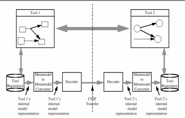
The alternative scenario is that tool vendors adhere to CDIF. The business rule Meta-mod-els would be different in the various tools/repositories (compare with different variants of data models, i.e. different Meta-models). Then, in order to transfer business rule models between these tools the vendors would have to adhere to the CDIF integrated Meta-model that expresses business rule models. This would imply that the vendors have to specify one export/import interface that conforms to CDIF. This guarantees that the various tools could exchange business rule models in a uniform and consistent way. This scenario is presented in Figure 21 [CDIF97b]. The benefits of this scenario are that the developers could choose tools with different capabilities, change tools and versions and always be sure of an information consistency between all tools used. If CASE tool vendors adhere to CDIF this guarantees that it is possible to exchange information between tools.
Figure 2: Transferring business rule models
1. The picture is adapted from a presentation by Johannes Ernst who is a technical officer at CDIF. It has been modified to reflect rule models.
What is the trend in CASE tool usage? Is the exchange of models between various tools a major problem? Steven Kelly, one of the developers of Meta-edit [MET97], considers the question of the trend in CASE tool usage:
“The basic answer is that CASE is growing and will continue to grow [Kel97]”
He supports this statement, for instance, with the findings of Kusters and Wijers [Kus93] that 89% of ISD managers see the future importance of CASE in their organization increasing. Since the CASE tool market is still growing this implies that the exchange problem must be addressed. In addition, Stobart et al. [Sto93] summarize their world-wide findings of problems related to CASE tool usage. One of their main findings is directly related to this work:
“The integration between tools for different software development phases is poor.”
It is the opinion of this author that the CDIF standard addresses this problem in an interest-ing way and this has been a drivinterest-ing factor for this work. Readers interested in CDIF can use this work as a compact introduction to the standard (section 2.4) together with exam-ples (section 4.1 and 4.2.2).
2 Background and foundation
2.1 Introduction
This chapter contains an extensive overview of issues relating to this work. It provides a basis for the project and ties the issues together, forming a background and foundation for a business rule extension of CDIF and a description of mapping business rules from the conceptual modeling level to triggers within SQL3. Section 2.1 defines a business rule with respect to this work and presents a classification scheme for different rule types. Fur-thermore, it provides a number of examples of business rules for every type found in the classification scheme. Section 2.2 elaborates on the need for and achievements of an explicit business rule focus in software engineering. It also identifies major problems on the journey to a rule-based paradigm in software engineering and emphasizes that CASE tool support is crucial. This section also emphasizes the need for a consistent treatment of business rules throughout the software engineering lifecycle and the need for conceptual models of business rules. Section 2.3 introduces CASE tools and repository architectures. This is essential since there is confusion about the definition and role of these products. The aim of section 2.3 is also to clearly state the view of these products taken in this work. Section 2.4 presents the Case Data Interchange Format standard (CDIF). The presentation includes the historical development of the standard, the ultimate goals and the architecture of the standard. Finally, section 2.5 elaborates on active functionality in the forthcoming database language SQL3, i.e. triggers. It presents the arguments for a centralized imple-mentation of rules and elaborates on the structure used to represent rules. It also includes some comments on assertions, including an argument of why they where not considered in this work.
2.2 What is a business rule?
2.2.1 Definition
The term business rule is used in a broad sense in this work, but it has been used differ-ently throughout the literature, often being restricted to semantic integrity constraints [App88]. The definition of a business rule with respect to this work is:
Definition 1: Business rules are statements how the business is done, i.e. guidelines and restrictions with respect to state and process in an organization [Ass88].
2.2.2 Classification of business rules
Probably the most extensive classification made of business rules is that of Ronald G. Ross [Ros94]. This work is built on his view of business rules and this section presents his clas-sification scheme. Barbara Von Halle [Hal96a] has noted that Ross’s view of business rules coincides with the Zachman framework for information system architecture [Zac92], in that a business rule means the natural-language expression used in the business perspec-tive [Zac92, P600 (row 2)]. A rule means an implementable and technology independent piece of logic [ZAC92, P600 (row 3)] and they can be further transformed into technol-ogy-dependent specifications [Zac92, P600 (row 4)]. The terms business rules and rules will be used synonymously in this work, and the context will determine the type of rule discussed.
Ross’s scheme is based on a few basic rule types that can be combined into complex busi-ness rules. There are nine basic types of atomic busibusi-ness rules presented below. In addition there are a number of subtypes and operators on every basic rule type. However, it is not my intention to elaborate on every subtype and operator of every atomic rule type, since this material is too extensive. Those readers further interested in business rules are highly recommended to study Ross’s book which also provides over 500 example rules. These examples also include a diagrammatic representation in the Ross Methodology, which is an extended ER model with additional constructs for expressing rules. The first rule of
instance verifiers below refers to the attribute type “date” of the entity type “order” and
the first rule of type verifiers refers to an IS_A relationship between “customer” and its subtypes “government”, “corporate” and “individual”. All the examples in the nine
cate-gories are collected from Ross’s book and they all have a graphical representation in the book.
1. Instance Verifiers
This type states the possession of instances, i.e. an instance of a constrained object may exist only if the indicated test for possession is satisfied.
Example rules
“Every order must have a date placed at all times” “An order may be placed at most by only one customer”
“To hold a credit account a customer must be “good””
2. Type Verifiers
This type states the existence of a given type, i.e. the rule evaluates the exist-ence of a given type. This is distinguished from the instance verifiers which always count actual instances of a constrained object.
Example rules
“A customer may be either a government, corporate or individual, but never more than one of these types.”
“An active project must have a budget, and vice versa”
3. Sequence verifiers
This type states the changes of instances of constrained objects and usually involves a series of updates. This type of business rule always elaborates on a logical sequence, referred to as an explicit logical sequence.
Example rules
“An order must be indicated as received before any other statuses can accumu-late”
“If the most recent status upgrade for a contracted project is not step-wise, then...”
4. Position selectors
This type states an innate sequence (an implicit sequence) of a database that can be based on a value or the age of an instance. If a business rule refer to an arbitrary sequence then the sequence verifier should be used instead.
Example rules
“If this section of the report is the first section then...” “If this is the fifth section in the report, then...”
“If this is the order with highest total order amount of all, then...”
5. Functional evaluators
This type of rule test values of constraining object(s) as a function of the instances of the object.
Example rules
“All order must be identified uniquely”
“The same effective date never may be used more than once for all orders” “Rental agreement periods must vary by at least 3 days from any other”
6. Comparative evaluators
This type of rule performs a comparison between similar values of objects. Commonly, the values exist of attribute types.
Example rules
“Approved orders require that the total order amount must be less than or equal to the customer’s credit limit”
“If the balance of the account falls below USD 1000, then...” “A customer may be supported only by an agent in the same city”
7. Calculators
This type of rule tests the result of a common computation of values on con-strained objects. Commonly, these values are attribute types.
Example rules
“The amount owed for an order must be the sum of the prices of all products on the order”
“If the amount of a withdrawal is above the average for the account, then...”
8. Update controllers
This type of rule defines constraints on database updates or what result should be produced. This is applied to all instances of a constrained object (except when enumerating the instances), as opposed to instance verifiers that perform
the same operations but with the default “lower limit of one”
Example rules
“Once an account is created, its type never must change”
“An order must not be modified in any way, or deleted, once closed. “If the status of an employee has changed, then...”
9. Timing controllers
This type of rule tests intervals of time on constrained objects. Timers may also be used to switch off and on other rules.
Example rules
“An order must not be deleted for at least one minute after it has been created” “An order must be deleted automatically 30 days after completion”
“An employee must not assist project for more than one year total”
A complementary classification scheme proposed by Barbara von Halle states four types of business rules, which are presented below [Hal96b]. A business rule can fall into one of the four categories:
• Definitions of business rules
• Facts relating terms to each other
• Constraints
• Derivations
Responding to a direct question made by this author of the exact relationship between the two classifications, she states:
“We (Ross and von Halle) both use the term Business Rule (as does the GUIDE business rule project) to refer to Terms (nouns with definitions), Facts (connections among nouns), and Rules (the testing of conditions). My constraints and derivations fit under the heading of Rules. Ross periodic table of ruletypes also fits under the heading of Rules. My classification is at a higher level and he gets down to the atomic pieces based on the kind of “work” or “computation” that a rule performs.”
Definitions of terms in a specific language state a large amount of information concerning how we perceive things. This is the most basic aspect of a business rule and it is often described as entities in Entity-Relationship models. An example of a definition is an invoice, which a person probably associates with a number of characteristics, e.g. “it con-tains information about a customer” and “it concon-tains information concerning delivered goods and prices”. Facts relating terms to each other express business rules that defines the structure of the information in a company. The facts are often described as attributes, rela-tionships or generalization structures in Entity-Relationship models. An example of a fact is that “a customer can hire a car”.
It is common that a company has defined constraints on the possible operations of stored information. This class of business rules are actually the inverse of the facts, since they state what can not be done while the facts state what is possible. The constraints often refer to definitions and facts. Some of the constraints are possible to express in ER models, e.g. integrity constraints and domain constraints while some constraints have to be expressed in other formalisms or extended ER approaches. One example of such con-straints is that “no employee is allowed to have a higher salary than the executive”. Deriva-tions are derived from other facts and specifies new information. One example of a derivation rule is “the weekly charge is the daily rate times seven minus the discount”. Note that these types of rules assume an ordering when we obtain the information, i.e. we must know “the daily rate” before we get to know “the weekly charge”. This ordering has to be defined by the analyst.
2.3 Are business rules important?
All enterprises are guided and controlled by a huge amount of business rules and they are the very foundation of structure and actions. The GUIDE project [Gui96] states:
“It is important to note that an enterprise’s business rule applies, regardless of the form used to express it. Business rules have been in place and companies have been responding to them long before anyone ever dreamed of formalizing them. Business rules are an underlying reality in an organization, independent of an analyst’s attempt to structure and describe them.”
Von Halle [Hal97] also emphasizes the fundamental importance of business rules:
“No matter how you capture it, the logic behind business requirements actually rep-resents a set of business rules.” (p. 16).
Now, assume that a company suddenly would lose all its business rules. It is plausible that the company then would have to struggle to stay in business, i.e. without business rules a company would probably not stay viable for long. What is the nature of these business rules? Some are very “high-level” policies or specifications of routines used in the daily management of the enterprise. It is common that rules are specified in various documents, e.g. working descriptions. It is important to note that the rules incorporate both structural and dynamic aspects of how business is being done. Examples of the origin of rules could be company goals or processes. Some rules may be informal and general, forcing the employees to interpret them and some may be reasonably formal.
Probably, a large subset of all the rules have an information system component. It is these types of rules that will be treated here. These rules typically places constraints on database states, derives new information or executes actions when certain events occur. The usual treatment of business rules throughout the software development process is that they are implicitly expressed in various models and documents, and not explicitly attended to. Just recently there has been an increased interest in the explicit treatment of business rules in systems development [Kno94].
2.3.1 A Business rule focus in Software Engineering
There are many different ways for a systems analyst/designer to describe an enterprise, each way representing a specific view, which helps the developer to model the interpreta-tions of the UoD. There are well established methodologies for this work, e.g. function oriented, data oriented and event oriented methods. With these methods it is possible to describe how information flows, functions are performed and data structured within an enterprise. It is easy to see the need for modeling of different views of the enterprise for specifying requirements and designing Information Systems. All these views are “pieces of the puzzle” which promotes the development of good quality systems.
Loucopoulos and Kopankanas [Kop89] states:
“The knowledge found in an application domain can be varied and with many facets and it is a truism that there does not yet exist an ‘ideal’ representation formalism that possesses logical adequacy, heuristic power and notational convenience that is needed for encoding satisfactorily all types of domain knowledge.” (P. 1).
However, is it possible that a dimension is missing? Several authors believe that there is a missing view and their view is based on the concept of business rules [App84] [Mor93]. There are even authors who call for a “paradigm shift” in favour of a business rule focus in information systems development [Ass88]. A business rule view complements traditional views on information systems, as stated by Barbara von Halle [Hal96c]:
“Business rules bridge the gap between process and data; between behavior and information” (P. 12).
A business rule focus would imply starting off with an analysis of user requirements, goals and business policies and eliciting the business rules from these. First after this procedure, an analysis whether the rules should be stated in data models or as separate business rules in a rule model would be performed. See figure 3 for a presentation of these ideas created
by Barbara Von Halle [Hal96b, p.16], where she proposes a synergy between business rules, data models and object models. In her opinion it is a good idea to start off with an analysis of present business rules, to classify those and finally create data models and rule models. This allow definitions and facts to be expressed in data models, expressed as enti-ties, attributes and relationships, together with some constraints, e.g. cardinality and par-ticipation constraints on relationships between entities.
However, data models lack the ability to express dynamic behaviour, and therefore the remaining constraints and all of the derivations would be expressed in rule models in other formalisms. This is an alternative to the traditional ways of working, e.g. when focusing only on data modeling we could try to find the relevant concepts with respect to the future information system, their characteristics and relationships between concepts, which through refinement eventually would specify the design of a database. This would capture the business rules that are possible to express in traditional data models. However many business rules are not possible to specify in a data model. They would probably be implic-itly expressed in various models or not modelled at all until it is time to convert the rules into code.
Probably a number of the business rules would be implicitly expressed in various process models and thus inconsistently implemented (scattered) into procedural code. This makes it very hard to know what business rules that apply to the system and where they are implemented. It would be very hard to accommodate for quick changes. This work is focused upon the constraints and derivations that are impossible to express within tradi-tional data models. In contrast to these ideas recent advances in the area of active data-bases have put a “rule focus” on the design of datadata-bases, see e.g. the conference on rules in database systems [RIDS97a].
2.3.2 Advantages of an explicit rule focus
Sources in the literature argues that several achievements could be made if an explicit rule focus is adopted in software engineering, i.e. incorporated into methods and modeling techniques. There are proposals that business rules serve as a good base for communica-tion between system designers and business people (users), as stated by Loucopoulos [Lou95]:
“The major efforts in addressing business policy modeling involve the use of a rule-based paradigm which provides a natural mapping from enterprise to information systems concepts.” (p. 100).
These ideas are also consistent with those in [Hal96b] which state that business rules express definitions, facts, constraints and derivations in the same language business people would use to describe them. The idea is that it is easier to communicate with business peo-ple in terms of business rules, rather then in information systems terms, e.g. data, data flows and processes. It has also been showed that the rule paradigm is a good means for expressing business knowledge [Ass88].
In addition to promoting communication, probably the most important achievement of an explicit business rule focus concerns changeability and maintenance. Ross argues that there has been too much attention on speed and elegance in implementation of systems, and he argues that real business challenge is about changeability [Ros94]. And indeed, maintenance is a timeconsuming and expensive problem identified in the literature. A business rule focus in software engineering may very well be the answer to this problem. USOFT argues in a white paper [Uso97b]:
“People usually explain why maintenance is so difficult by explaining the complexity of technology, that’s only right maybe 90% of the time. The right answer is that they never bothered to unify the business rules in the first place. They don’t know what business rule are implemented, so they don’t know how to find and change them.”
If business rules are neglected and only stored implicitly in various models, they are prac-tically impossible to find and altered in the application code. However, if there is support for business rules throughout the software engineering lifecycle, starting off with concep-tual models of rules, then changes in the organization with an impact on the information system can easily be accounted for. USOFT states (in the same paper):
“When the programmer leaves and the Information Technology group is left to maintain the system, can they do it? Can they find the rule, assess the impact and make the change directly, and know what the implications are? That’s the sign of a quality software product that is truly addressing a business need, as opposed to a
programming need. Business can then concentrate on the business instead of the process of the business.”
An explicit treatment of rules can also be used to fully take advantage of the power of active functionality in databases, as stated by Herbst [Her95]:
“To fully use the potential of these rule-based mechanisms, a rule-based systems analysis methodology seems necessary.”
It has been noted that this active functionality is well suited to implement business rules in a wide variety of applications [Bou97]. Common methodologies for analysis and design of databases are insufficient for the new active mechanisms found in research prototypes and commercial DBMSs [Tan92] and [Sim95]. Since there is little or no support in Software Engineering methodologies and modeling techniques, the designers have to use ad-hoc solutions to incorporate the active functionality late in the design process. The problem with this procedure is that the implementation model easily can bias the semantics from the real world [Tan92], i.e. there is no conceptual modeling of rules.
Business rules usually constitute a main part of an information system and are scattered all over the system, often deep buried in procedural code. There is a need for the benefits of a centralized and non-redundant implementation of business rules. This development calls for a systematic and consistent treatment of rules throughout the software engineering life-cycle. It implies new or revised methodologies for conceptual design of active databases, since the existing methods were developed for passive databases [Tan92]. In the area of active databases the focus has been set on the more technical aspects such as event lan-guages, transaction models and rulebase management. The conceptual modeling of rules has not gained a lot of attention and rules placed in the context of software engineering even less - something which has been discussed recently [RIDS97b]. However, to effec-tively develop active databases requires that these issues are addressed, e.g. as in this work.
2.3.3 Problems
Is it straight forward to adopt an explicit business rule focus in software engineering? The answer to this question is; no. There are a variety of important issues that needs to be
resolved in order to efficiently use the business rule paradigm. The first and most basic issue regards the definition and classification of business rules. There is no consensus within the database community on what a business rule really is. For the rule-paradigm to gain acceptance it is necessary to achieve this consensus.
The second issue regards the lack of support for business rules in software engineering methods and modeling techniques. Analysts and designers need formal guidance to cap-ture the rules (methods) and express them in various modeling techniques (models). These models need to be refined throughout the SDLC. An example of a business rule analysis scenario is provided by von Halle [Hal96d]. It is founded on the Zachman framework [Zac92], and describes the steps one at a time. Von Halle also discusses the problem of business rule support in different software engineering methods (waterfall-based, proto-typing-based and OO-based methods) [Hal97].
This work only consider models with the ability to express business rules and hence the problem of method support is outside the scope of this dissertation. It has been argued in the literature that there is a need for conceptual models of business rules [Kop89], [Lou90], [Kno93] and [Ros94]. Conceptual models offer a number of advantages and are frequently used in software engineering. They are a special type of models which gener-ally are characterized by their high-level nature, which means that they are closer to how users perceive the world. Furthermore, a conceptual model is free from implementation details, thus the models are fairly easy to understand and serves as a base for communica-tion. This work addresses the need for conceptual models expressing business rules by identifying such approaches in the literature. Furthermore, we compare the candidate models for expressing business rules. The result is the choice of one specific model (in addition based on other criteria than merely being conceptual - see section 3.1) which serves as the base for an extension of CDIF to incorporate business rules. The last issue regards the mindset of those interested in business rules. The developers need to recognize that business rules are important for a specific project, e.g. the company wants to trace the rules to implementation and deployment or it should be possible to make quick changes among the rules. We think that these problem will be addressed when enterprises acknowl-edge that business rules are an important asset. This may take a while, but bear in mind the
2.3.4 Rules in information systems
Only a subset of all rules that control the business are relevant with respect to the informa-tion system. As meninforma-tioned above, they can be recognized by the fact that they have at least one or more rule components that reside within the information system. See figure 4 for a description of possible locations of rules. The rule-set marked with nr. 1 represents rules that are not interesting to model with respect to the information system. Examples of such rules can be human behaviour rules and norms which indeed are very important for com-panies, but have no direct connection to the information system. The rule-set marked with nr. 2 represents rules that are not possible to formalize. Examples of such rules can be gen-eral policies and guidelines. The rule-set marked with nr. 3 represents rules that should not be modelled due to their inherent flexible nature. The rule-set marked with nr. 4 represents
Figure 4: Rules in information systems
rules that reside within the application code. Examples of such rules can be that a cus-tomer should only be allowed to place orders if he/she has got the sufficient credit rating. The rule-set marked with nr. 4 represents rules that reside within the database. This means that the database system enforces the rules. Examples of such rules can be that no employee is allowed to have a higher salary than the executive. Note that the examples of rule-sets 4 and 5 can be interchanged, i.e. it is up to the analyst where he/she wants to specify the rules. A discussion of pros and cons of placing rules in the database compared
to the application programs will be one of the issues in the chapter dealing with the data-base language SQL3.
2.3.5 Business rules and CASE support
As mentioned above We believe that the explicit modeling of business rules can become a major building block in software engineering and gain acceptance if rule models can be handled with CASE support. So, what are the specific arguments for the need of tool sup-port for business rule models? Herbst et al. argues that rule models of realistic size quickly become extensive and complex [Her94]. Recall that we argued that an enterprise is guided by a huge amount of business rules which need to be attended to in the development of information systems. Also, for a rule paradigm to be effective the process of designing business rules must be incorporated into the traditional information systems development and database design process.
Figure 5 presents these ideas graphically. The original ideas of the figure is presented by Elmasri/Navathe [Elm94] and in addition this author have added the business rule dimen-sion. In this figure the database design process incorporates various models in a three lay-ered approach. Commonly the conceptual model is an ER variant, the logical model is based on an abstract relational model and the physical model is the database scheme expressed in DDL statements according to a vendor specific database system.
A common feature is that the tool can produce DDL statements for a variety of vendor specific databases. In addition it is possible to perform bi-directional mappings of the var-ious models. This is useful to quickly accommodate for changes from the conceptual level (the data model) to the physical model (the DDL statements) or vice versa. A typical map-ping from a conceptual data model to an abstract relational model would include deriving tables from entities, columns from attributes etc.
Figure 5: The BR design process
The mapping procedure could be automatic or semi-automatic, e.g. there are a variety of mapping alternatives when considering an IS_A relationship [Elm94]. This distinct lay-ered approach of database design is now gaining acceptance in modern CASE-tools, e.g. S-Designor from Powersoft [POW97]. The process of designing business rules would be similar to the database design process, and carried out as a parallel activity. This would imply creating conceptual business rule models, logical business rule models and finally vendor specific DDL statements, e.g. triggers. In this scenario of the design process, busi-ness rules can play a crucial role in the development of information systems. The tool would provide automatic or semiautomatic mapping of rule models from the conceptual
modeling level to executable code statements. Changes could easily be accounted for by automatic support for their implications, e.g. if we change the conceptual rule model we could quickly derive the new modified DDL statements and vice versa. In this scenario rule models would complement traditional models supporting the database design process. The tool could also provide associations between models, e.g. it is common that rules affect data model objects. An example of this is the business rule “orders are only accepted if the customer has a sufficient credit rating. Obviously, this business rule involves the attribute “credit rating” of the conceptual data model entity “customer”.
2.4 CASE tools and repositories
2.4.1 Introduction and definitions
In order to explain the role and meaning of a CASE-tool/repository with respect to soft-ware development, it is a good idea to start of with a discussion of CASE tools, since they are one of the main reasons for the increased interest in repositories:
Definition 2: A CASE tool is an application that supports the developer of software throughout the different stages of the software engineering lifecycle [Lou95].
The aim of CASE tool usage is to increase the productivity and quality in software engi-neering. It also assists the developer in organizing huge amounts of information about the application development. Commonly, a CASE tool supports one or more methodologies, which traditionally have been the structured approaches, e.g. DeMarco [Dem79]. In recent years other methodologies are also supported, e.g. Object Oriented methods. When a method is supported this means that the CASE tool enforces method-specific rules. There are also CASE shells with which a user can define his own method and enforce its specific method rules, e.g. metaedit [Met97a]. There are now a wide variety of different tools with different focus. However, common for most of them is the possibility to create models, edit text and generate code. There are different types of classifications of CASE tools in the literature. One classification is based on the distinction between an early and a late stage of systems development. This is referred to as upperCASE and lowerCASE respec-tively. UpperCASE supports the analysis of domains resulting in a requirements specifica-tion and uses techniques like dataflow diagrams and structure charts. LowerCASE
supports the design of the information system and generation of code. It usually starts off with the conceptual model of the system which has a formal foundation as opposed to the formalisms used in requirements modeling [Lou95]. LowerCASE tools typically support the automatic generation of SQL statements from conceptual models. There is also the notion of integrated CASE tools (ICASE) [Lou95] which supports the entire development process. The development of ICASE was one of the reasons behind the increased interest in repositories. There was a need for a central storage facility, which would provide shar-ing of engineered objects (models, code, documentation etc.) between the earlier and later phases in the software engineering process. However, maybe even more important was the “CASE tool explosion” which denotes the quick growth in the number of available tools on the market. Since tools usually are specialized in different tasks, organizations often have a multiple CASE tool environment making it difficult to share objects between tools. The reason for having a multiple CASE tool environment is that no tools provide support for all the stages in the SDLC. Even if they did, different tools would be specialized in dif-ferent tasks. Organizations began to realize that a lot of time was spent translating models from different tools and that it was difficult to reuse models. Also, since many CASE tools did not permit the existence of multiple model versions a vendor independent repository would provide support for this feature [Tan95]. A repository was the solution to this prob-lem since it provides a central storage facility which can be shared among many different CASE tools.
Definition 3: A repository is a shared database of information about engineered artifacts [Ber94].
The term repository is used rather inconsistently among both users and vendors, so to complement the definition above consider the following description [Ber94]:
“...it’s implementing a layer of control services on top of the DBMS, called a repos-itory manager, and integrating it with many tools. The result of this integration is a framework for metadata management, called a repository system.” (p. 1).
A repository can be viewed as a stand alone product, however it is common for CASE tools to include a repository in their architecture. Hence, the CASE tool is built on a repos-itory which store the different engineered objects. These objects can be used by the
differ-ent activities in the tool, e.g. creating a conceptual data model or a logical data model. The repository must have an import/export facility which specifies the external representation of the internal meta-data in the repository. This allow the tool/repository to be able to import/export the engineered objects to other tools/repositories.
2.4.2 CASE tool/repository architecture
There is no specification on exactly what a repository architecture should consist of, how-ever a least common denominator usually exists of [Tan95]:
• The Repository Metamodel: It represents the description about all the infor-mation stored in the repository. It is the Meta-model that express what kind of information the repository can store. The Meta-model should be extensible, i.e. it should be possible to extend the Meta-model to be able to store new types of engineered objects.
• An underlying DBMS: The contents of the repository is defined in the various Meta-models and implemented in a database. The rationale for using a data-base is the organization of huge amounts of information and DBMS function-ality, e.g. the possibility to perform queries. The database can be relational or Object-oriented.
• Repository-Supplied Utilities: The repository functionality that extends that of the underlying DBMS. An example is versioning.
• Repository security: The security depends on the degree of separation from the repository and the database. An example is repository policies.
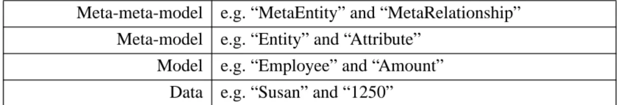
Basically, what distinguishes a repository from a database is the integrated Meta-model. It is the Meta-model that defines what information that can be stored in the repository. Since a repository need to be extensible, there is a need of four levels of abstraction of the Meta-models (see table 1 on page 35) adapted from [Tan95]. The bottom level is the operational level which defines the instance data, e.g. a specific customer “Mr. Green” and constitutes the production database. The next level is the data about the data, e.g. the entity type CUS-TOMER that defines the characteristics of a CUSCUS-TOMER. For example, it can include information of the attributes of CUSTOMER, datatypes and recent updates. The third
level is referred to as the Meta-model and describes the elements of a particular design notation together with the rules of that model, i.e. the Meta-model defines the modeling language. It is called Meta-model since it is in fact a model about a model. This level rep-resents the “tool’s perspective”. Finally, the fourth level of abstraction is the Meta-Meta-model which defines the Meta-Meta-model of the MetaMeta-Meta-models components, e.g. objects and relationships. This level represents the “repository’s perspective” and it specifies a tool independent Meta-model.
2.4.3 Repository functionality
The basic functionality of a repository is defined by the underlying DBMS and include tra-ditional database functionality, e.g. a data model, views, integrity control and queries. In addition, a variety of functions are specific to the repository itself. Examples of such func-tionality is stated in [Ber94] and includes the ability to check-out/check-in of objects. This means that a persistent lock is performed on the object in use. Other functions are version control, which aims at managing the different versions of an object throughout it’s lifecy-cle. Since everything in a repository can relate to everything a notification mechanism is needed which handle change control. These examples only represents a subset of needed functionality of a repository. The best way of implementing this functionality is to make the control userdefined, which makes it more flexible.
2.4.4 The Meta-model
The Meta-model is the basic building block for data integration and this work elaborates extensively on the Integrated Meta-model of the repository standard CDIF. So, what are the characteristics of a Meta-model and why has there been an increase in interest, for Meta-models in recent years? A Meta-model can be used for a variety of tasks, e.g. a con-ceptual scheme for repositories, a definition of a modeling language or a transfer format that aims at integrating tools. It usually consists of a small subset of constructs expressed in some modeling technique with the possibility to model meta-classes/entities, meta-rela-tionships/associations and meta-attributes. These constructs makes it possible to formally define a modeling language of some sort. There are some important requirements on a Meta-model. First of all, it has to cover everything in the modeling language. This may seem obvious but even simple modeling languages include many constructs and
combina-tion of constructs, e.g. consider relacombina-tionships in an ER model; n-ary relacombina-tionships, con-straints on relationships, relationships on relationships etc. Second, the quality of the model must be good, meaning that it should be capable of storing your model without loss of semantics. Third, the Meta-model need to be extensible since there will be situations when it is insufficient. Consider, for instance, special requirements in real life projects, e.g. including timing information into a dataflowdiagram. Also, the extensibility must be straightforward. This can be tested by adding your semantic constructs into the Meta-model and see if it fits naturally and does not disturb other elements. Finally, integration of Meta-models are important since the better it is integrated with other Meta-models from other areas, the more stable and “futuresafe” it will be. So, why have Meta-models become so interesting lately? Some ideas around this issue are expressed in [Met97b]:
“Metamodeling has been around for at least 10 years, but with the advent of the Internet and particularly the Intranet, data integration is something that is seriously getting attacked now”
Also, as elaborated on in the section on repositories, a lot of the new technologies like CASE shells (based on an extensible Meta-model), repositories and dataexchange between tools are all based on a Meta-model.
2.4.5 CASE tool/repository standards
The CASE tool market exploded in the number of available tools in the late eighties. Today, there are hundreds of different CASE tool products from a great number of ven-dors. These tools have greatly increased productivity, quality and reusability [Ban91] in software engineering. Many companies possess a multiple CASE tool environment and this has led to severe problems in the exchange of information between tools. As the need for exchange of data between CASE-tools have grown, this has put a pressure on the development of standards for repositories. In order to share data between tools there has to be an agreement on the Meta-models that represents the data. Otherwise every tool vendor would have to create export and import facilities for all the other vendors CASE tools. If the vendor community can agree on a specific repository standard or a standardized exchange format between tools/repositories, every tool vendor only need to specify one
import and export facility to share models with other CASE tools. This would obviously ease the integration of CASE tools and cut costs. The most common standards today are:
• CDIF (Case Data Interchange Format - EIA)
• IRDS (Information Resource Dictionary System - ISO)
These two standards are different; CDIF specifies the export/import of a CASE tool/repos-itory and IRDS specifies the requirements for a repostool/repos-itory. This project elaborates only on the repository standard CDIF. This has been a prerequisite and the motivation for the choice of this particular standard is as follows. Recently, there has been an increase of interest in CDIF and it is currently being merged into ISO’s standardization work. CDIF is a family of standards and provide support for the most common used methods in the soft-ware engineering process. The integrated Meta-model of CDIF is extensible, making the standard very flexible. Furthermore, it is vendor and method independent. CDIF is also currently being supported by some important vendors, e.g. Oracle, Powersoft and Unisys. CDIF is also working with the OMG standard group and UML [RAT97]. The repository standard IRDS does not deal with the exchange of data between CASE tools, rather it defines the requirements of a repository. The IRDS2 [IRDS97] standard is currently undergoing work and the original IRDS is seen as out of date [Tan95].
2.5 CDIF
2.5.1 Introduction
Originally, CDIF was a joint venture between major CASE tool vendors and user organi-zations. It was adopted by the Electronic Industries Association (EIA) in October 1987 and recently also by the International Standards Organization. The main idea of CDIF is to define Meta-models according to an entity relationship modeling paradigm. Different modeling techniques, such as data modeling, data flow modeling etc. can be transferred in a uniform way between CASE tools if vendors adhere to the standard. CDIF is not a spec-ification of a CASE tool or a repository; it specifies an export/import interface of a CASE tool/repository. The interface exists of an external representation of a CASE tool’s internal data. Figure 62 presents the internal view of a CASE tool that adheres to CDIF. CDIF is not a single standard, rather it is a family of standards. The CDIF family of standards
include an integrated Meta-model and a transfer format definition. It can be divided into three groups where the first group defines the architecture, the second group defines a transfer format and the last group defines the integrated Meta-model (see below). The inte-grated Meta-model defines what type of modeling techniques that can be used. Further-more, the integrated Meta-model is divided into subject areas (SA). These subject areas define data definitions, common constructs in various models and a variety of modeling techniques. Every subject area is defined in a separate document. This permits the CDIF standard to evolve over time to include more modeling techniques. It is important to note that the subject areas represents views of the Meta-model, not partitions. This means that a concept is only defined once in the Meta-model, even if it is used in several subject areas.
Figure 6: The internal view of the tool
2. Picture 6 and 7 are adapted from a presentation by Johannes Ernst who is a technical officer at CDIF [CDIF97b].
2.5.2 Subject areas
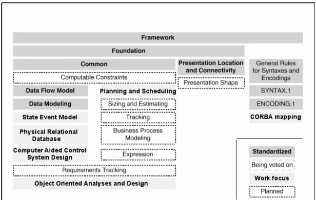
This section presents the subject areas within CDIF. Note that figure 7 specifies the work of CDIF, e.g. “work focus” in the figure does not specify the focus of this work.
Figure 7: The CDIF subject areas
The CDIF architecture is given below together with references to specific subject areas in the standard (* denotes that the subject area is not a released standard yet). References to the standard documents is only provided if it is used in this dissertation:
Defining the CDIF architecture:
"CDIF CASE Data Interchange Format - Overview" [EIA106] "CDIF / Framework for Modeling and Extensibility" [EIA107]
Defining the transfer format:
"CDIF Transfer Format / General Rules for Syntaxes and Encodings" [EIA108] "CDIF Transfer Format / Transfer Format Syntax SYNTAX.1" [EIA109] "CDIF Transfer Format / Transfer Format Encoding ENCODING.1" [EIA110]
"CDIF Transfer Format / OMG/IDL Bindings MIDDLEWARE.1" *
Defining the CDIF Integrated Meta-model:
"CDIF - Integrated Meta-model / Foundation Subject Area" [EIA111] "CDIF - Integrated Meta-model / Common Subject Area" [EIA112] "CDIF - Integrated Meta-model / Data Modeling Subject Area" [EIA114] "CDIF - Integrated Meta-model / Data Flow Model Subject Area"
"CDIF - Integrated Meta-model / Data Definition Subject Area" * "CDIF - Integrated Meta-model / State Event Model Subject Area" *
"CDIF - Integrated Meta-model / Physical Relational Database Subject Area" *
"CDIF - Integrated Meta-model / Presentation Location and Connectivity Subject Area" "CDIF - Integrated Meta-model / Object-Oriented Analysis and Design Subject Area" * "CDIF - Integrated Meta-model / Comp. Aided Control System Design Subject Area" * "CDIF - Integrated Meta-model / Project Management Planning Subject Area" *
"CDIF - Integrated Meta-model / Business Process Modeling Subject Area" * "CDIF - Integrated Meta-model / Expression Subject Area" *
2.5.3 Detailed description of the subject areas
This section contains information about some of the fundamental subject areas. It is not my intention to cover all of them, since most of them represent different modeling tech-niques. CDIF defines “data content” without specifying a syntax or API which would severely restrict the benefits of a standard. The different subject areas can be divided in two categories; the semantic information and the diagrammatic representation of models. A semantic concept can have zero or more graphical representations, or there could be models which are only in graphics. Furthermore, CDIF distinguishes what information to be transferred from the definition of how to transfer it. The information content of the Meta-model defines what information to transfer and the transfer format defines how the information must be structured, in order to complete a successful transfer. The Foundation
Common SA is used to define concepts that are shared between many modeling tech-niques and the Data definition SA contains the information needed to define data. This subject area is referenced by the other subject areas when defining the data content of any metaobject.
Figure 8 presents a partition of the CDIF Integrated Meta-model, i.e. the Foundation SA (RootObject, RootEntity and RootEntity.isRelatedTo.RootEntity) and the Common SA (All the other meta-entities and meta-relationships in the figure). The Meta-model is expressed in the same EER variant as used in CDIF to specify the integrated Meta-model. An example describes how it is read: “A RootEntity may use an alternate name and it can use at most one (and only one) alternate name”. It is interesting to note that this way of specifying the cardinality constraints is the opposite to most ER variants, e.g. the Elmasri/ Navathe variant [Elm94].
The three Meta-entities RootObject, RootEntity, and the Meta-relationship
RootEn-tity.IsRelatedTo.RootEntity are abstract objects and provide the basis for the inheritance
hierarchy of the integrated Meta-model. RootObject is the root object to the CDIF Attrib-utable Meta Object Hierarchy (the IS_A hierarchy in the model). It holds the Meta-attributes CDIFIdentifier, DATECreated, DATEUpdated, TIMECreated and
TIMEUp-dated. Since it is the root object, every Meta-entity and Meta-relationship inherit these
Meta-attributes. New Meta-attributes can be added using extensibility, however it is not possible to specify a supertype of this object. Of the Meta-attributes stated above, only the
CDIFIdentifier is mandatory and need to be unique whenever it is used.
The relationship between the data modeling subject area and the common and foundation subject areas is that all Meta-entities found in the data modeling SA are subtypes of Semantic InformationObject. Hence, all meta-entities inherits the meta-attributes of RootObject, RootEntity and SemanticInformationObject. The same applies to other mode-ling techniques expressed in other subject areas.
A small example of how the Meta-model for the data modeling SA is used is presented in section 4.1.1 (p. 60).
Figure 8: The foundation and common SA
The two most important subtypes of RootEntity is SemanticInformationObject and
Pres-entationInformationObject. The SemanticInformationObject describes objects in a
mode-ling technique, e.g. objects in a data model or business model. Examples of objects in a data model are entity, attribute and key. So for instance, the objects in the Meta-model of the data modeling SA are all subtypes of SemanticInformationObject and therefore, also inherits its Meta-attributes. These Meta-attributes are BriefDescription and
FullDescrip-tion. The PresentationInformationObject describes graphical information about models,
e.g. cordinates and shape of objects. It is also described in a separate SA. CDIF is a vast standard with many standard documents and in order to obtain more detailed information about the architecture we refer to the CDIF website [CDIF97a]. There is also support for defining types and domains within the data definition subject area. CDIF does not aim at covering every modeling technique in the software development process. Instead it is pos-sible to extend the Meta-model with the aid of the subject area framework for modeling