Research
Report number: 2019:04 ISSN: 2000-0456 Available at www.stralsakerhetsmyndigheten.se
Dosimetry in environments
surrounding a laser-plasma
accelerator
2019:04
Authors: Olle Lundh
Ylva Ranebo
Kristoffer Svendsen Lunds universitet, Lund
SSM 2019:04
SSM perspective
Background
Modern laser technology makes it possible to generate ultrashort pulses
with a very high peak power. At the Lund Laser Centre, a high-power
laser facility in Lund, Sweden, laser pulses having a duration of
approxi-mately 30 femtoseconds are generated with a maximum peak power of
up to 40 terawatts. When these pulses are focused, extreme light
inten-sity is achieved. For example, when atoms in a gas are hit by these pulses,
they are ionised almost instantaneously, resulting in the main part of
the laser pulse interacting with a plasma consisting of free, negatively
charged electrons and positively charged ions. The electrons are quickly
displaced by the laser pulse whereas the heavier ions largely remain in
place, resulting in a very strong electrical field.
The research conducted in the field is spurred by the potential to create
applications where charged particles are accelerated to relativistic
ener-gies over very short distances in the strong electrical fields. This
tech-nology may allow for the development of new and much smaller types of
accelerators for applications where for instance linear accelerators are
used today.
Ionising radiation occurs around these laser plasma accelerators in
con-nection with a range of different processes, both when the laser pulse
interacts with the plasma, and when the accelerated particle beam is
slowed down. It is well documented in the literature that ionising
radia-tion is generated when this technology is used; however, the Swedish
Radiation Safety Authority (SSM) has, from the perspective of radiation
protection, identified the need for both an overall analysis and in-depth
knowledge relating to the radiation environment around laser plasma
accelerators.
Outcomes
This report demonstrates that the ionising radiation generated around
laser plasma accelerators has a strong correlation to the peak power of
the laser pulses. Nonetheless, the experimental arrangements can show
great variation, for which reason general conclusions cannot be drawn.
RelevanceThis report gives insight into the radiation environment around laser
plasma accelerators from the perspective of radiation protection, and
may be used as a tool for supporting SSM’s licensing reviews and
regula-tory supervision in this field.
Need for further research
Depending on technological progress and its possible impact on the
radiation environment around the equipment in question, a follow-up
study may eventually be required, not only as a basis for updating SSM’s
framework of rules, but also to underpin licensing reviews and
supervi-sory work in the field.
SSM 2019:04
Project information
Contact person at SSM: Pia Eriksson
Reference: SSM2017-2478/7030171-00
2019:04
Authors:
Date: January 2018
Report number: 2019:04 ISSN: 2000-0456 Available at www.stralsakerhetsmyndigheten.se
Olle Lundh Ylva Ranebo
Kristoffer Svendsen Lunds universitet, Lund
Dosimetry in environments
surrounding a laser-plasma
accelerator
i
Dosimetry in environments
surrounding a laser-plasma
accelerator
Ylva Ranebo, Kristoffer Svendsen, Olle Lundh
Department of Physics, Lund University
ii
Summary
Relativistic particle beams are unique tools for the exploration of the frontiers of physics: whether they are used in a particle collider to explore the subatomic world, or to generate X-rays that allow the structure and dynamics of atoms and molecules to be studied. The most powerful particle accelerators can be several kilometers in length and are thus very expensive to build and operate. A new promising method of particle acceleration based on high-power lasers has emerged, allowing significant reductions in both size and cost. When a high-power laser pulse is focused into a gas or a solid target, a plasma is created in which femtosecond or picosecond pulses of charged particles can be accelerated to hundreds of mega-electron-volts, or even more, in an acceleration distance of only a few millimeters.
This report considers laser-plasma acceleration from a radiation protection point of view. An overview is presented of the current status of research on ionizing radiation and radiation doses in the field of laser-plasma acceleration. The generation of ionizing radiation at laser-plasma accelerators is well-documented in the literature, as is the necessity of shielding to ensure personnel safety and to comply with regulations on radiation safety. Laser-plasma-accelerated beams have two specific features: i) the radiation is zero between the extremely short-duration pulses, and ii) the radiation hazards can be well isolated due to the very short acceleration length. However, the secondary radiation field will not differ greatly from that generated when a beam produced with conventional acceleration techniques interacts with matter. It is shown that the magnitude of radiation fields is strongly dependent on the power of the laser pulse and varies considerably between different laboratories. The experimental conditions and goals at each laboratory can also vary greatly, resulting in considerable variations in the number of particles accelerated, which makes general predictions difficult.
Various modeling and simulation methods for estimating radiation fields at laser-plasma accelerators are reviewed. The radiation fields generated during electron- and proton-acceleration experiments at the Lund multi-terawatt Laser Centre were investigated using the FLUKA transport code, in order to demonstrate the usefulness of Monte Carlo simulations. Regarding dosimetry and instrument response, it is also shown that many techniques used for monitoring continuous radiation can be applied to other accelerator fields operating in ultra-short pulsed mode, as long as certain precautions are taken.
iii
Sammanfattning
Partiklar som accelereras till höga hastigheter är ett unikt redskap i en rad olika vetenskapliga områden. Till exempel inom materialforskning för utveckling av nya läkemedel eller bränsleceller till stora projekt inom högenergifysik som bl.a. bedrivs i CERN. Synkrotronljus som avges från accelererade elektroner kan användas för att undersöka ett materials egenskaper på atom- och molekylnivå eller för att studera kemiska reaktioner under mycket korta tidsförlopp. Avancerade experiment när partiklar accelereras och kolliderar görs för att undersöka naturens allra minsta beståndsdelar och universums historia. Men de kraftfullaste partikelacceleratorerna kan sträcka sig flera kilometer och är mycket kostsamma. I ljuset av detta har en ny teknik utvecklats, laserplasmaacceleration, baserad på högeffektlasrar som kan korta accelerationssträckan med flera tiopotenser. Genom att rikta en laserpuls på en gas eller ett fast mål, bildas ett plasma där laddade partiklar i femto- till pikosekunder långa pulser accelereras till hundratals megaelektronvolt eller mer, på bara några millimeters accelerationslängd.
Föreliggande rapport redovisar en studie på laserplasmaacceleration utifrån ett strålskyddsperspektiv med syfte att fördjupa kunskapen inom detta område. En översikt ges över det nuvarande forskningsläget om joniserande strålning och stråldoser i olika typer av laserplasmaanläggningar. Att joniserande strålning genereras då tekniken används är väl dokumenterat i litteraturen och att strålskärmning behövs för personalens säkerhet samt för att följa grundläggande säkerhetsnormer. Två specifika egenskaper för laserplasmaaccelererade strålar är att i) i stort sett ingen strålning existerar mellan de extremt korta pulserna, och ii) strålningsfaran kan bli väl isolerad på grund av den väldigt korta accelerationssträckan som tekniken använder sig av. Däremot kommer strålningen som skapas inte att vara annorlunda från vad som uppkommer då en liknande stråle som genererats vid en konventionell accelerator växelverkar med omgivande material. Rapporten visar att strålningen som genereras är starkt beroende på vilken pulseffekt lasersystemet kan leverera. Dock kan de experimentella uppställningarna vid varje laboratorium variera stort och därmed medges inte allmängiltiga slutsatser.
En genomgång ges av olika modellerings- och simuleringsmetoder lämpade för uppskattning av strålmiljöer vid laserplasmaacceleratorer. Monte Carlo-programmet FLUKA har använts i syfte att demonstrera ett sådant simuleringsverktyg och att karakterisera strålmiljön som alstras vid elektron- respektive protonacceleration vid multi-terawatt lasern vid Lunds Lasercentrum. För att utreda instrumentrespons och dosimetriska mätningar vid laserplasmaacceleratorer, kan kunskap tillämpas från andra fält där acceleratorer också används i ultrakorta, högintensiva pulser, t.ex. synkrotronljusanläggningar och linjäracceleratorer. Tekniker som används för kontinuerliga strålfält kan också användas i pulsade, högintensiva fält så länge beaktande tas vid val av instrument, såsom om primär- eller sekundärstrålning ska mätas.
iv
Abbreviations and notations
CPA chirped pulse amplification EPD electronic personal dosimeter
ICRP International Commission for Radiation Protection ICRU International Commission on Radiation Units and
Measurements LLC Lund Laser Centre LWFA
NCRP
Laser Wakefield Acceleration
National Council on Radiation Protection and Measurements OSL optically stimulated luminescence
PIC particle-in-cell
Ti:sapphire titanium-doped sapphire
TNSA target-normal sheath acceleration TLD thermoluminescence dosimeter
E energy e- electron
kB the Boltzmann constant
n neutron p proton
Thot hot electron temperature
v
Contents
Summary ... ii
Sammanfattning ... iii
Abbreviations and notations ... iv
1 Introduction ... 1
1.1 Background ... 1
1.2 Objectives ... 1
2 Laser-plasma acceleration ... 2
2.1 Generation of electron beams... 2
2.2 Generation of proton and ion beams ... 4
2.3 Radiological protection and sources of ionizing radiation ... 5
2.4 A laser-plasma acceleration laboratory ... 7
Layout of the facility ... 7
Repetition rate and annual shot rate ... 10
A laser-plasma acceleration experiment ... 10
3 Survey of published radiological assessments for high-power laser facilities ... 12
3.1 Gigawatt laser systems ... 13
Laser–solid interactions ... 13
3.2 Terawatt laser systems ... 13
Laser–gas interactions ... 13
Laser–solid interactions ... 15
3.3 Petawatt laser systems ... 18
Laser–gas and laser–solid interactions ... 18
3.4 Further reading ... 21
4 Modelling the radiation environment ... 25
4.1 Monte Carlo codes ... 25
FLUKA ... 25
GEANT4 ... 26
MARS15 ... 26
MCNPX ... 26
PHITS ... 26
4.2 Radiation fields at the LLC ... 26
Laser Wakefield Acceleration ... 28
Target Normal Sheath Acceleration ... 28
FLUKA results - Radiation environment ... 29
Comparison with measured dose ... 30
Induced radioactivity ... 34
Particle-in-cell codes ... 36
5 Dosimetry and detector performance ... 37
5.1 Ionization chambers ... 38
5.2 Solid-state dosimeters ... 39
5.3 Particle counting devices ... 39
5.4 Radiation monitoring at the CLF, Rutherford Appleton Laboratory .... 39
6 Conclusions... 41
1
1 Introduction
1.1 Background
Modern science and technology employ beams from particle accelerators as an essential tool in a wide range of applications. Higher energies and higher particle beam quality are required to answer some of the most fundamental questions regarding the origin of our universe, the nature of dark matter, space and time, and the elementary constituents of matter. However, higher energy usually means a higher cost. Today’s conventional accelerators use electric fields generated by radio waves to accelerate electrons and other charged particles to velocities approaching the speed of light. However, the particle energy attainable is constrained by the electric field strength. Breakdown, arcing and even melting of the metallic accelerating structures, will result at a field above a few tens of megavolts per meter. Thus, it is necessary to build longer, more complex and costlier accelerators in order to achieve higher particle energies.
In research on laser-plasma acceleration, new techniques are being studied to accelerate particles by taking advantage of the strong electromagnetic fields that can be sustained in a plasma. In 1979, Tajima and Dawson from the University of California presented and proved a theory that elementary particles could “surf a plasma wave” and be accelerated to relativistic velocities in a few centimeters (Tajima and Dawson, 1979). The electromagnetic energy from a laser pulse is transformed into the kinetic energy of particles, and the first experiments confirming this were performed during the 1980s (Clayton et al., 1985). Later experiments have shown acceleration in electric fields of tens, even hundreds of gigavolts per meter, leading to more than 1000 times higher particle energies per unit length of acceleration than in conventional accelerators. Plasma accelerators could therefore constitute short, yet very powerful, accelerators.
Laser-plasma acceleration has led to a new branch of radiation protection as laser-matter interactions can generate highly energetic accelerated particles. Electron beams with energies in the range of GeV and proton beams of several tens of MeV both constitute a radiological risk.
1.2 Objectives
This report presents a study on radiation protection aspects in the operation of different kinds of laser-plasma accelerator facilities. The aims of this report are:
- to give an overview of the current status of research on ionizing radiation and radiation doses in the field of laser-plasma acceleration,
- to provide an analysis of the types of radiation and radiation doses that workers can be expected to be exposed to,
- to provide suggestions for appropriate instruments for measuring radiation doses in environments where charged particles are accelerated in very short pulses with high intensity,
- to review the possibilities, difficulties, and applicability of existing simulation programs for these radiation environments, and
-
to give an overview of technology development and the expected increase in use of laser-plasma acceleration.2
2 Laser-plasma acceleration
In order to understand one of the key concepts behind laser-plasma acceleration, we will first consider some basic physics. Power is defined as the amount of energy supplied, or expended, during a period of time. Let us assume that we have a laser pulse with an energy of 1 joule, which is about the energy required to lift an apple one meter. If this laser pulse is compressed to an infinitesimally short period of time, such as 50 femtoseconds (50/1,000,000,000,000,000 of a second), then the power will be: 1 J / 50 fs = 20 TW. This quantity is so great that it exceeds five times the whole world’s nuclear power capacity of 400 GW (World Nuclear Association, 2017). To achieve powers up to petawatts (1015 W) in laser-plasma acceleration, a laser pulse
of a reasonable energy, say 1–100 J, but with an infinitesimally short duration of femto- to picoseconds, is aimed at a target. When this power is focused into a spot about a micrometer in diameter, intensities of 1020 W cm-2 can be achieved. Such an
intensity will lead to the formation of a plasma of the target material that is able to sustain electric fields so high that they can accelerate charged particles to relativistic energies.
However, such high laser intensities would destroy the optical components and damage the beam optics in the system. In the 1980s, a new technique called chirped1
pulse amplification (CPA) revolutionized laser technology, increasing the highest power that could be delivered immensely (Strickland and Mourou, 1985). The technique makes use of the fact that the peak power of a pulse can be reduced by stretching the pulse in time. Very short pulses contain many wavelengths that can be spatially dispersed by an arrangement of gratings so that shorter wavelengths travel a longer optical path length. Longer wavelengths will thus exit the stretcher before the shorter wavelengths, resulting in a longer (stretched) pulse. In this way, the peak power of the pulse can be reduced, allowing massive amplification before the pulse is recompressed and focused onto the target.
In the following sections, a short description is given of the mechanisms behind the generation of electron and proton beams. For a more detailed description of the processes, the reader is referred to publications by Esarey et al. (2009), Corde et al. (2013) and Daido et al. (2012).
2.1 Generation of electron beams
When an ultra-intense laser pulse hits a gas jet, a plasma is formed after electrons are stripped off the atoms by the pulse front. A plasma is the fourth state of matter (the others being solid, liquid and gas), and can be pictured as an electrically neutral gas composed of free-floating electrons and positively charged ions. The pulse then propagates through the plasma like a bullet, and electrons are deflected from their paths on the time-scale of the pulse duration, while the motion of the much heavier positive ions is almost unaffected. The electrons start to oscillate around their initial position as they are drawn back by the positive ions, passing back and forth over the direction of propagation of the laser pulse. The laser pulse has thus excited a longitudinal charge wave of oscillating electrons.
1 The wavelength of the laser pulse is increased or decreased linearly with time, in the
3
Figure 2.1: Schematic of laser wakefield acceleration. The pulse excites a plasma wave
leading to trapping of electrons in the wake. These will be sequentially accelerated in the strong electrical field that results from the slow positive ions and the plasma electrons.
Immediately after the pulse there is an electron-free “bubble” containing only slow positive ions. This bubble is surrounded by a region with a high density of electrons that forms a “wake” behind the bubble. If electrons are injected into this wake at exactly the right moment, they can be accelerated in the same manner as a surfer riding an ocean wave. Sequential acceleration will take place in the strong electric field in the bubble resulting from the heavy positive ions and the surrounding electrons. This process, called laser wakefield acceleration (LWFA), is illustrated in Figs. 2.1 and 2.2.
In the plasma wave, the amplitude of the (for electrons) accelerating electric field strength can reach hundreds of gigavolt per meter, which is a thousand times higher than that used in conventional particle accelerators. At such field strengths, electrons can be accelerated to record-breaking energies of GeV over distances of a few centimeters, and hundreds of MeV in less than a millimeter. However, the short acceleration distance is also one of the problematic characteristics of the technique, as it is crucial that the electrons are injected at exactly the right moment in time, which is difficult as it requires micrometer precision. Electron injection is thus an important subject of research in the field.
Figure 2.2: Illustration of the wake and the electron acceleration mechanism. The
plasma electron density (ne), illustrated in blue, shows the accumulation of electrons
forming a wake behind the laser pulse, shown in red (with intensity, I). In this case, the pulse has travelled 55 µm into the gas jet and formed a bubble with a diameter of ~10 µm. The white areas are electron-free regions and the green area indicates the electrons trapped in the wake. (Graphics from a simulation by H. Ekerfelt and M. Hansson, Atomic Physics, Lund University.)
4
2.2 Generation of proton and ion beams
The acceleration of protons and ions relies on a different mechanism than electron acceleration. It is today not possible to accelerate ions with a plasma wave, as the injected particles would have to travel close to the speed of light, which for protons would mean energies in the GeV range. At lower particle velocities, the wave oscillations would be too fast, resulting in a net average acceleration of zero. Instead, an electric field that changes so slowly that it is almost static in relation to the motion of the ions is used in plasma ion acceleration.
Proton beams in the ten MeV range resulting from laser–solid interactions were observed for the first time in 2000 (e.g., Clark et al., 2000). However, the theory describing the acceleration mechanisms is complex, and is still not completely understood. Several theories were proposed during the following years. One of the issues debated was from which side of the target the ions were accelerated (Macchi et al., 2013). In the target-normal sheath acceleration (TNSA) model proposed by Wilks et al. (2001), the ions are assumed to be accelerated from the rear of the target, i.e., the opposite side to the laser-irradiated surface, based on experimental evidence. Today, the results from most experiments are interpreted using the TNSA model, which is illustrated in Fig. 2.3. Other acceleration mechanisms have also been proposed, see, for example, the review by Borghesi et al. (2006). Fig. 2.4 shows a photograph of laser-driven ion acceleration from a thin metallic foil target taken during experiments reported by Lundh (2008). The target is usually a metallic foil, a few micrometers in thickness.
The TNSA model can be simply described as plasma expansion resulting from a high-intensity laser pulse (>1018 W cm-2) hitting a target. A fraction of the energy of the
laser pulse will be transferred to the electrons in the target material, forming so-called hot electrons. These will be forced into the target and, at a point determined by the electron density, the pulse will be reflected. Hot electrons can be accelerated to relativistic energies, and they propagate through the target and may finally escape. Charge separation arises in the vacuum between the escaping electrons and the remaining positive regions. The electric field generated in this way appears to be static relative to the motion of the slow ions as its duration is on the order of picoseconds. This field is strong enough to ionize hydrocarbon and water atoms on the rear of the target, which can then be accelerated up to the MeV range.
Figure 2.3: Illustration of ion acceleration in the TNSA regime. a) An intense laser pulse
creates an expanding plasma of hot electrons at the front of the target. b) The laser pulse drives hot electrons into the target. c) An electron sheath is formed at the rear of the target, and charge separation sets up a strong quasi-static electric field in vacuum. The strong field (on the order of TV m-1) ionizes surface atoms, and the positive ions
5
Figure. 2.4: Photograph of proton acceleration from a thin foil target taken during a
laser-plasma acceleration experiment. A high-intensity laser pulse, incident from the left, hits the front of 6 µm copper foil, accelerating ions from the back of the foil along its normal direction, towards the right.
2.3 Radiological protection and
sources of ionizing radiation
Experiments involving laser-matter interactions at ultra-high laser intensities often result in the emission of energetic particles, for example electrons, protons and ions. In particular, a laser-plasma accelerator can produce beams of particles with preferential direction and small divergence angle. The energy distribution and type of these primary particles strongly depend on the laser parameters and on other experimental conditions. The primary particle beam is emitted with a certain divergence but is often also dispersed by magnetic fields in the experimental instrumentation. Secondary particles are produced when the particle beam encounters materials surrounding the experiment, e.g. the interaction chamber and the concrete walls of the experimental hall. The secondary particle types depend on the type of primary particle, its energy, and on the materials in the beam path. The secondary radiation which contributes to the radiation environment consists mostly of low energy electrons from electronic collisions, gamma rays, bremsstrahlung and neutrons from nuclear reactions, e.g. (γ,n) and (p,n) reactions. Other, more exotic particles such as positrons and muons can be generated but for the energies obtained from laser-plasma accelerators, their contribution to the radiation environment is normally small. Nuclear reactions can also lead to activation and production of radioactive isotopes. However, analysis shows that, in most cases activated isotopes are relatively few and short-lived (see Section 4.2).
The primary radiation is produced in very short pulses at the source (femtoseconds), but spreads temporally during propagation due to divergence, energy spread, and dispersion in magnetic fields. Furthermore, secondary radiation is produced in several geometrical locations surrounding the experiment. This geometrical effect results in effectively longer exposure (nanosecond).
First estimates of the radiation environment can be done using analytic models and estimates of conversion factors and attenuation coefficients in radioprotective barriers. For more exact assessments, Monte-Carlo simulations are required. In the design of radioprotection, the directionality of the primary and secondary radiation should be considered, so that the exposure is kept as low as possible. Here, the
6
compactness of laser-plasma accelerators is an advantage, since the radiation hazards can be isolated inside the interaction chamber, and the useful beam extracted through dedicated openings.
The estimates of risk and exposure in the environment surrounding a laser-plasma accelerator, include the instantaneous dose (produced in a single laser shot) and average dose (the dose obtained over an extended period, e.g. from all laser shots during one year). Some lasers are very powerful, but deliver only a few shots per day, while other lasers are less powerful, but deliver many shots per second. Therefore, both the laser power and the repetition rate are important factors when assessing the yearly dose.
Conversion coefficients are used in radiological protection to calculate different quantities for different particle types and energies. Figure 2.5 shows the conversion of particle flux (particles per unit area) to effective dose coefficients for electrons, photons and neutrons as a function of energy in an anterior-posterior (front to back) irradiation geometry. It can be seen from this diagram that, even for a low particle energy, the resulting effective dose can be significant if the flux is high.
Figure 2.5: Conversion coefficients from particle flux to effective dose for
anterior-posterior irradiation (ICRP, 2010).
In laser–solid interactions, the energetic electrons generated will lead to secondary radiation, mainly X-rays, γ-rays and electrons, with a maximum energy equal to that of the incident electron. The energy spectrum of these hot electrons can be described by a Maxwellian probability distribution:
𝑑𝑁 𝑑𝐸 ∝ √𝐸 ∙ 𝑒 −𝑘𝐸 𝐵𝑇= √𝐸 ∙ 𝑒− 𝐸 𝑇ℎ𝑜𝑡
where N denotes the number of electrons, E is the electron energy, kB is the Boltzmann
constant and T is the temperature of the plasma. In plasma physics literature, Thot is
often denoted as a temperature, but it is actually a measure of electron energy. This notation is derived from the fact that the temperature of a system is always related to the energy distribution of its constituents, i.e., the probability that a particle has a specific energy. Thot [eV] is the product of the temperature [K] and the Boltzmann
7
The electron energy derived from scaling laws by Wilks and William (1997), Beg et al. (1997) and Haines et al. (2009) is plotted versus laser intensity in Fig. 2.6, for the specific wavelength of 800 nm. Considering that the range of an electron in water is about 0.001–1 mm for an electron temperature of 10–100 keV, this could be used as a limit at which the electrons can penetrate the skin.
Figure 2.6. Hot electron energy (temperature) versus laser intensity on the target for a
wavelength of 800 nm. (Adapted from the work of Wilks and William (1997), Beg et al. (1997) and Haines et al. (2009).)
According to Fig. 2.6, this gives a rough estimate of the threshold at which laser–solid interactions produce ionizing radiation and ionization in body tissue, of about 1017 W cm-2 for a laser wavelength of 800 nm. It should be emphasized that this is
only a rough estimate, as other factors must also be taken into account, such as the density and elemental composition of the target.
2.4 A laser-plasma acceleration laboratory
The high-power laser facility at the Lund Laser Centre (LLC), Sweden, houses a titanium-doped sapphire (Ti:sapphire) laser system utilizing the technique of CPA to obtain short, high-contrast laser pulses with energies of more than 1 J on target. The peak power of each laser pulse can reach 40 TW, with a pulse duration of 30 fs. When focused, it is possible to achieve intensities greater than 1019 Wcm-2. To accelerate
electrons, the laser is typically focused in a gas cell, or in a gas jet, approximately once every 10 seconds. Protons are accelerated by focusing the laser onto a thin metallic foil, such as aluminum, copper or gold, that is repositioned after each laser shot. In these experiments, electrons can reach energies of 300 MeV, whereas protons can reach up to 10 MeV.
Layout of the facility
A schematic illustration of the LLC multi-terawatt laser system is given in Fig. 2.7. The system relies on the generation and amplification of very short pulses in the femtosecond domain. The duration depends on the frequency bandwidth of the laser medium. This is the reason why Ti:sapphire, with a broad gain profile centered around 800 nm, is used. In the CPA laser chain, labelled Stretcher in Fig. 2.7, the short oscillator pulses are stretched from the femtosecond to the picosecond domain, before being amplified. neodymium-doped YAG lasers are used to pump the amplification stages. A reciprocal arrangement of gratings recompresses the pulses to 30 fs and 40 TW peak power at the end of the laser chain. At such peak power, the compressed
8
pulse cannot propagate through air, and is transported in vacuum to the experimental stations.
The facility is located in the basement of the Department of Physics at Lund University. Interior views are shown in Fig. 2.8. The laser beam can be sent to two experimental stations in an adjoining room (Fig. 2.9), but only one station can be used at a time. Experiments involving solid targets, i.e., proton acceleration, are performed in the outer laboratory, the High-Intensity Room. Electron acceleration is performed in the inner room, called the Electron Acceleration Room, which was constructed underground, outside the main building, in 2012.
9
Figure 2.8: The upper picture shows a view of the Multi-Terawatt Laser Room with the
oscillator, stretcher and compressor inside the boxes on the right. The lower picture shows a view of the aluminum experimental chamber for electron acceleration. The laser pulse enters from the right and the electron beam is generated at the center of the cylindrical chamber. The beam then propagates towards the far end of the room, to the left in the picture.
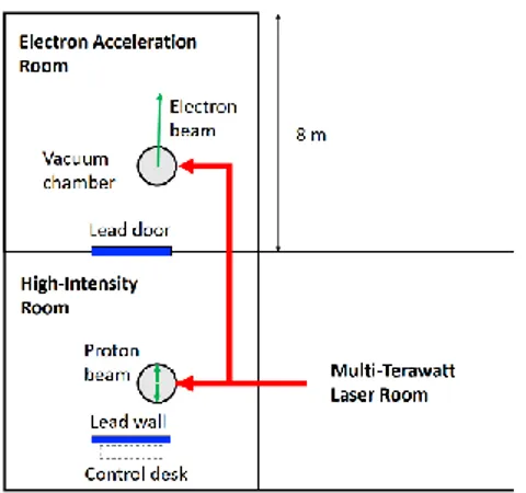
The inner and outer laboratories are separated by a 60-cm thick concrete wall, and the opening between the rooms is covered with a 13-cm thick sliding lead door. Each cylindrical experimental vacuum chamber is made of aluminum, is 120 cm in diameter, 60 cm high, and has 5 cm thick walls. The electron beam is generated in the center of the chamber, and propagates away from the door, towards the far end of the room. Radiation in the forward beam direction is absorbed in the far concrete wall, or in the soil outside the Electron Acceleration Room. In the High-Intensity Room, the protons are generated in the center of the chamber but stopped by the chamber walls. One control desk is used for all experiments and is placed behind a lead wall in the High-Intensity Room.
Figure 2.9: Layout of the experimental area at LLC. The laser room and the control
room are in the basement of the main building, while the Electron Acceleration Room is outside the main building in an underground bunker, which is sealed by a lead door. The electron beam propagates away from the main building.
10
Repetition rate and annual shot rate
Although the laser operates at 10 Hz, electron beams are produced at a maximum rate of 0.1 Hz. The reason for this is that gas used as the target to provide the plasma for the previous shot must be pumped out of the vacuum chamber prior to the next shot, which takes about 10 seconds. Before each experiment, the laser and auxiliary equipment must be prepared, which takes a few hours. When modifications are made to the setup, the vacuum chamber must be opened and then evacuated, which takes at least an hour. Therefore, in a typical day, 100–1000, but never more than 3000, laser shots are used in an electron acceleration experiment. Taking into account the time required for laser maintenance, and that the laser is also used for other experiments, it is estimated that electron beams are generated during less than 100 days per year, giving a maximum of 100,000 laser shots. To date, however, no more than 50,000 shots have been fired in any single year. Assuming an average charge of 100 pC per shot, this gives an estimated maximum total charge of 10 µC (6.2 · 1013
electrons) per year.
Proton beams can be produced at a maximum rate of 0.01 Hz (less than 1 shot/minute). The reason for this is that on each shot, the target foil is destroyed and a new foil has to be accurately positioned, with micrometer precision, prior to the next shot. This process typically requires at least one minute, often more. Moreover, the target foil holder typically contains less than 100 individual targets and to change it, the vacuum chamber must be opened. Therefore, in a typical day, less than 100, and never more than 300 laser shots are used for proton acceleration experiments. Assuming 5,000 shots per year, gives an estimated maximum number of 1014 protons per year, with
energies in the range of 1-10 MeV.
Since the electron beam is more energetic, and is generated at a higher repetition rate than the proton beam, electron acceleration experiments are expected to generate significantly more radiation annually than the proton acceleration experiments.
A laser-plasma acceleration experiment
As mentioned above, it is crucial to inject the electrons into the plasma wave at exactly the right moment. There are several ways in which this can be achieved experimentally. In the bubble regime, the plasma wave becomes severely nonlinear, and transverse wave breaking effects can result in self-injection of electrons. Unfortunately, self-injection is difficult to control, and it is not applicable when fine-tuning and control of the injected electron bunch are required.
An important part of the research program at the LLC is the development and improvement of different injection techniques. The aim in many experiments is to produce electron beams with high quality, i.e. with a narrow energy spread. This can be done by localizing the injection in space so that all the electrons are accelerated over the same distance and gain the same energy. Colliding pulse injection is one example of an injection technique. Here electrons are injected locally following the collision between the main pump pulse and a weaker, counter-propagating injection laser pulse (see Figs. 2.10 and 2.11).
It is also possible to modulate the plasma density profile and inject electrons in a density down-ramp, or in a shock-front in a supersonic gas flow. Another possibility is to use mixtures of gases with different ionization potentials. Each injection mechanism leads to electron beams with different characteristics. The results obtained at the LLC are summarized in Table 2.1.
11
Figure 2.10: The principle of colliding pulse injection. An intense laser pulse (the pump
pulse) drives a nonlinear plasma wave. In the injection phase, a weaker, counter-propagating laser pulse collides with the pump pulse and pre-accelerates background electrons. Pre-accelerated electrons are then trapped at the wake and accelerated by the plasma wave.
Figure 2.11: Setup and typical results from a colliding pulse injection experiment. A
small fraction of the main laser pulse is split off and used as an injection pulse. The two pulses collide in a supersonic gas jet at an angle of 150°. A series of linear translation stages is used for accurate adjustment of the optical path difference and spatial overlap of the two pulses. The electron beam is analyzed using a dipole magnet and a scintillator screen. The top right panel shows a raw image of the screen, while the bottom panel shows the analyzed electron spectrum. Here, the peak energy is 86 MeV and the energy spread is 3 MeV (3.5%), which is the limit of the spectrometer resolution.
Table 2.1: Parameter range for the electron beams obtained using different injection
mechanisms. The typical charge range is given per bunch (1 pC = 6.2·106 electrons). The
energy range is the average energy. The energy spread (ΔE/E) and divergence were determined at full-width at half-maximum. The parameters are taken from recently published articles authored by researchers working at the LLC.
Injection mechanism Charge [pC] Energy range [MeV] ΔE/E [%] Divergence [mrad] Publication Self-injection 10–100 50–200 10–100 5–10 Mangles et al., 2006; Hansson et al., 2014; Svensson et al., 2016 Ionization 5–50 50–200 100 10 Hansson et al., 2016a;
Desforges et al., 2016 Down-ramp 1–10 40–100 50 10 Hansson et al., 2015 Shock-front 1–10 40–100 5 5 Burza et al., 2013 Shock +
ionization 1–10 80–150 7 4 Thaury et al., 2015 Colliding pulses 1–10 40–100 3 3 Hansson et al., 2016b
12
3 Survey of published
radiological assessments for
high-power laser facilities
This chapter presents a summary of a selection of published studies on radiation fields and radiation protection measures for different laser-plasma systems. The studies were categorized according to the peak power delivered by the system: GW (109 W), TW
(1012 W) or PW (1015 W) lasers. The results for both laser–solid and laser–gas
interactions are given for each power class, except for GW lasers, for which reports were found for one facility, both dealing with laser–solid experiments. A study on the radiation environment at the LLC is presented separately in Chapter 4.
Figure 3.1 shows the distribution of ultra-high intensity laser facilities around the world. The studies summarized originate from the following facilities.
- The 1 GW laser system at the Pulsed Laser Center (CLPU), Faculty of Physics, University of Salamanca, Spain.
- The 25 TW laser system at the Prague Asterix Laser System (PALS) Research Centre, Prague, Czech Republic.
- The 100 TW laser system at the Laboratory for the Use of Intense Lasers (LULI), École Polytechnique, Paris-Saclay University, France.
- The 2 × 10 PW laser system, under construction at the Extreme Light Infrastructure-Nuclear Physics (ELI-NP) Research Centre, Romania.
Figure 3.1: Map showing the distribution of ultra-high intensity laser facilities around
the world. (Reproduced from the International Committee on Ultrahigh Intensity Lasers (ICUIL) World Map by Dr. C.P.J. Barty, from https://www.icuil.org/activities/laser-labs.html, retrieved October 24, 2017. Copyright 2015 ICUIL. Reprinted with permission.)
13
It should be emphasized that studies on radiation protection and shielding practices at high-intensity laser facilities are rather inhomogeneous and are only applicable for the specific conditions at each facility. However, these studies reveal that the generation of ionizing radiation is strongly dependent on the laser beam intensity and the type of laser–target interaction. Therefore, we have categorized the studies based on these parameters, as we believe this should give an adequate picture of the radiological environment at different types of facilities.
3.1 Gigawatt laser systems
Laser–solid interactions
Two studies have been published on laser–solid interactions at CLPU: High Electron
Doses from a GW Laser Interacting with Solid Aluminum Targets (Fonseca et al.,
2010a) and Measurement of radiation produced by ultra-short laser pulses interacting
with solid targets (Fonseca et al., 2010b). The authors report γ and electron radiation
measurements for a laser system with a power of 1 GW, interacting with a solid aluminum target. This system is a Ti:sapphire laser with a CPA amplifier that delivers pulses of 110 fs duration and an energy of 0.9 mJ at a repetition rate of 1 kHz. The intensity at the focus on the target was estimated to ~1016 W cm-2.
About 900,000 shots were fired during a period of 15 minutes. Thermoluminescence dosimeters (TLDs) and radiochromic films were used to measure the dose as a function of distance. The particle energies were determined based on these data and stopping powers in air. The authors concluded that the emitted radiation consisted mainly of electrons described by two Maxwell–Boltzmann distributions with energies of some tens of keV. In addition, a smaller, but not insignificant, component of photons produced by bremsstrahlung emission was measured.
The authors reported a maximum dose rate of 8.25 µSv/s, with no discrimination between doses from electrons or photons, at a zero-degree reflection angle and a distance of 30 cm from the target. The dose rate decreased to 0.25 µSv/s at an angle of 180°. The authors concluded that, even for a low-power laser system, the high repetition rate led to a significant amount of radiation, which should be considered when designing such systems. However, radiation with an energy of tens of keV can be easily shielded against, and thin shielding with a material of low atomic number would be sufficient to eliminate any hazards from both β and bremsstrahlung.
3.2 Terawatt laser systems
Laser–gas interactions
Olsovcova et al. (2014c) evaluated the radiological hazards from a high-repetition-rate, high-intensity laser at the PALS Research Centre in Prague in a study entitled:
Radiation Protection Aspects in the Vicinity of TW Class Laser Systems. The system
is a 25 TW Ti:sapphire laser that provides a peak power of 25 TW in pulses <40 fs, with an energy of about 1 J. Typical experiments at the facility based on electron acceleration from a gaseous target were studied, both theoretically and experimentally, in order to verify the adequacy of existing bulk shielding and radiological safety. The responses of personal dosimeters in pulsed radiation fields, for which these dosimeters are not designed, were also evaluated.
14
The Monte Carlo transport code FLUKA (for a description, see Chapter 4) was used to simulate the electron, photon and neutron fluences, and ambient dose equivalents. The electron beam was attributed a mean energy of 100 MeV, a divergence of 10° and 6·106 electrons per shot. The interaction chambers were modeled as spherical steel
shells with an outer diameter of 80 cm and a 1 cm thick wall. A sketch of the experimental arrangement is shown in Fig. 3.2. An activation study was also performed, in which a steel slab 1 cm thick was assumed to have been irradiated for 100 s by a 100 MeV electron beam. The induced radioactivity was calculated up to an hour after the end of irradiation.
Figure 3.2: Schematic view of the experimental arrangement at the PALS high-intensity
laser system. The interaction chamber was modeled as a steel chamber of diameter 80 cm and a 1 cm thick wall. A 15 cm thick brick wall with a 3 cm thick wooden door separated the control room from the experimental area.
Measurements were also performed with electronic personal dosimeters (Mk2 EPD 2.3, Thermo Scientific), TLDs and films (Foma Personal Monitoring Films). The dosimeters were positioned inside and outside the interaction chamber, in the experimental area and the laser control room, and exposed to radiation from 180 shots. The fluences simulated with FLUKA showed that most of the particles and photons were emitted in the forward beam direction; the highest value being close to laser–gas interaction point, as expected. The wall of the interaction chamber was predicted to offer effective shielding, and decreased the fluences by several orders of magnitude. Neutrons were produced, but their fluence was many orders of magnitude lower than those of electrons and photons. Simulated and measured doses for 180 shots at different positions in the experimental area are given in Table 3.1.
Table 3.1: Dose equivalents for 180 shots obtained from FLUKA simulations and TLD and film
measurements. The ranges of doses reflect the variation between different measurement positions.
Location FLUKA
[mSv] TLD [mSv]
Film [mSv] Photons Electrons Total
Interaction chamber
(IC) 2.3–42 0.8–34 0.1–18 9.1–16 9–33 Vicinity of IC 0.2 Not measured 1.7 0.00 1.7 Experimental hall ≤ 0.1 ≤ 0.3 ≤ 0.5 0.00 ≤ 0.5 Laser control room 0.00 Not measured 0.00 0.00 0.00
15
The simulations and responses of TLDs and films generally agreed well. Inside the interaction chamber the dose from γ-radiation constituted 1% to 50% of the total. The EPDs responded well and showed good agreement with the TLDs and FLUKA simulations, despite low expectations due to the short pulses and findings reported in another study (Borne et al., 2002). A possible explanation for the good agreement was suggested to be the distance to the EPDs, which the authors argued could be sufficient to prolong the pulse time.
The activity induced in the steel slab was low and consisted mainly of iron and vanadium isotopes (see Table 3.2). Activation products of air, 15O and 13N, were below
10-8 Bq cm-3.
Table 3.2: FLUKA simulations of the activity induced in a 1 cm thick steel slab, after
100 seconds of irradiation with a 100 MeV electron beam. Only the most dominant nuclides are specified.
Nuclide Half-life [min]
Induced activity [mBq cm-3] Time after irradiation 10 sec 10 min 60 min
53m Fe 2.58 5.0 0.4 0.00 53Fe 8.51 2.3 1.8 0.03 52 V 3.743 0.4 0.1 0.00 Others 1.1 0.5 0.17
The authors concluded that typical experiments at the laboratory would not pose any radiation risk to personnel or the public as long as access to the experimental hall is prohibited during operation. The authors also simulated a maximal operational scenario of 240 shots per day, for which the more exposed parts of the laser control room showed an annual dose of 0.5 mSv. It was therefore recommended that occupancy of this room be kept to a minimum. Their results indicated that the EPD response was promising and that these could provide a supplement to passive dosimeters, but it was suggested that further studies should be carried out on their performance in pulsed fields.
Laser–solid interactions
The study by Borne et al. in 2002, Radiation Protection for an Ultra-High Intensity
Laser, is one of the earliest published studies on radiation protection at high-intensity
laser facilities, and is cited by many others. Borne et al. presented a thorough radiological study of the vicinity of a 100 TW Ti:sapphire/Nd:glass laser facility at LULI in Paris. Different techniques were used to measure γ- and neutron radiation for different laser pulse energies and intensities on solid and semi-solid targets. Levels of activation and contamination were also investigated.
The LULI 100 TW laser system is based on the CPA technique applied to Nd:glass and Ti:sapphire amplifiers. The maximum energy the system can deliver is 30 J and 15 J with pulse durations of 300 fs and 350 fs, respectively. The maximum repetition rate is one shot every 20 minutes. The spherical experimental chamber is composed of stainless steel, and is 1 m in diameter with a mean wall thickness of 1 cm. It has several windows and entries made of glass or metal. Access to the chamber and the laser during shots on target is prevented by a dedicated safety system.
16
The laser irradiance in the study was about 1017–1019, resulting in a Maxwellian
distributed electron spectrum with a mean energy of 1.5 MeV. These electrons generate γ-radiation in the target and around the experimental setup. Γ and neutron radiation was measured around the chamber and in the surrounding areas for different laser shot configurations on solid and semi-solid (foam) targets. Table 3.3 lists the different configurations.
Table 3.3: Laser shot configurations for thetest series at the LULI 100 TW laser system
Energy [J] Num. of shots Target Thickness [µm]
14–20(a) 15 Teflon 175 25 Al 25 30 Au 20 < 5 80 Exploded CH 200 20 1 Au 100
(a) High-energy configuration
Doses from γ-radiation, expressed as ambient dose equivalents, were measured with TLDs at 50 positions, with two or three dosimeters at each position. After 70 shots with energies of 14–20 J on solid targets, which the authors called the high-energy configuration, some of the TLDs on the experimental chamber were removed. Thereafter followed another 80 shots with lower energy. Photographic films were exposed at some of the positions of the TLDs for comparison. A single shot of 20 J on a 100 μm thick gold foil was used to quantify the γ-dose close to the chamber from a full-power shot on a high-Z target. Ambient neutron dose equivalents from nuclear reactions, (,n), were measured with a bubble dosimeter positioned in contact with the chamber, discriminating thermal and fast neutrons. The response of personal dosimeters was also studied, despite the expectation that these would fail due to the extremely short pulses. In addition, activation and contamination measurements were performed by γ spectrometry and wipe tests on the chamber wall and inside parts of the setup.
The dose equivalents obtained from TLD measurements at different positions in contact with the experimental chamber and areas around the experimental set-up are presented in Table 3.4. Shots in the high-energy configuration delivered in general 90–95% of the doses, and the γ-emission peaked in the forward direction, in a 60° cone. The dose behind a 5 cm lead shield was reduced to 0.20 mSv. The doses on top of the chamber were about 7.5 mSv, which is 10 times higher than the doses below it. The results from photographic films and TLDs showed good agreement. Dose equivalents outside the area were all below 100 µSv, except for an area on the next floor, immediately above the chamber where a dose of 450 µSv was measured. It was concluded that measures should be taken to improve radiation safety, in terms of more shielding or prohibiting access to the area. The doses along the beam axis for the total of 150 shots were found to be 50–75 mSv. The mean energy of the γ-emissions was estimated to be 700 keV from attenuation calculations.
17
Table 3.4: Dose equivalents from γ-radiationat three different locations in contact with the experimental chamber. For surrounding areas, doses are given as the range between different positions. The distance given is from the target inside the experimental chamber.
Measurement
position Distance [m]
TLD γ- dose equivalents [mSv]
150 shots all targets 70 shots(a) Teflon, Al, Au
Experimental chamber 0.5 49 42 73 30 9 8 Experimental area 2.5–7 0.05–0.2 Adjacent rooms 3–6 0.03–0.1 Second floor 2–8 0.03–0.5
(a) High-energy configuration
The dose equivalents measured with TLDs and EPDs in contact with the experimental chamber, and neutron doses from bubble dosimeters are given in Table 3.5. Fast neutrons gave the highest dose, of 0.8 mSv, which was still 100 times less than γ-doses at the same position. Doses from fast neutrons were ten times higher than those from thermal neutrons. The EPDs gave no readings, as was expected, due to the short pulses (a few hundred femtoseconds). The measurements for one full-power shot showed a maximum dose of 0.5 mSv in the forward direction. This agreed well with the values of 30–40 mSv for 70 high-energy configuration shots presented above.
Table 3.5: Dose equivalents obtained from TLDs and EPDs, and bubble dosimeters for fast
neutrons (nfast) and thermal neutrons (nthermal). The distance given is from the target inside the
experimental chamber.
The results obtained with γ-spectrometry showed only nuclides from the natural background, and no activation products were identified for the chamber itself, parts of the internal setup, e.g., the target holder, and wipe tests.
The authors compared the dose equivalents determined in this test series with international exposure limits. It was assumed that the normal working conditions over a one-year period would be equivalent to five similar series of shots, i.e., 800 shots per year. Based on this assumption, the dose was found to be below 1 mSv per year, as specified in the ICRP 60 recommendations, at almost all positions. Doses up to 2.5 mSv per year were, however, estimated for working areas on the second floor, above the experimental chamber. The authors therefore deemed it necessary to install adequate biological shielding, or to restrict access to this area during laser operation. The doses within 2 m of the chamber rapidly exceeded the annual exposure dose limit, and it was concluded that the existing radiological classification of the experimental area and access restrictions during shots were justified. Doses from γ and neutron radiation in direct contact with the chamber could exceed 370 mSv and 2 mSv, respectively.
Distance (m)
γ-dose equivalents [mSv] Neutron dose equivalents [mSv]
TLD EPD nfast nthermal
0.5 40; 45; 82 < 1 0.4; 0.4; 0.8 0.04; 0.05; 0.08 1.2 6.0; 7.4 < 1 0.06; 0.07 0.007; 0.008
18
Finally, the authors concluded that their study had led to a quantitative evaluation of the radiological risks associated with different shot configurations, and that the amount of radiation depended on the laser energy and the nature of the target. Based on their findings, they were able to define protection and radiological controls for personnel and different areas of their facility. In addition, they confirmed that ultra-high intensity lasers can generate significant amounts of radiation, and that the radiological safety of personnel must be carefully considered when designing such facilities.
3.3 Petawatt laser systems
Laser–gas and laser–solid interactions
The Extreme Light Infrastructure (ELI), part of the European Strategy Forum on Research Infrastructures, will see the next generation of PW class facilities. It will be the world’s largest laser research facility, offering the most intense beamline system worldwide, and the first international user facility in beamline and laser research. Ultra-high intensity interactions will be explored, and radiation sources in an extraordinary energy range are foreseen: electron beams are expected to range between 1 and 50 GeV and protons from 100 MeV up to 3 GeV (Ferrari et al., 2013). The research centers will be placed at four different sites, three of which are: ELI-Beamlines in the Czech Republic, the ELI-Attosecond Light Pulse Source in Hungary, and ELI-NP in Romania. The fourth site is yet to be decided.
A number of studies on radiation protection have been carried out for ELI-NP (e.g., Ferrari et al., 2013a; Ferrari et al., 2013b; Olsovcova et al., 2014a; Popovici et al., 2015; Bechet et al., 2016, Mitu et al., 2016 and Popovici et al., 2017.) The main results of the study by Popovici et al. (2017) are summarized in this section.
In the study entitled: Shielding Assessment of High Field (QED) Experiments at the
ELI-NP 10 PW Laser System, Popovici et al. (2017) evaluated the bulk shielding that
has been constructed for experiments at ELI-NP in Romania. One of the goals of the study was also to investigate compliance with legal dose limits, and to investigate the effectiveness of a beam dump and solutions for muon shielding. The facility will host a high-intensity 2 × 10 PW laser system and record beam intensities of 1023–
1024 W cm-2 are expected, with energies of about 250 J per shot and a duration of <
20 fs, with up to one shot per minute. The beamlines will produce extremely high-energy γ-rays for different nuclear physics applications.
A completely different radiation environment is expected here, compared to other laser facilities, because of the extremely high power. Particles will be generated at energies above the threshold for electromagnetic and hadronic cascades and pion production. Therefore, the buildings have been designed in line with the principles of radiation protection for conventional high-energy accelerators. A controlled access system will be implemented to prevent any unauthorized or accidental entry during operation, and the room containing the interaction chamber and adjacent zones will be classified as controlled areas. The authors stated that well-documented radiation protection policies and practices have been used in the design of the facility and refer to the study by Fasso and Rokni (2009).
19
Figure 3.3: Sketch of the experimental area for the ELI-NP 10 PW laser system
surrounded by 2 m thick radiological protection walls (fixed concrete walls and movable concrete blocks). The interaction chamber, electron beam dump and muon shielding are indicated. The interaction chamber is made of an aluminum alloy, has 15 cm thick walls and is approximately 4.5 m wide with a height of 2.65 m. The beam dump is made of graphite, copper and tungsten embedded in heavy concrete. The suggested muon shielding has a length of 7 m and is filled with soil.
The shielding assessment was carried out using FLUKA simulations for the experimental area shown in Fig. 3.3, which is expected to yield the highest ambient dose equivalents. The authors claim that the radiation levels are expected to be the highest of all laser facilities worldwide. Early in the ELI project, source terms for different experiments were defined by carefully applying scaling laws and results from particle-in-cell (PIC) calculations. These were used in the building design to ensure adequate radiation protection. The experiments are still being designed, and the source terms are continuously updated and evaluated with regard to radiation protection. The main features of the source terms for five different experimental setups are given in Table 3.6.
Table 3.6: Source terms obtained through FLUKA simulations for specific experimental
configurations
Type of experiment Energy distribution Divergence No. of particles per shot
SE1 Electron laser wakefield acceleration
Gaussian, Emax= 38 GeV,
ΔE/E = 10% 3° 1.4·1010 SE2 Electron acc. in overdense
plasma
Relativistic Maxwellian, Thot = 116 MeV, cut-off
1.2 GeV
Isotropic 5.0·1012
SE3 Electron acc. in thick
target, 2 mm Au Similar to SE2 Pencil beam 5.0·10
12
SP1
Proton acc. in radiation pressure or breakout afterburner regimes
Gaussian, Emax= 500 MeV,
ΔE/E = 10% 5° 1.0·1012 SP2 Proton TNSA Uniform, 100 MeV 40° 6.0·1012
The total irradiation time was estimated to be 300 minutes per day, 250 days a year, with a laser repetition rate of one shot per minute. These were regarded as reasonable assumptions given that the parameters will be different in each experiment. Dose limits were set at 2 mSv for workers and 0.1 mSv for members of the public. This led
20
to an average dose equivalent rate of 1 µSv h-1 as a conservative design constraint for
occupational exposure, and 0.1 µSv h-1 for members of the public (assuming the same
person is exposed during the total irradiation period). In some less frequently occupied areas, where interlocking systems will be used on doors, rates up to 25 µSv h-1 were
considered acceptable. These areas were classified as controlled.
Some of the total dose equivalent rates simulated using FLUKA arising from the electron laser wakefield acceleration experiment (SE1) are presented in Table 3.7. The source term, consisting of a 38 GeV electron beam, will generate a bremsstrahlung spectrum extending from zero to the energy of the electrons. The photons produce a range of photonuclear reactions resulting in slow and fast neutrons, protons, muons, pions, kaons, etc., the most difficult of which to shield against are neutrons and muons2. Neutrons will be effectively shielded by the room’s concrete walls. It has
been suggested that a local external muon shield (7 m long) can be built composed of soil, which gives a reasonable balance between protection and cost when additional access restrictions are implemented. It was concluded that the dose rates were within the design dose rate constraints of 1 µSv h-1 for areas without access restrictions
outside the experimental area.
Table 3.7: Ambient dose equivalents obtained from FLUKA simulations of experiment SE1, a
38 GeV electron beam, and SP1, a 500 MeV proton beam with a Gaussian energy distribution. A maximum repetition rate of 60 shots per hour was assumed. All values are rounded to the nearest power of ten. Positions at the interaction chamber (IC), electron beam dump (BD) and muon shielding (MS) are given relative to the direction of the beam.
(a)Dose rate mainly due to muons
The equivalent dose maps obtained from the experiments on laser acceleration in thick targets (SE2 and SE3) for which the energy distributions and number of particles were similar (Thot = 116 MeV, cut-off 1.2 GeV) but different beam divergence (isotropic
vs. pencil beam), showed contrasting and very different spatial distributions. The authors attributed this to the influence of the experimental setup on the spatial dose distributions, despite the fact that similar particle energies are involved.
The strongest proton source term considered in the simulations arose from the SP1 experimental set-up (Table 3.6). The secondary particles will be created by inelastic interactions between the primary proton beam and the surrounding material, which will be followed by electromagnetic cascading. Different nuclear processes, e.g.,
2 The photon energy threshold for muon pair production is 211 MeV. Muons are also
produced in the decay of pions.
Position Experiment Before IC IC After IC BD Behind BD and wall [µSv h-1 ] [µSv h-1 ] [µSv h-1 ] [µSv h-1 ] [µSv h-1 ] Laser beamline SE1 1–10 10–106 106 10–108 1–10 (a) SP1 102–103 103–108 108 1–108 10-2 Roof SE1 ≤ 10 -2 ≤ 10-1 ≤ 10-2 ≤ 10-2 ≤ 10-3 SP1 10-3–1 10-3–1 10-2–6·100 10-3–1 10-3–10-1 Basement SE1 ≤ 10-4 ≤ 10-1 ≤ 10-1 10-3–10-1 < 10-4 SP1 10-2 10-4–1 1–2.5·101 1–2.5·101 ≤ 10-2
21
fission and evaporation, will produce secondary neutrons, protons, pions, kaons, heavy fragments and γ-rays. Table 3.7 also presents a selection of the authors’ FLUKA results for ambient dose equivalents.
The design dose constraints were not met at two locations; on the roof and in the basement, by factors of 6 and 25, respectively. A higher neutron fluence was seen here than with the SE1 experiment. The authors stated that these areas will be continuously monitored, and if elevated dose rates are found, the laser shot repetition rate could be decreased. Additional neutron shielding could also be added.
The aim of the SP2 experiment is to produce energies at the upper limit of previously reported TNSA experiments. The ambient dose equivalent rates were mostly within the design dose constraints, although there were some exceptions. The same reasoning was applied as in the previous case, i.e., that the laser shot rate could be reduced if elevated values were recorded. In addition, the access control system will prohibit occupancy of these areas during laser operation.
The authors concluded that the main types of ionizing radiation that will escape the shielding around the experimental area will be γ-rays and neutrons. Appropriate detectors should therefore be chosen to monitor the relevant radiation characteristics. The authors proposed two types of detectors: one for residual activity measurements positioned inside the experimental area, operating only when the laser beam is off, and another for pulsed field measurements positioned outside the experimental area and is always on. These detectors are described in more detail in the reports by Mitu et al. (2016) and Cernaianu et al. (2016).
It was also concluded that during experiments, the radiation fields around the interaction chamber will significantly exceed the relevant dose limits, and that a controlled access system will be necessary. Existing shielding was deemed to be sufficient except in the case of muons, which constituted the main radiation protection issue, and could escape from the experimental building. A local muon shield with appropriate dimensions and composition was therefore suggested.
3.4 Further reading
Additional studies on radiation protection and the characterization of radiation fields around high-intensity lasers are listed in Table 3.8, categorized according to laser power and type of interaction.