Doctoral thesis
As-cast AZ91D Magnesium Alloy
Properties: Effects of Microstructure
and Temperature
Hoda Dini
Jönköping university School of Engineering
Doctoral Thesis
As-cast AZ91D Magnesium Alloy Properties:
Effects of Microstructure and Temperature
Dissertation Series No.30 Copyright © 2017, Hoda Dini Published and Distributed by
School of Engineering, Jönköping University Department of Materials and Manufacturing SE-551 11 Jönköping, Sweden
Tel: +4636101000 www.ju.se
Printed by Inko AB, year2017
ABSTRACT
Today, there is an essential need for lightweight, energy-efficient, environmentally benign engineering systems, and this is the driving force behind the development of a wide range of structural and functional materials for energy generation, energy storage, propulsion, and transportation. These challenges have motivated the use of magnesium alloys for lightweight structural systems. Magnesium has a density of 1.74 g/cm3, which is almost 30% less than that of aluminium, one quarter of steel, and almost identicalto polymers. The ease of recycling magnesium alloys as compared to polymers makes them environmentally attractive, but their poor mechanical performance is the primary reason for the limited adoption of these alloys for structural applications.
The Mg-Al-Zn alloy AZ91D exhibits an excellent combination of strength, die-castability, and corrosion resistance. However, its mechanical performance with regard to creep strength, for example, at evaluated temperatures is poor. Moreover, very little is known about the correlation between its mechanical properties and microstructural features. This thesis aims to provide new knowledge regarding the role played by microstructure in the mechanical performance of the magnesium alloy. The properties/performance of the material in relation to process parameters became of great interest during the investigation.
An exhaustive characterisation of the grain size, secondary dendrite arm spacing (SDAS) distribution, and fraction of Mg17Al12 was performed using optical and electron backscatter diffraction (EBSD).
These microstructural parameters were correlated to the offset yield point (Rp0.2), fracture strength, and
elongation to failure of the material. It was proposed that the intermetallic phase, Mg17Al12, plays an
important role in determining the mechanical and physical properties of the alloy in a temperature range of room temperature to 190°C by forming a rigid network of intermetallic. The presence of this network was confirmed by studying the thermal expansion behaviour of samples of the alloy containing different amounts of Mg17Al12.
A physically based constitutive model with a wide validity range was successfully adapted to describe the flow stress behaviour of AZ91D with various microstructures. The temperature-dependent variables of the model correlated quite well with the underlying physics of the material. The model was validated through comparison with dislocation densities obtained using EBSD.
The influence of high-pressure die-cast parameters on the distortion and residual stress of the cast components was studied, as were distortion and residual stress in components after shot peening and painting. Interestingly, it was found that intensification pressure has a major effect on distortion and residual stresses, and that the temperature of the fixed half of the die had a slight influence on the component’s distortion and residual stress.
Keywords: Magnesium; Magnesium Alloy; AZ91D; High-Pressure Die-Casting; Mechanical Property;
SAMMANFATTNING
Numera finns det ett väsentligt behov av lätta, energieffektiva och miljövänliga tekniksystem. Detta behov är drivkraften för utveckling av ett brett utbud av material för energigenerering, energilagring, framdrivning och transport. Dessa utmaningar motiverade användningen av magnesiumlegeringar för lättviktskonstruktioner. Magnesium har en densitet på 1,74 g/cm3, vilket är ca 30% lägre än föraluminium, en fjärdedel av densiteten för stål och nästan i nivå med många polymerer. Då magnesiumlegeringar dessutom är lätta att återvinna, jämfört med polymerer, gör det dem miljömässigt attraktiva. Låga mekaniska egenskaper är den främsta orsaken till begränsad användning av dessa legeringar för lastbärande tillämpningar.
Mg-Al-Zn-legeringen AZ91D uppvisar en utmärkt kombination av styrka, gjutbarhet och korrosionsbeständighet. Dess mekaniska egenskaper vid förhöjd temperatur, som tex kryphållfasthet, är låga. Dessutom är korrelationen mellan mikrostruktur och mekaniska egenskaper oklar. Denna avhandling syftade till att ge ny kunskap om mikrostrukturens roll för magnesiumlegeringars mekaniska egenskaper. Slutligen var materialets egenskaper i förhållande till processparametrar vid tillverkningen av stort intresse.
En omfattande karaktärisering av kornstorleks-, sekundära dendritarmavstånds (SDAS)-fördelning och fraktion av Mg17Al12 utfördes med hjälp av optisk mikroskopering och diffraktion av bakåtspridda
elektroner (EBSD). Mikrostrukturen korrelerades till sträckgränsen (Rp0.2), brottstyrkan och
brottförlängningen. Det föreslogs att den intermetalliska fasen, Mg17Al12, spelar en viktig roll vid
bestämning av legeringens mekaniska och fysikaliska egenskaper vid temperaturintervall från rumstemperatur upp till 190°C genom att bilda ett styvt nätverk av intermetaller. Uppkomsten av ett sådant nätverk stöddes genom en studie av den termiska expansionen av legeringen för olika fraktioner av Mg17Al12.
En fysikalisk konstitutiv modell med ett brett giltighetsområde användes framgångsrikt för att beskriva det plastiska flytbeteendet hos AZ91D för olika mikrostrukturer. De temperaturberoende variablerna i modellen korrelerade ganska väl med materialets underliggande fysik. Modellen validerades genom att jämföra dislokationstätheten som predikterades av modellen och den med EBSD uppmätta dislokationstätheten.
Påverkan av pressgjutningsparametrar på geometrisk tolerans och restspänning hos de gjutna komponenterna studerades. Vidare studerades geometrisk tolerans och restspänning av komponenter efter pening och målning. Intressant nog hade eftermatningsfasen en stor effekt på geometrisk tolerans och restspänningar. Dessutom hade temperaturen på den fasta formhalvan av verktyget även ett visst inflytande på komponentens geometriska tolerans och restspänning.
Nyckelord: Magnesium; Magnesiumlegering, AZ91D; Pressgjutna, Mekanisk Egenskap, Mikrostrukturkarakterisering, Fysikalisk Modellering; Flytspänning; Dislokationer; Geometrisk Tolerans; Restspänning
ACKNOWLEDGEMENTS
I would like to express my deep respect and gratitude to Prof. Anders Jarfors, my primary supervisor, for his invaluable, fruitful, and constructive suggestions and guidance, which have enabled me to overcome all of the problems and difficulties that have arisen while carrying out the present work. He stayed with me and ensured that I was constantly motivated and stimulated. I feel fortunate to have enjoyed his support and involvement, and this is virtually impossible to express in words.
My appreciation also extends to my co-supervisor, Assistant Prof. Nils-Erik Andersson, who provided inspiration and helped me to understand the critical aspects of the work. The lessons learnt from him about considering problems from different perspectives were invaluable. I would like to acknowledge Dr. Ehsan Ghassemali for his help with EBSD experiments and suggestions and advice. I am also thankful to Associate Prof. Ales Svoboda for his guidance with modelling.
Thanks, are due to the current and former technical staff at the Jönköping University,
Department of Materials and Manufacturing, Toni Bogdanoff, Lars Johansson, Esbjörn Ollas, Peter Gunnarsson, and Jacob Steggo for their assistance. I thank Jörgen Bloom for his great assistance with experiments carried out at Husqvarna AB.
The industrial partner Husqvarna AB and Pär Guth are acknowledged for providing the necessary data and materials.
The Knowledge Foundation (KK-stiftelsen) is acknowledged for their financial support as part of the CompCast project (Dnr 20100280).
I sincerely thank the colleagues and friends at Jönköping University who made my doctoral studies more fun and joyful. All of the departmental conferences, lunches, after-work sessions, and fikas that we had played an important role in the writing of this thesis, although this might look contradictory.
I am grateful for the support and motivation provided by my family – especially my parents, Mohsen and Afsaneh, my sister, Nilufar, and my brother, Saber – and thank them for always believing in me. Last but definitely not least, I would like to thank Reza for his perspective and sense of balance, and for helping me to enjoy breaks from the thesis.
SUPPLEMENTS
The following supplements constitute the basis of this thesis:Supplement I H. Dini, N. Andersson, A.E.W. Jarfors; ‘Effects of Microstructure on
Deformation Behaviour of AZ91D Cast Alloy’. TMS 2014, 143rd ANNUAL MEETING & EXHIBITION. February 16-20, San Diego, CA, USA.
Dini was the main author and performed the experimental work. Andersson and Jarfors contributed with supervision and advice on the experiments and methods of analysis.
Supplement II H. Dini, N. Andersson, E. Ghassemali, A.E.W. Jarfors; ‘Microstructural
Scale Effects on Thermal Expansion Behaviour of Cast AZ91D’. Magnesium Technology 2015, pp. 361-365. TMS 2015. March 15-19, Orlando, FL, USA.
Dini was the main author and performed the experimental work. Andersson and Jarfors contributed withsupervision and advice on the experiments and methods of analysis. Ghassemali assisted with the EBSD results.
Supplement III H. Dini, N. Andersson, A.E.W. Jarfors; ‘Effect of Mg17Al12 Fraction on
Mechanical Properties of Mg-9%Al-1%Zn Cast Alloy’. Metals, 2016, Vol. 6.10, p. 251.
Dini was the main author and performed the experimental work. Andersson and Jarfors contributed with supervision and advice on the experiments and methods of analysis.
Supplement IV H. Dini, A. Svoboda, N. Andersson, E. Ghassemali, L. Lindgren, A.E.W.
Jarfors; ‘Modeling the Deformation Behavior of As-Cast AZ1D Including
the Effect of The Cast Microstructure’. Proceedings of PLASTICITY ’17: The Twenty Third International Conference on Plasticity, Damage, and Fracture (NEAT PRESS, P.O. Box 136, Fulton, Maryland 20759-0591, USA) (2017), pp. 37-39.
Dini was the main author and performed the experimental work. Svoboda and Lindgren contributed with adaptation and optimisation of the model. Ghassemali assisted with the EBSD results. Andersson and Jarfors contributed with supervision and advice on the experiments and methods of analysis.
Supplement V H. Dini, A. Svoboda, N. Andersson, E. Ghassemali, L. Lindgren, A.E.W. Jarfors; ‘Optimization and Validation of a Dislocation Density Based Constitutive Model for As-Cast Mg-9%Al-1%Zn’; Materials Science and Engineering: A, Volume 710, 5 January 2018, Pages 17–26.
Dini was the main author and performed the experimental work. Svoboda and Lindegren contributed with adaptation and optimisation of the model. Ghassemali assisted with the EBSD results. Andersson and Jarfors contributed with supervision and advice on the experiments and methods of analysis.
Supplement VI H. Dini, N. Andersson, A.E.W. Jarfors; ‘Effect of Process Parameters on
Distortion and Residual Stress of High-Pressure Die-Cast AZ91D Components’; International Journal of Metalcasting (2017), ISSN: 2163-3193, DOI: 10.1007/s40962-017-0186-z.
Dini was the main author and performed the experimental work. Andersson and Jarfors contributed with supervision and advice on the experiments and methods of analysis.
Supplement VII H. Dini, N. Andersson, A.E.W. Jarfors; ‘Effect of process parameters on
distortion and residual stress in high pressure die cast AZ91D components after shot peening and painting’; submitted manuscript.
Dini was the main author and performed the experimental work. Andersson and Jarfors contributed with supervision and advice on the experiments and methods of analysis.
The following article is not included in this thesis:
Supplement VIII M. Zamani, H. Dini, A. Svoboda, L. Lindgren, S. Seifeddine, N. Andersson,
A.E.W. Jarfors; ‘A dislocation density based constitutive model for as-cast Al-Si alloys: Effect of temperature and microstructure’; International Journal of Mechanical Sciences 121(2017): 164-170.
Zamani was the main author. Dini, Svoboda, and Lindegren contributed with development and optimisation of the model. Seifeddine, Andersson, and Jarfors contributed with supervision and advice on the methods of analysis.
TABLE OF CONTENTS
CHAPTER 1 INTRODUCTION ... 1 1.1 BACKGROUND 1 1.2 MAGNESIUM ALLOYS 2 1.3 MG-AL-BASED ALLOYS 3 1.4 HIGH-PRESSURE DIE-CASTING 61.5 DEFORMATION MECHANISMS OF MAGNESIUM ALLOYS 9
1.6 MECHANICAL PROPERTIES OF MG-AL ALLOYS 11
1.7 DEFORMATION MODELING OF MAGNESIUM ALLOYS 12
CHAPTER 2 RESEARCH APPROACH ... 21
2.1 PURPOSE AND AIM 21
2.2 RESEARCH DESIGN 22
2.3 MATERIAL AND EXPERIMENTAL PROCEDURE 25
CHAPTER 3 SUMMARY OF RESULTS AND DISCUSSION ... 33
3.1 CASTING AND MICROSTRUCTURAL SCALE 33
3.2 MECHANICAL PROPERTIES AND MICROSTRUCTURAL SCALE 36
3.3 THERMAL EXPANSION BEHAVIOR AND MICROSTRUCTURAL SCALE 42
3.4 MODELING THE PLASTIC FLOW OF AZ91D 46
3.5 EFFECT OF HPDC ON DISTORTION AND RESIDUAL STRESS 55
CHAPTER 4 CONCLUDING REMARKS ... 65
CHAPTER 5 FUTURE WORK ... 67
REFERENCES ... 69
CHAPTER 1
INTRODUCTION
CHAPTER INTRODUCTIONThis chapter commences with a background on magnesium cast alloys, with a special focus on the AZ91D alloy and its general microstructural features and mechanical properties. A constitutive model, which was based on the evolution of immobile dislocation and used to describe the plastic flow of the alloy, is introduced.
1.1 BACKGROUND
Weight-reduction efforts are being driven by higher fuel costs, the need for greater efficiency, and reductions in CO2 emissions for environmental reasons [1-3]. Countries such as Germany,
the UK, France, the USA, South Korea, and Japan are currently undertaking major national research and development initiatives [1, 4-7]. At least half of Sweden's exports depend on the development of lightweight materials [8], and so it is essential that a national, concerted effort to promote lightweight solutions is made in order for growth in key strengths to occur. The focus of lightweight solutions is on reducing weight through improved properties and new, innovative solutions [3]. Hence, studying the properties/performance of materials and the relationships between these and processing parameters and microstructures is of primary interest. Metallic materials such as aluminium and magnesium, as well as composites and sandwich materials, have tremendous potential in relation to the development of lightweight materials with regard to improving material properties and developing manufacturing processes and component solutions.
In recent decades, finding materials that are lighter than aluminium has become increasingly important, as have producing complex structures and reducing costs [9]. Magnesium is an attractive alternative in the fields of advanced materials for aircraft systems, the automotive industry, and hand-held tools – for use both today and in the future.
Casting is an inexpensive, low-emission manufacturing technique that facilitates the production of components in a wide range of sizes and with complex geometries, and thus plays a crucial role in the production of lightweight technologies. High-pressure die-casting is the preferred manufacturing process for the magnesium alloy components used by the automotive industry, as well as in numerous other applications, including the components used in hand-held tools [10].
In Europe, the increasing usage of magnesium as a lightweight structural material is being led by the Volkswagen Group, as well as Daimler, BMW, Ford, and Jaguar [3, 9, 11, 12]. At present, approximately 14 kg of magnesium is used in the VW Passat and Golf platforms, which utilise AZ91D for transmission casings, offering a 20-25% weight saving over aluminium [13]. For
Husqvarna AB, a Swedish outdoor power tool manufacturer, it is important to be able to manufacture products that are as light as possible and still deliver satisfying performance. Many of their products are carried by users on a daily basis, and so the company is always seeking new materials with high specific strength for use in both engines and cutting components. Today, Husqvarna AB uses AZ91D for applications such as crankcases.
Although magnesium castings are being used in a growing number of structural applications, the amount of research and development that has been carried out on these alloys is very small in comparison to investigations of aluminium alloys. The main challenge to the widespread usage of cast magnesium alloys as it comes to performance without weight increase requires improved strength at elevated temperatures [14].
This thesis is connected to the development of sustainable lightweight solutions for the future. Its overall goal is to communicate an improved understanding of the relationship between the microstructure and manufacturing processes of magnesium alloys, and to explain how this will affect the final product’s processability and properties.
This chapter provides general information about magnesium alloys and their manufacturing processes, microstructures, and properties. In the last section of this chapter, the physically based model that was adopted in this work to correlate the microstructural and mechanical properties of the material is introduced.
1.2 MAGNESIUM ALLOYS
Magnesium alloys have the lowest density (less than 1.8 g/cm3) of all structural metals, and their
increased use in automobile and aircraft parts has resulted in increases in energy efficiency through weight saving [15]. Magnesium is also the eighth most abundant element on Earth, and is easy to machine and potentially recyclable [16]. Its poor creep properties above 120°C are the primary obstacle to the broader use of magnesium alloys in automotive systems [17]. Enhancing the creep resistance of magnesium alloys has therefore been the subject of various research projects, which have sought to explore alloy composition [18-20]. The most widely used alloying element is aluminium, which is relatively inexpensive and has a low density and strong strengthening effect on magnesium. Hence, most commercial magnesium alloys are based on the Mg-Al system, with small additions of other alloying elements such as zinc, manganese, silicon, and rare earth elements to meet certain application requirements.
Although wrought magnesium alloys have higher mechanical strength than as-cast ones, they exhibit higher mechanical anisotropy, which is detrimental to forming processes. Moreover, the processing of wrought magnesium alloys into their final shape is more complex [21]. Hence, magnesium components are generally produced by casting [22, 23], as this is the most cost-efficient process. However, the poor mechanical performance of as-cast magnesium alloys is a concern in relation to their applications, and is largely due to the presence of porosity and microstructural inhomogeneities such as variation in grain size and phase distribution [24-29]. Hence, attempts utilising both experimental [25-31] and modelling [25, 32-35] approaches have been made to relate microstructure to mechanical performance in magnesium casting. However, and despite these studies, a large scatter in data has been observed, which means that a significant effort is still required to establish a quantitative relationship between the microstructure and mechanical properties of magnesium alloys.
In conclusion, further work is required in order to i) understand the clear correlation between the microstructural features and mechanical behaviour of magnesium alloys and use a modelling tool to predict these behaviours; ii) optimise manufacturing techniques to improve the quality of cast magnesium parts.
1.3 MG-AL-BASED ALLOYS
Aluminium is alloyed with magnesium to increase its strength, castability, and corrosion resistance. The maximum solid solubility of aluminium in magnesium at 437°C is 12.7 wt% (Figure 1), decreasing to around 2% at room temperature (RT). Hence, an incoherent, coarse precipitate phase of the Mg17Al12 is formed following precipitation-hardening treatment [36].
To improve fluidity and room-temperature strength and reduce the corrosive effect of iron and nickel, zinc is often added to Mg-Al alloys. However, the addition of zinc in concentrations of greater than 1.0-1.5% to magnesium alloys consisting of 7-10% aluminium results in a hot cracking effect [36].
Manganese is another element that is alloyed with both Mg-Al and Mg-Al-Zn alloys to reduce impurities from iron and other heavy metals and turn them into Al-Mn-Fe intermetallic compounds, which may settle down during alloy production. The concentration of magnesium strongly depends on the aluminium concentration in the Mg-Al-Zn alloy, as the solubility of manganese in liquid magnesium sharply decreases with increasing aluminium content [36].
AZ91D (9% aluminium, 1% zinc) is one of the most common alloys in the Mg-Al-Zn alloying system. The microstructure and phase transformation that takes place during the solidification of AZ91D have been studied [38-40]. It has been revealed that microstructure of as-cast AZ91D constituents of hypoeutectic Mg-Al solid solutions, eutectic Mg-Al supersaturated solid solutions, and Mg17Al12 phases. These phases were obtained under non-equilibrium
solidification conditions.
Under equilibrium conditions, AZ91D should solidify with the formation of only hypoeutectic Mg-Al solid solution (Figure 1). However, the slow diffusion of aluminium under non-equilibrium solidification conditions leads to the formation of eutectic Mg17Al12 phases and an
aluminium-rich eutectic Mg-Al solid solution [41].
During non-equilibrium solidification it is assumed that, at the interface of the liquid/solid, each phase has the chemical composition identified from the equilibrium phase diagram in Figure 1; although diffusion does not occur in the solid, the composition of the liquid is uniform due to convection [42].
The morphology of a eutectic structure formed under non-equilibrium cooling conditions is different to that of a typical eutectic morphology formed through eutectic solidification [43]. Here, a divorced eutectic structure is formed in place of the typical lamellar eutectic morphology [44].
During rapid solidification, the eutectic phase of Mg17Al12 can form as a large, separate particle
with different shapes around the primary Mg-Al solid solution. It was found that the aluminium content of the Mg-Al solid solution can vary between 3-4% in the bulk and greater than 10% in the vicinity of the Mg17Al12 phase. Due to the slow cooling rate of ingot casting,
discontinuous precipitation can also take place in the solid state. However, no discontinuous precipitation occurs during die casting due to the high cooling rate [42]. The microstructure of die-cast AZ91D alloys consists of hypoeutectic Mg-Al solid solution grains along with eutectic Mg17Al12 particles, surrounded by islands of eutectic Mg-Al supersaturated solid solution [10,
42, 45]. Figure 2 shows the solidification sequences of AZ91D during ingot casting and die casting.
The solidification sequences during the ingot casting of AZ91D alloys are as follows: Solidification of hypoeutectic magnesium solid solution from molten liquids starts at 595°C, and is followed by the formation of the first Mg-Al solid solution crystals, which are approximately 1.5% aluminium. As the alloy cools, hypoeutectic Mg-Al solid solution crystals increase in size, with each layer of atoms that is added to the crystal surface being richer in aluminium than preceding ones. When a temperature of 470°C is reached (the point at which freezing would be complete, according to the equilibrium diagram) the crystals are approximately 1.5% aluminium at their centres and 9% on their surfaces. Thus, the average composition is somewhere between 1.5 and 9% aluminium, although freezing is not yet complete. Further cooling increases the size of the hypoeutectic magnesium solid solution crystals, and the chemical composition of the surfaces of the crystals reaches roughly 12% aluminium when the eutectic temperature of approximately 437°C is achieved. At this temperature, the growth of hypoeutectic magnesium solid solution is terminated, and the grains exhibit aluminium-rich and -poor regions [36]. Hence, the growth of Mg-Al solid solution is completed at 437°C, and as the liquid reaches eutectic temperature it solidifies as two phases: eutectic Mg-Al solid solution and Mg17Al12 intermetallic. Depending on the subsequent cooling
rate of the solid state, the eutectic magnesium solid solution may experience a discontinuous decomposition through the formation of Mg17Al12 intermetallic in lamellar form due to
decreasing aluminium solubility in Ma-Al solid solution, or remain as a supersaturated solid solution at RT due to the slow diffusion rate of aluminium in magnesium. Accordingly, cooling rate has an effect on grain size, secondary dendrite arm spacing (SDAS), and the fraction of Mg17Al12. Figure 3 shows the typical microstructure of AZ91D.
Figure 3. Microstructure of AZ91D. Mg17Al12
Primary
α
1.4 HIGH-PRESSURE DIE-CASTING
Die casting is an efficient manufacturing process that is used to mass produce components in a wide range of shapes with great accuracy and consistent replication. Die casting produces cast parts with smooth surfaces that do not require further machining.
In high-pressure die casting (HPDC), molten metal is injected under high pressure and at high velocity into a die to rapidly fill it. The die absorbs the stresses of the injection and dissipates the heat of the metal. The velocity and acceleration of the metal are controlled by a hydraulic system so as to optimise flow and the forces experienced by the metal as it fills the cavity and solidifies [46].
The variety of die-casting systems is the result of trade-offs in terms of the fluid flow of the metal. There are two primary types of die-casting process: cold and hot chamber.
Cold-chamber machines are preferred for casting alloys with higher melting points, such as aluminium, copper, and some ferrous alloys. This process separates the molten metal reservoir from the actuator for most of the process cycle (see Figure 4). Hot-chamber machines are used for alloys with low melting points (such as magnesium alloys), as the molten metal is held in a furnace containing a gooseneck chamber (see Figure 5). At the beginning of the cycle a piston is retracted, allowing the chamber and gooseneck to fill with molten metal. The piston is activated and the metal is plunged into cylinder and melt flows through the gooseneck and into the die through a spreader and gate.
The HPDC process cycle includes five main stages: (i) Filling of the runner and bringing the molten metal to the feeding gate at a low velocity in order to avoid turbulence. The velocity of the plunger in this stage is the ‘first-phase injection speed’. (ii) Filling of the casting cavity at very high velocity to avoid premature solidification at the gate. The velocity of the plunger in this stage is the ‘second-phase injection speed’. (iii) The solidification phase, with high cooling rates. (iv) High pressure is applied during the intensification stage to balance the solidification shrinkage and minimise the amount of air trapped inside the cast part. (v) The ejection phase, wherein the cast part is removed and the die halves are sprayed and repositioned so as to be ready to repeat the cycle. Figure 6 illustrates the various phases of a HPDC process based on the plunger’s travel and pressure over time.
Quality control in relation to the entire cycle is primarily conducted through the various process parameters, such as initial melt and die temperature, first- and second-phase injection speed, intensification pressure, phase duration, etc. Studying, characterising, and classifying the various die-casting parameters and their influence on the properties of cast objects is necessary in order to solve many of the problems that relate to magnesium casting and promoting its use in state-of-the-art industries.
One of the most common defects in HPDC components is porosity, which has an adverse effect on mechanical properties. Porosity in die castings can be caused by either entrapped gases or solidification shrinkage. It has been reported that high intensification pressure tends to reduce the porosity level, and that a slow first-phase injection speed in combination with a short plunger stroke generally results in less porosity [47].
The other defect in HPDC components is distortion (warping) of the casting. This usually occurs during the cooling phase due to the reduced cooling time of the process and high thermal gradient of the cast product. During solidification, the contraction of the casting is constrained by the die, which may result in residual stresses and complex spring back during the extraction of the product from the die. For more complex castings, non-uniform cooling conditions may create plastic strain that results in permanent distortion.
Moreover, residual stresses may arise and evolve as a result of a wide variety of post-treatment processes, such as shot peening and paint-bake cycles. Shot peening is regarded as an effective method of improving the fatigue strength of components by inducing compressive residual stress through plastic deformation of a surface. A surface in which tensile residual stress has been induced by the casting process will be more prone to fatigue failure than a surface that has experienced compressive residual stress.
On the other hand, if substantial residual stress exists in a casting this may cease at high temperatures, resulting in partial distortion. The distortion that can occur during the paint-bake cycle when the temperature of a component exceeds 200°C can lead to residual stress. As the temperature reached during paint-bake cycles exceeds those that have been shown to initiate creep behaviour in Mg-Al alloys, it is feasible that residual stresses present prior to a paint-bake cycle could cause dimensional changes in components.
Porosity in cast products is a well-studied phenomenon [48-52], and component distortion resulting from temperature gradients during cooling, shot peening, and paint-bake cycles remains a critical issue. A more nuanced understanding of residual stress distribution and the distortion pattern of magnesium cast parts could, through improved process control and better die design, reduce the deviation from design specifications that occurs, simultaneously improving productivity and reducing costs. Specifying the appropriate set of process parameters in order to create a high-quality HPDC product is a key concern for engineers and researchers.
Figure 5. Hot-chamber HPDC machine [46].
Figure 6. Curves for (a) plunger travel and (b) plunger pressure against time, indicating the various phases of a HPDC process [46].
1.5 DEFORMATION MECHANISMS OF MAGNESIUM ALLOYS
According to the von Mises yield criterion [23], more than five independent slip systems are needed for metals to deform uniformly and without failure at grain boundaries. Magnesium alloys have a hexagonal closest packed (HCP) structure, and so a limited number of slip systems are available to accommodate plastic deformation. At RT, magnesium alloys have four independent slip systems, with the remaining deformation accommodated by twinning. However, additional slip systems become active at elevated temperatures, providing sufficient independent systems and thus improving ductility.
1.5.1 Role of slip in deformation
Figure 7 shows the slip planes (basal, prismatic, and pyramidal) of magnesium alloys [23, 53]. Slip occurs when a resolved shear stress on a slip plane reaches the critical value for that system. At RT, the critical resolved shear stress (CRSS) is much greater for a non-basal slip system than a basal slip system. Hence, magnesium can be deformed easily within its basal planes at RT. Only two independent slip systems exist along slip direction 〈112�0〉 (see Table 1). Pyramidal 〈𝑎𝑎〉 slip produces shape change that is identical to that produced by combined basal slip and prismatic 〈𝑎𝑎〉 slip; here, the resulting number of independent slip systems in all three deformation modes is still four [23], and thus cannot accommodate deformation in direction 〈𝑐𝑐〉 in order to fulfil the von Mises criterion. Thus, other non-basal slip systems with a c-direction component (Table 1) should be activated [54], or the deformation should occur by twinning [53].
Figure 7. Unit cell and slip planes in magnesium [53].
At temperatures of above 200°C, the critical resolved shear stress for non-basal systems rapidly decreases, and the secondary {11�00}〈112�0〉 prismatic and {11�01}〈1120〉 pyramidal slip systems (see Table 1) become active. The larger Burgers vectors of (𝑐𝑐 + 𝑎𝑎) and small pyramidal plane distance at RT make the activation of pyramidal slip systems quite difficult, but increasing the temperature facilitates this somewhat [54]. These additional slip planes explain the increasing ductility at elevated temperatures.
Table 1. Independent dislocation systems in HCP metals [53].
Direction Plane Notation independent modes Number of
〈𝑎𝑎〉 Basal {0002}〈112�0〉 2 〈𝑎𝑎〉 Prismatic {11�00}〈112�0〉 2 〈𝑎𝑎〉 Pyramidal, 1st order {11�01}〈112�0〉 4 〈𝑎𝑎〉 + 〈𝑐𝑐〉 Pyramidal, 2nd order {101�1}〈112�3�〉 4 〈𝑎𝑎〉 + 〈𝑐𝑐〉 Pyramidal, 2nd order {21�1�1}〈112�3�〉 4 〈𝑎𝑎〉 + 〈𝑐𝑐〉 Pyramidal, 2nd order {112�2}〈112�3�〉 4 1.5.2 Deformation by twinning
Twinning is an important deformation mechanism in HCP materials at RT, wherein a portion of the original crystal takes up a new orientation as a result of shearing, producing a mirror image of the parent crystal [55].
In HCP metals, tension or compression of the c axis, which results in elongation, or shortening of the c orientation, can activate twinning in the form of either extension or compression twinning. The plane {101�2} has been identified as the extension twin plane in magnesium. The crystal structure of the twinning part is the mirror image of the initial crystal with respect to the twinning plane, and leads to a rotation of 86.3°of the basal planes. This rotation may activate a new set of deformation systems, resulting in an entirely different set of deformation systems than the initial crystal experienced. Compression twinning has been observed on the plane {101�1}. This twinning mode leads to a 56° difference with the initial basal planes. The deformation system that occurs after compression twinning can increase the resolved shear stress on the extension twinning system, and so extension twinning can occur inside the initial twin. This results in a 37o rotation with respect to the initial crystal basal planes, as part of a
mechanism called ‘double twinning’. Figure 8 shows the rotation of basal planes due to twinning
Figure 8. Schematic illustration of a) the initial material with crystallographic directions c and a1; , b) lenticular of tensile twin, c) compression twinning, d) double twinning [56].
1.6 MECHANICAL PROPERTIES OF MG-AL ALLOYS
As is discussed above, the microstructure of as-cast Mg-Al in its initial state consists of solid solution and Mg17Al12 phases. The Mg17Al12 phases precipitate finely at grain boundaries,
increasing the strength of the material by suppressing basal slip [57]. These precipitated Mg17Al12 phases are perpendicular to the basal plane [58] (the main slip system of α-magnesium
matrices) and make the dislocating movement more difficult, increasing the strength of the alloy [59].
The primary challenge in the application of Mg-Al-based alloys is their poor mechanical properties at high temperatures and, more particularly, low creep resistance at temperatures above 120°C. It has been found [10, 20, 60-62] that the low creep resistance of Mg-Al-based alloys is the result of the poor thermal stability of the Mg17Al12 phase. Zhu et al. [30] reported
that Mg17Al12 precipitates tend to coarsen at elevated temperatures, thus losing their
strengthening effect. Discontinuous precipitation can result in the grain boundary sliding at elevated temperatures. The Mg17Al12 phase at grain boundaries may decompose at elevated
temperatures, increasing the aluminium content in these regions and thus causing failure [59]. Moreover, it has been reported that micro cracks may nucleate at the interface of Mg17Al12 and
the magnesium matrix due to the incompatible body-centred cubic (BCC) structure of Mg17Al12
and the HCP structure of the matrix. This leads to the alloy having limited ductility [59]. However, it has been reported that temperatures of lower than 120°C are insufficient to soften Mg17Al12 particles or weaken solid-solution hardening, and hence the contribution of
grain-boundary sliding is negligible [63, 64].
Regev et al. [65-67] found that, for pressure die-cast alloys (with a grain size of 15 µm) and ingot-cast alloys (with a grain size of 300 µm) in a temperature range of 70-200°C, low stress creep deformation is dominated by grain-boundary sliding. However, at higher stress levels (
3
10 E
−
>
σ ), dislocation climb becomes the governing creep mechanism. The deformation
behaviour of AZ91D at stress levels exceeding that which is required for creep behaviour and relatively low temperatures has not been extensively studied. Under these conditions, diffusivity is limited and the main deformation mechanism is dislocation glide [68].
Moreover, changing the grain size influences the deformation map of the material [68].
Although the mechanical behaviour of Mg-Al produced by die casting has been extensively investigated and discussed [65, 66, 69-71], several studies [65, 70-74] have shown that alloys of similar composition produced using different cooling rates or technologies can exhibit markedly differing behaviour, due in particular to microstructural features such as volume fraction, distribution, and coarseness of Mg17Al12, α grains, and aluminium in the solid solution.
However, to the best of the author’s knowledge, no correlation between microstructural features and mechanical behaviour has been clearly established for the AZ91D cast alloy. This knowledge is essential for selecting manufacturing techniques. Moreover, a detailed description of the alloy’s material behaviour across a wide range of temperatures and strain rates is crucial for simulating the deformation process. The use of physically-based models that are capable of correlating microstructural features to mechanical responses is the optimal means of accomplishing this [75]. The physically-based model that has been used to describe the plastic flow of the AZ91D alloy is introduced in the following section.
1.7 DEFORMATION MODELLING OF MAGNESIUM ALLOYS
Constitutive models that adequately represent the deformation behaviour of engineering materials under a combination of thermal and mechanical loading are crucial for obtaining accurate results when simulating manufacturing processes and service applications. These models are mathematical descriptions of physical phenomena, and so various modelling approaches exist.
The deformation behaviour of metals is commonly represented by an empirical relationship, seen largely in terms of the power law of strain and strain rate [76-78]. Such approaches are generally lacking in predictive capabilities beyond the derived range of experimental conditions at which they were curve-fitted. Models that are related to the underlying physics of deformation are therefore preferable. The advantage of using physically-based models is an expected larger domain of validity, as these models are able to predict values outside of the range of experimental data used for calibration, provided the deformation mechanisms included in the models describe the dominant deformation behaviour correctly [79].
The physical model presented in the following section includes a coupled set of evolution equations for internal state variables, dislocation density, and vacancy concentration.
Dislocation density is the amount (length) of dislocations for a representative volume element, divided by its volume. The model considers two different dislocation densities; mobile and immobile. Changes in the density of immobile dislocation are related to slip systems and thermally activated annihilation as a result of dislocation climb. The immobilisation rate of mobile dislocations is a function of microstructure, strain rate, and temperature. The recovery process occurs with climb [80] and glide of dislocations [81]. The diffusion of vacancies, which usually takes place at elevated temperatures, is a dominant factor in the recovery process of dislocations. The high concentration of vacancies near to grain boundaries enhances creep behaviour, controlled by dislocation glide and climb processes [82]. These internal state variables are used instead of accumulated effective plastic strain, which is commonly used in phenomenological models.
1.7.1 Modelling of flow stress
Flow stress consists of i) a component relating to long-range barriers, 𝜎𝜎𝐺𝐺, that cannot be assisted by thermal energy and ii) a component relating to short-range barriers, 𝜎𝜎∗, that is thermally activated. Hence, flow stress in Eq. 1 is defined as the combination of the components of resistance to the motion of dislocations [83-85].
∗ + =σ σ σ G y (1)
Long-range flow stress contribution is related to the interaction of immobile dislocations in substructures and can be written as [83]:
i Gb m
G α ρ
σ = (2)
where m is the Taylor orientation factor, 𝛼𝛼 is a proportionality factor, and 𝜌𝜌𝑖𝑖 is the immobile
dislocation density. The shear modulus,G, can be computed from the Young’s modulus,
E
,and Poisson ratio, υ , as
) 1 ( 2 +
υ
= E G (3)The short-range term in Eq. 1 is the thermally activated flow stress component. It is the stress needed for a dislocation to overcome short-range obstacles and move through the lattice. The total transient time taken by a dislocation to move between two obstacles consists of a waiting time and a travel time. A moving dislocation has a waiting time in front of an obstacle before it is able to overcome the obstacle and move to the next one. Travel time is short compared to waiting time, and is here assumed to be negligible. Waiting time is the inverse of the frequency
of the successful jumps to overcome obstacles. This frequency is related to the probability, defined by the Boltzmann law of energy distribution, that the dislocation has an energy that exceeds the needed activation energy to overcome the obstacles. Waiting time and thereby average velocity are assumed to depend on the Gibbs free energy of activation, ∆G, for cutting
or by-passing obstacles [86] and temperature, T. Average velocity is defined as:
−
=
kT
ΔG
a
Λυ
ν
exp
(4)where Λ is the mean free path, υa is the attempt frequency, ∆G is the activation energy, k is
the Boltzmann constant, and
T
is the temperature in Kelvin. Dislocation density and velocityare related to plastic strain rate via the Orowan equation [87]:
m b m
p
ρ
ν
ε
= (5)where is the average velocity of mobile dislocations with a density of ρm,. The relationship described by Eq. 5 can be written as:
∆− Λ = kT G m a b m p exp
ν
ρ
ε
(6)The motion of dislocations is facilitated by thermal energy. If the stress is insufficient to drive a dislocation past a barrier with activation energy, ∆G, the probability that a dislocation will
‘jump over’ the barrier increases with increased temperature. Different shapes of barrier energy distribution result in different constitutive equations. A generalised equation for these shapes was proposed by Kocks et al. [88] with two parameters – p and q:
q p ath F G ∗ − ∆ = ∆ σ σ 1 (7)
Here, F∆ is the total free energy required for a dislocation to overcome the lattice resistance or obstacles. σath is the athermal flow strength that must be exceeded in order to move dislocations across the lattice without the aid of thermal energy. The exponents 0 < p ≤ 1 and 0 < q ≤ 2 are related to the shape of energy barriers. The pre-exponential term in Eq. 6, which
is approximated following Frost and Ashby [86] to be constant, is expressed as:
m
a
b
m
ref
ν
ρ
ε
=
Λ
(8)where εref is the reference strain rate. Combining Eqs. (6), (7), and (8) yields:
∗ − ∆ − = q p ath kT F ref p
σ
σ
ε
ε
exp 1 (9)Here, ΔF = Δf0Gb3is the activation energy necessary to overcome lattice resistance in the absence of any external force, and σath = τ0G is shear strength in the absence of thermal energy. Guidelines regarding Δf0 and τ0 are given in Table 2 [86], where L is the mean spacing of the
obstacles, precipitates, or solutes.
Table 2. Activation energy factor and shear strength of different obstacles [86].
Obstacle Strength 𝜟𝜟𝜟𝜟𝟎𝟎 𝝉𝝉𝟎𝟎 Example
Strong 2 > 𝑏𝑏 𝐿𝐿 Strong precipitates Medium 0.2-1.0 ≈ 𝑏𝑏 𝐿𝐿 Weak precipitates Weak < 0.2 ≪𝑏𝑏 𝐿𝐿 Lattice Resistance
Accordingly, the short-range stress component in Eq. 1 as a function of effective plastic strain rate can be derived as [88-90]:
p q p ref Gb f kT G 1 1 3 0 0 1 ln ∆ − = ∗ ε ε τ σ (10)
1.7.2 Evolution of immobile dislocation density
The equation for flow stress in Eq. 1 requires evolution equations for internal state variables, which are dislocation density and vacancy concentration. Mobile dislocation density is assumed to be much smaller than its immobile counterpart [91, 92]. The evolution of immobile dislocation density is expressed in two terms; hardening (+) and recovery (-) [93]:
) ( ) (+ + − = i i i ρ ρ ρ (11) Hardening processes
Mobile dislocations move over a mean free path, Λ, before they are immobilised or annihilated.
Immobile dislocation density is assumed to increase proportionally to plastic strain rate, which is related to the density of mobile dislocations, shown in Eq. 5, and inversely to the mean free path: p b m i ε ρ Λ = +) 1 ( (12)
where m is the Taylor orientation factor. The mean free path can be related to SDAS (λ2) in cast alloys and dislocation subcell or subgrain diameter (s) as:
s λ Λ 1 2 1 1 = + (13)
The effect of grain size on flow stress, known as the Hall-Petch relation, is accounted for via this term. The formation and evolution of subcells is related to immobile dislocation density by the parameter Kc [94]: i ρ c K s= 1 (14)
Recovery processes
Dislocation density may be reduced by different processes. Recovery, remobilisation, and/or annihilation of dislocations are proportional to current dislocation density and controlled by dislocation climb and glide. Recovery by dislocation glide is described by [88, 95]
p ε i Ωρ ) ( i,glide ρ − = (15)
where 𝛺𝛺 is a recovery function that is dependent on temperature. This model accommodates only dynamic recovery due to strain rate. Static recovery as controlled by diffusion climb is assumed to be [96] − = − 3 2 2 2 lim kT ρi ρeq Gb eq ν c ν c ν D γ c ) ( b i,c ρ (16)
where cυ and cυeq are current and equilibrium vacancy concentrations, respectively, and cγ is a
material coefficient related to stacking-fault energy. The dislocation density decreases towards an equilibrium value of ρeq. The self-diffusion coefficient is given according to Reed-Hill and
Abbaschian [97]: kT v Q e v D kT vf Q vm Q e k vf ΔS vm ΔS e a υ a v D − = + − + = 0 2 (17)
where ΔSvm is the increase in entropy due to motion of vacancy, ΔSvf is the increase in entropy when forming a vacancy, Qvm is the energy barrier for vacancy motion, and Qvf is the activation energy for vacancy formation.
1.7.3 Evolution of excess vacancy concentration
Solving Eq. 16 requires the vacancy concentration to be calculated. The generation and motion of vacancies are coupled with the recovery of dislocations and diffuse solute atoms. The model presented here is only concerned with mono-vacancies. When a crystal is retained for a sufficient time and at a given temperature, an equilibrium level of vacancies is reached. Deforming the material or changing the temperature generates excess vacancies. The effect of excess vacancies on diffusion can be expressed as [98]
−
+
−
+
=
−
=
eq
v
c
v
c
g
s
vm
D
p
ε
b
Ω
b
j
c
ς
vf
Q
b
y
σ
χ
eq
v
c
v
c
ex
v
c
2
1
2
1
0
2
4
(18)Stress, σy, is equal to the flow stress that occurs during plastic deformation, the factor p yε
χσ
is the fraction of the mechanical work required for vacancy formation, Qvf is the activation energy for forming a vacancy, Ω0 is the atomic volume, and cj is the concentration of thermal
jogs. The parameter
ς
describes the neutralising effect of a vacancy emitting and absorbing jogs, eqv
c is the equilibrium concentration of vacancies at a given temperature, cv is the non-equilibrium vacancy concentration, and Dvm is vacancy migration. The equilibrium concentration of vacancies at a given temperature is [97, 99]
− = kT vf Q k vf ΔS eq v c exp exp (19)
The rate of change in the vacancy equilibrium concentration is related only to temperature change: T kT vf Q eq v c eq v c = 2 (20)
Details of the model for vacancies and diffusion are to be found in Militzer et al. [98] and Lindgren et al. [93].
1.7.4 Stress update and optimisation of the model
A radial return operator for the integration of constitutive equations has been used to update flow stress [100, 101]. Computing the increment of effective plastic strain, which fulfils the consistency condition, requires calculating the yield stress and hardening modulus for the current iteration of the plastic strain and internal state variables. The evolution of the internal state variables is governed by the coupled differential equations. The rate of total change in immobile dislocation density is derived through Eq. 21, and the rate of change in vacancy concentration is derived through Eq. 22:
− − − = 1 2 3 2 2 eq ρ i ρ kT Gb eq v c v c v D γ c p ε i Ωρ Λ b m i ρ (21)
(
)
(
)
T
T
Q
c
c
c
g
1
s
1
D
b
b
4
c
Q
c
0 p vm 2 2 v veq veq vf2 2 j * G vf 0 v
+
−
+
−
+
+
=
χ
Ω
σ
σ
ς
Ω
ε
(22)Once the dislocation density and vacancy concentration are known, the hardening modulus and flow stress can be evaluated. During the increment iteration, the plastic strain rate is assumed to be constant. The hardening modulus in the incremental form is given by
pl pl v c v c i pl i i G pl d y d H ε σ ε ρ ε ρ ρ σ ε σ ∂ ∂ + ∂ ∂ ∂ ∂ + ∂ ∂ ∂ ∂ = = ′ * (23)
The parameters for the model were obtained using an in-house MATLAB-based toolbox. Then, a physically based model to describe the evolution of the flow stress of the alloy based on temperature range, strains, and strain rates was developed. One set of experiments was used for model calibration, and another, more complex one, was used for the validation of the former.
CHAPTER 2
RESEARCH APPROACH
CHAPTER INTRODUCTIONThis chapter describes the research methodology used in this thesis. The purpose and aim of the work are described, and descriptions of materials and experimental procedures are given.
2.1 PURPOSE AND AIM
Lightweight structures are increasingly in demand in a wide range of engineering applications, including the automobile, aerospace, and electronics industries. Moreover, in hand-held tools such as chainsaws, weight is more important than power to the customer. Due to their low densities, good castability, and various beneficial material properties, magnesium alloys are attractive choices for lightweight structural applications. Husqvarna AB currently uses AZ91D alloys for applications such as the crankcases of engines, wherein the material is exposed to moderate temperatures and loads. To further reduce overall weight, it is necessary to reduce the load on the crankshaft, where the component experiences high stresses. However, in this kind of application the component is exposed to temperatures above those that magnesium alloys can be used at. To provide new insights into the development and applications of magnesium alloys, their properties and performance in relation to processing parameters and their microstructures were studied. The research presented in this thesis concentrates specially on determining the mechanical performance of AZ91D alloy. The reasons of this focus have been detailed in pervious chapter and the purposes of the study are summarized below: The purpose of this work is twofold:
i) To better understand mechanical performance during use:
This work constitutes an attempt to correlate the microstructural features (e.g. SDAS, grain size, and intermetallic phases) and mechanical/physical behaviour of as-cast AZ91D alloys at temperatures ranging from RT to 190ºC. This was followed by adaptation and optimisation of a physically based model which enables the flow stress behaviour of the alloy to be predicted across different microstructures. As a benefit, the optimised model parameters can be employed in finite element modelling simulations of the behaviour of cast components at different working temperatures.
ii) To better understand the mechanical performance during processes:
The effects of HPDC process parameters on the distortion and residual stress of AZ91D components have been studied, as have the effects of shot peening and paint-bake cycles in relation to process parameters.
2.2 RESEARCH DESIGN 2.2.1 Research approach
The work presented in this thesis utilised a traditional positivist approach involving deductive reasoning, as suggested by Williamson [102]. The positivist approach is regarded as a ‘scientific’ approach that is related to experimental research design and quantitative data, and is relatively linear and fixed in nature [102]. In a deductive reasoning process, conclusions are made based on premises, the validity of which verifies the validity of the conclusion.
The approach is schematically illustrated in Figure 9. The topic of interest and problem area of the work were defined, and a literature review was performed to obtain the knowledge and theoretical framework behind the manufacturing processes and characterisation of the mechanical/physical behaviour of microstructural features. Based on the literature review, the specific problem areas, gap in current knowledge, and research questions were identified. Eventually, a hypothesis was formulated and research was performed to collect data, which was analysed and interpreted to ascertain whether the hypothesis was supported. This led to a framing of general laws. In order to analyse the method and effects of its parameters, different sets of numerical experiments were defined, performed, and evaluated. Eventually, conclusions were drawn based on the results. Experimental procedures relating to each section of the work, such as casting, sampling, and mechanical testing, were designed and performed in order to obtain valid and reliable data. Accordingly, the results were obtained through evaluation and analysis of the collected data, and the validation of the results was then analysed. Eventually, conclusions were drawn that sometimes highlighted a new area of interest.
Figure 9. Schematic illustration of the research approach of this work. 2.2.2 Research questions
According to the literature, the problem areas and research focuses can be classified into three groups: i) mechanical/thermophysical performance during use, ii) mechanical performance during processes, and iii) alloy development; the research presented in this thesis focuses on the first two groups. Figure 10 provides an overview of research; several research questions were articulated based on the definition of the problem areas in each group. The categorised questions were addressed in the referenced supplements.
Figure 10. Overview of the research.
The case study used in this work was the crank case of a chainsaw, which was made of AZ91D magnesium alloy and had an in-service temperature ranging from RT to 190°C. In order for the optimisation of the cast component to be sustainably designed, the closed chain of design (Figure 11) had to be fulfilled. Thus, a part of the chain was defined as the study scope. The first step was to investigate manufacturing techniques, followed by microstructural and mechanical/physical characterisation. Accordingly, focus was placed on the correlation between microstructural features and the performance of the alloy. The next step was to understand the relationship between mechanical performance and local properties such as distortion and residual stress. The focus of future work will be material behaviour simulation and alloy development.
Figure 11. The closed chain of design-optimisation sustainability.
The primary research questions are listed below, and addressed in the indicated supplements: Mechanical/thermophysical performance during use
1. What is the relationship between manufacturing techniques and microstructural features? (Supplements I & III)
2. What are the effects of microstructure (size, morphology, and distribution of different phases) on the mechanical behaviour of as-cast AZ91D? (Supplements I & III)
3. What is the relationship between microstructural features and the thermomechanical properties of the alloy? (Supplement II)
4. Is it possible to model the flow-stress behaviour of as-cast AZ91D at different temperature ranges based on the underlying physics of the material? (Supplements IV& V)
5. Does the model have sufficient validity to predict the behaviour of different as-cast microstructures? (Supplements IV& V)
Mechanical performance during processes:
1. What are the effects of HPDC process parameters on the distortion and residual stress responses of cast components? (Supplement VI)
2. What is the effect of post treatments such as shot peening and paint-bake cycles on distortion and residual stresses in cast components? (Supplement VII) 3. Is there any relationship between distortion and residual stresses in HPDC
2.3 MATERIAL AND EXPERIMENTAL PROCEDURE 2.3.1 Alloy composition
The chemical composition of the AZ91D samples used in the experiments was determined using an optical emission spectroscopy (OES; SpectroMaxCCD LMXM3, SPECTRO Analytical Instruments, Germany) metal analyser. Table 3 gives the average alloy composition from three OES analyses.
Table 3. Chemical composition of the AZ91D samples used in the experiments (wt%), established using OES.
Mg Al Zn Mn Fe Ni Cu Si
Balance 8.5 ±0.2 0.67 ±0.3 0.25 ±0.1 0.0023 ±0.01 0.0017 ±0.005 0.021 ±0.03 0.017 ±0.1
2.3.2 Directional casting technique
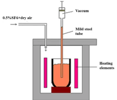
Commercial ingots of AZ91D were melted in mild steel crucibles using a vacuum filling process and gas protection in the form of a mixture of dry air and 0.5% SF6 to minimise the presence
of oxide films and inclusions during casting (see Figure 12). The melt was sucked up to the 1000 mm mild steel rods, which were cut into 170 mm long bars and re-melted in a Bridgman furnace device under protective gas (0.5% SF6 and dry air). The melt was maintained at 670°C
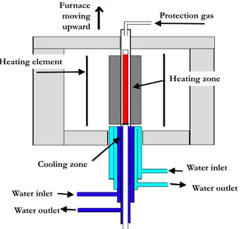
until fully melted at 30 minutes. The cooling rate of the specimen was controlled by the drawing rate of the furnace. Furnace pull rates in the range of 0.3-6mm/s were employed, depending on the desired scale of the microstructure, and resulted in microstructures with average SDAS values of 4.2-25 µm. A schematic depiction of the Bridgman furnace device used in the experiments is shown in Figure 13.
Figure 13. Schematic of the Bridgman furnace device used in the experiments.
2.3.3 Component-casting technique
The case study was a chainsaw engine crank (Figure 14). The components were produced using a cold-chamber HPDC machine (Buhler SC-D42 with 4000 kN locking force), and the protective gas was a mixture of 0.5% SO2 and dry air.
Figure 14. Configuration of the component.
The effects of process parameters and their interactions with component characteristics and performance were studied by investigating four HPDC parameters: first-phase injection speed (A in Table 4), the temperature difference between the two die halves through varying the temperature of the fixed half of the die (B), cooling time (C), and intensification pressure (D). Other process parameters were kept constant. The choice to omit second-phase injection speed was made due to the fact that the dwell time in the shot sleeve is in the order of 70 times longer than the duration of the second phase, resulting in temperature loss during the process being dominated by the shot chamber dwell time. The interfacial heat flux was in the order of 2 MW/m2 in the shot sleeve [103] and 6 MW/m2 in the die cavity [104] during filling, and so shot
sleeve dwell time is the dominant parameter as regards the temperature of the final part during processes. The minimum and maximum levels of HPDC parameters are given in Table 4. The interactions between these parameters were also studied. The DesignExpert™ software package (Stat-Ease) was used for the design of experiments (DOE) and, in order to have an effective experimental design, a quadratic response surface method was used with a D-optimal
Protection gas Furnace moving upward Heating zone Water inlet Water outlet Cooling zone Heating element Water outlet Water inlet
approach, with three replications and three runs performed in order to determine the lack of fit. Regression analysis and analysis of variance (ANOVA) were also employed.
Table 4. HPDC parameters and their minimum and maximum levels, together with the average of the reference-level parameters for the reference cast sample [105].
Symbol HPDC parameter Unit Min. level Max. level Ref. level A First-phase injection speed m/s 1.5 4.5 1.5
B Temperature of fixed half of the die °C 100 220 220
C Cooling time s 5 15 7
D Intensification pressure Bar 450 1100 824
2.3.4 Shot peening
Shot peening was performed by Husqvarna AB using their recommended peening procedure for improving the surface integrity of the components. Aluminium rods were used in the peening process.
2.3.5 Paint-bake cycle
Real paint was not applied, but the components went through paint-bake treatment. The paint application cycle involved a series of three-step processes, the first of which involved cleaning the components with water at a temperature of 40°C for 8 minutes. During the second step, the components were dried at 100°C for 20 minutes and cooled in the air. The third step was curing at 200°C for 30 minutes.
2.3.6 Tensile testing
Tensile bars were prepared according to ASTM B577 [106]. The geometry of the test specimen is shown in Figure 15. A ZWICK-ROLL™ Z100 laser extensometer was used to measure strain. Tensile tests were carried out between RT and 190°C at strain rates ranging from 10-4 to
10-1 1/s. In order to understand the relationship between microstructure and tensile
performance, a table of values was created, wherein the data from samples with different microstructures that had been tensile tested under various conditions was input, using the DesignExpert™ software. The minimum and maximum levels of the tensile test parameters are shown in Table 5. For each tensile test, at least four repetitions were considered to have statistical significance for the results. To facilitate effective optimisation, the number of data points was reduced using a specially devised MATLABTM code. Flow-stress curves, ultimate
tensile strength (Rm), stress at 0.2% offset strain (Rp0.2), and strain at which failure occurs (𝜀𝜀𝑓𝑓)
Figure 15. The geometry of the tensile test specimen [106]. Table 5. Minimum and maximum values of the parameters of the tensile tests.
Parameter Unit Min. level Max. level
Furnace pulling rate m/s 0.3 6
Temperature °C RT 190
Strain rate s-1 10-1 10-4
2.3.7 Component distortion measurements
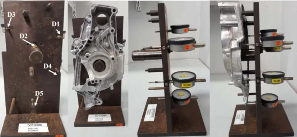
Distortion values were measured using the standard in-house quality-assurance tool (Figure 16), and compared to the dimensions of the actual HPDC components and the design component at the reference points D1-D5 (see Figure 17). The measured direction was along the normal vector of the surface, and the measurement yielded a (positive or negative) value that signified deviation from the zero plane.
Figure 16. The standard in-house quality-assurance tool used to measure distortion values. D1, D2, D3, D4 and D5 are the 5 reference points. [105].
![Figure 1. Mg-Al phase diagram [37].](https://thumb-eu.123doks.com/thumbv2/5dokorg/4625775.119476/17.892.221.747.629.1029/figure-mg-al-phase-diagram.webp)
![Figure 2. Solidification sequences of AZ91D alloys [45].](https://thumb-eu.123doks.com/thumbv2/5dokorg/4625775.119476/18.892.234.758.787.1069/figure-solidification-sequences-az-d-alloys.webp)
![Figure 5. Hot-chamber HPDC machine [46].](https://thumb-eu.123doks.com/thumbv2/5dokorg/4625775.119476/22.892.230.690.136.449/figure-hot-chamber-hpdc-machine.webp)
![Figure 8. Schematic illustration of a) the initial material with crystallographic directions c and a 1 ; , b) lenticular of tensile twin, c) compression twinning, d) double twinning [56]](https://thumb-eu.123doks.com/thumbv2/5dokorg/4625775.119476/25.892.156.655.116.662/schematic-illustration-material-crystallographic-directions-lenticular-compression-twinning.webp)

![Table 4. HPDC parameters and their minimum and maximum levels, together with the average of the reference-level parameters for the reference cast sample [105]](https://thumb-eu.123doks.com/thumbv2/5dokorg/4625775.119476/41.892.152.813.234.365/table-parameters-minimum-maximum-average-reference-parameters-reference.webp)
![Figure 19- Schematic of the component and points at which residual stress measurements were taken (R1-R3) [105]](https://thumb-eu.123doks.com/thumbv2/5dokorg/4625775.119476/44.892.301.664.839.1033/figure-schematic-component-points-residual-stress-measurements-taken.webp)
