OPTIMAL PIN FIN HEAT EXCHANGER SURFACE
Hamid Nabati
2008
Copyright © Hamid Nabati, 2008
ISSN 1651-9256
ISBN 978-91-85485-95-6
A
A
b
b
s
s
t
t
r
r
a
a
c
c
t
t
This research presents the results of numerical study of heat transfer and pressure drop in a
heat exchanger that is designed with different shape pin fins. The heat exchanger used for this
research consists of a rectangular duct fitted with different shape pin fins, and is heated from
the lower plate. The pin shape and the compact heat exchanger (CHE) configuration were
numerically studied to maximize the heat transfer and minimize the pressure drop across the
heat exchanger. A three dimensional finite volume based numerical model using FLUENT©
was used to analyze the heat transfer characteristics of various pin fin heat exchangers. The
simulation applied to estimate the heat transfer coefficient and pressure drop for a wide range
of Reynolds numbers with different pin fins. Circular pin configuration variations included
changes in pin spacing, axial pitch and pin height ratio. Rectangular and drop-shaped pin
variations also included changes in length and aspect ratio. Correlations for Nusselt number
and friction factor were developed. The optimum drop shaped pin array was shown to match
the heat transfer rates obtained by the optimum circular pin configuration while incurring less
than one third the specific fluid friction power losses. The data and conclusions of this study
can be applied to the optimization of different heat exchangers which are used in industry,
especially oil cooler in power transformers which are currently working with low cooling
efficiency. It can also be used in the design of electronic components, turbine blade cooling or
in other high heat flux dissipation applications requiring a low-profile, high area-density
based micro-heat exchanger design. This study also shows that numerical models backed with
experimental analysis can reduce both the time and money required to create and evaluate
engineering concepts, especially those that deal with fluid flow and heat transfer.
In the following chapters, first the problems which are encountered by power transformer
suppliers are described. Then pin fin technology is studied with more details as a novel
solution to the oil cooling problem. Some studies on behavior of power transformer coolers
are also conducted to make their problems more clear. Available experimental data in the Iran
Transfo company have been used for validation of these studies. They are presented as
separated papers at the end of thesis. Finally the results of pin fin studies are presented and
horizontal continuous casting (HCC) is explained as a manufacturing method for pin fins
production. A separate paper which is based on experimental study on HCC is also included
at the end of thesis.
S
S
a
a
m
m
m
m
a
a
n
n
f
f
a
a
t
t
t
t
n
n
i
i
n
n
g
g
Forskningen presenterad är ett resultat av en numerisk studie av värmeöverföring och
tryckfall i en värmeväxlare designad med olika former av Kylflänsar. Värmeväxlaren består
av ett rektangulärt kanal utrustat med olika former av Kylflänsar och är uppvärmd underifrån.
Kylflänsar forma och den kompakta värmeväxlarens utformning är studerade numeriskt för att
maximera värmeöverföringen och minimera tryckfallet över värmeväxlaren.
En tredimensionell finit volym baserad på en numerisk modell i FLUENT© användes för att
analysera värmeöverföringsegenskaper för olika Kylflänsar konfigurationer. Genom
simuleringar uppskattades värmegenomgångstalet och tryckfallet för olika Reynolds tal och
Kylflänsar konfigureringar. Cirkulära Kylflänsar konfigurationer inkluderar variation av
avstånd mellan Kylflänsar, och förhållandet mellan axiellt avstånd och höjd. Rektangulära och
droppformade Kylflänsar inkluderade även variation för längd och aspekt förhållande.
Korrelation mellan Nusselts tal och friktionsfaktor utvecklades. Optimal matris för hur
droppformade Kylflänsar placerades visades överensstämma med optimal överföring för
cirkulära Kylflänsar men bara med en tredjedel av friktionsförlusterna för fluiden. Data och
slutsatser från studien kan användas inom för optimering av värmeväxlare använda i industrin,
speciellt oljekylda högspänningstransformatorer som har låg effektivitet i kylningen.
Resultaten kan även användas inom design av elektronikkomponenter, kylning av turbinblad
eller andra komponenter med högt värmeflöde där låg profil, och stor ytdensitet behövs.
Studien visar att kombinationen av numeriska modeller som valideras genom experiment kan
reducera både tid och kostnad vid utveckling och utvärdering av ingenjörsverktyg, speciellt
inom fluidmekanik och värmeöverföring.
I följande kapitel beskrivs först problem som identifierats av tillverkare av
högspänningstransformatorer. Kylflänsar studeras i detalj som en ny lösning till de
identifierade problemen med oljekylning. Några studier har genomförts för att ytterligare
belysa problemen kring högspänningstransformatorers kylning. Tillgängliga data från Iran
Transfo company har använts för validering av resultat från studierna. Studierna presenteras
som separata artiklar i slutet av avhandlingen. Avslutningsvis presenteras resultat från
studierna av Kylflänsar och en horisontell kontinuerlig gjutprocess (HCC) för tillverkning av
Kylflänsar. HCC-studien presenteras som en separat artikel inkluderad sist i avhandlingen.
A
A
c
c
k
k
n
n
o
o
w
w
l
l
e
e
d
d
g
g
e
e
m
m
e
e
n
n
t
t
s
s
This thesis has been carried out at the School of Sustainable Development of Society and
Technology, Mälardalen University, Västerås, Sweden as licentiate thesis.
I would like to express my most sincere gratitude to my academic supervisor, Professor Jafar
Mahmoudi who encouraged me to start this work and patiently supported me in many
different aspects throughout this work.
Also my special thanks go to Erik Dahlquist for his useful lectures and many hours of
discussions on optimization, reviewing and ideas in articles and research methodologies.
I also wish to thank my wife Narges for her patience and support and also my parents for
continuously encouraging me. My lovely kid, Armita has been the light for my way.
Special thanks to my friends and colleagues at MdH and the department of energy technology
at KTH who have helped and been a supportive on both the technical and the social level.
And finally, I would like to thanks Tommy Larsson and Örjan Danielsson for their efforts in
reviewing my thesis and putting valuable comments on it
L
L
i
i
s
s
t
t
o
o
f
f
P
P
u
u
b
b
l
l
i
i
c
c
a
a
t
t
i
i
o
o
n
n
s
s
This thesis is based on the following five papers and technical report:
Papers
• Nabati H., Mahmoudi J., "Numerical Study of Thermal Performance of Different Pin-Fin
Morphologies", 46th Conference on Simulation and Modeling (SIMS 2005), Trondheim,
Norway, 2005.
• Nabati H., Mahmoudi J., "Optimal Pin Fin Heat Exchanger Surface for Pulp and Paper
Industry", the Fifth International IMACS Symposium on Mathematical Modeling(5th
MATHMOD), February 8 – 10, Vienna University of Technology, Vienna, Austria, 2006.
• Nabati H., Mahmoudi J., "Numerical Modeling of a Plane Radiator Used in a Power
Transformer Cooling System", To be published in the Journal of Applied Energy.
• Nabati H., Mahmoudi J., "Simulation of Power Transformer’ Cooling System in ONAN
State", To be published in the Journal of Applied Energy.
• Mahmoudi J., Nabati H., "An Experimental Study on Productivity and Quality
Improvement of Horizontal Continuous Casting Process ", International Journal of Green
Energy, Volume 3, Number 2, PP. 185-189, April-June 2006.
Report
• Hamid Nabati and Jafar Mahmoudi, "Numerical Study of Thermal Performance of
Different Pin Fin Morphologies with Air Impingement through CFD Modeling”, MdH/IST
(2005).
N
N
o
o
m
m
e
e
n
n
c
c
l
l
a
a
t
t
u
u
r
r
e
e
Latin Letters
A
surface area [m
2]
C
Pspecific heat capacity [j/kg.K]
D
circular and drop-shaped fin diameter, Rectangular fin width [m]
D
hhydraulic diameter [m]
f
friction coefficient (Total pressure loss coefficient)
h
convective heat transfer coefficient [W/m
2.K]
H
pin fin height [m]
k
turbulent kinetic energy [m
2/s
2]
m&
mass flow rate [kg/s]
Nu
DNusselt number based on Dh
P
pressure [pa]
Pr
Prandtl number
Q,q rate of heat transfer [W]
R
thermal resistance [K/W]
Re
DReynolds number based on D
T
temperature [K]
T
Hheat source temperature [K]
u,U, U velocity [m/s]
Greek Letters
DP
pressure drop [pa]
Θ
non-dimensional temperature
α
thermal diffusivity [m
2/s]
θ
means temperature [K]
ε
turbulent dissipation rate [m
2/s
3]
ρ
density [kg/m
3]
ε
ffin effectiveness
η
ffin efficiency
λ
thermal conductivity [W/m.K]
µ
molecular viscosity [Pa.s]
µ
teddy viscosity [Pa.s]
T
T
a
a
b
b
l
l
e
e
o
o
f
f
C
C
o
o
n
n
t
t
e
e
n
n
t
t
s
s
CHAPTER 1 - INTRODUCTION ... 7 1.1 Motivations ... 10 1.2 Research approach ... 11 1.3 Literature review ... 11CHAPTER 2 - PROBLEM DESCRIPTION ... 20
2.1 Objectives ... 20
2.2 Heat exchangers characteristics ... 20
2.3 The scope of this work ... 21
CHAPTER 3 - GOVERNING EQUATIONS ... 23
3.1 Basic fin theory and definitions ... 23
3.2 The instantaneous equations ... 28
CHAPTER 4 - NUMERICAL SOLUTION PROCEDURE ... 31
4.1 Model description ... 31
4.2 Pin-Fins' geometry ... 34
4.3 Boundary conditions ... 37
4.4 Simulations ... 39
CHAPTER 5 - RESULTS AND DISCUSSION ... 44
5.1 Nusselt number ... 44
5.2 Friction factor ... 45
5.3 Heat transfer ... 48
CHAPTER 6 - CONCLUSION REMARKS... 57
6.1 Optimization ... 57
6.2 Horizontal continuous casting as a production method ... 58
6.3 Future work ... 60
REFERENCES ... 62
C
C
h
h
a
a
p
p
t
t
e
e
r
r
1
1
1
Introduction
Transformers are widely used in the industry, especially in power distribution networks.
They are most valuable assets in power systems and it appears worthwhile to pay special
attention to this key component to ensure stability in power systems. Iran Transfo Corporation
is one of the leading Iranian manufacturers of single and three phase oil immersed distribution
transformers since 1966 that produces distribution transformer with capacity of 12000 MVA
and power rating up to 5000 kVA and 36 kV. The energy losses in these power transformers
are proportional to the load. These losses are transformed into heat which causes a
temperature rise that can reach high levels and affects negatively the transformer performance
which means an operational load and useful life reduction. The heat dissipation by means of
natural convection through its own surface is enough in small transformers. This heat
dissipation medium is not enough for transformer of average and high power, which require
more elaborated methods of cooling and generated heat must be removed effectively [50].
In the Iran Transfo power transformers, the cooling is provided through circulation of oil
between ducts in the active parts and heat exchangers outside the transformer tank. The oil
circulation is due to free convection or combined free and forced convection. In power
transformers design, it is in the interest of Iran Transfo to minimize the size of heat
exchangers and internal cooling ducts. In the literature, few studies have been made on the
heat transfer and the fluid flow outside the transformer. Most studies have focused on inside a
power transformer. For example recently Mufuta and Van Den Bulck [51] studied the case of
a winding disc-type transformer and they showed the influence of Re.Gr
−1/2on the flow
structure and gave some correlations to calculate the heat transfer inside this kind of
transformer. Heat transfer inside the channels and thermal behavior of the flow in a pipe with
different boundary conditions are investigated widely in heat transfer texts, but no special
paper with focus on the radiator were found in the literature. One novel idea to overcome
above transformer power loss problems is using the widthwise pin fins between radiators. A
typical transformer which is assembled in Iran Transfo Company is shown in the figure 1.1.
To achieve better performance, conventionally, fins are added to plain tubes resulting in large
external surface area and high heat transfer performance and smaller dimensions. Figure 1.2
shows some kind of usual fins used in different heat exchangers.
Figure 1.1 A typical power transformer equipped with auxiliary fans [52]
Figure 1.2 Some of the many varieties of finned tubes [1].
Several big and small companies are involved in producing and manufacturing such kinds of
tubes. As mentioned above, one of the most recent interesting methods in enhanced heat
exchanger design is in pin-fin technology. Pin fin is suitable for numerous applications
including processes using liquids and gasses, oil, diesel, high-pressure water and steam. Pin
Fin can be manufactured using a variety of base tube materials such as copper, brass,
copper/nickel, aluminum/brass, carbon steel and stainless steel. In recent years, this
technology has become one of the major techniques in heat sinks design for electronics
cooling. Because of the highly conductive nature of copper, the copper heat sinks are getting
more and more favorable. Figure 1.3 shows one of the Pin-Fin heat sinks which is used in
computers processor cooling.
Pin-Fin technology has shown its excellent characteristic in heat transfer in electronics
cooling and it seems that its time to use this technology in conventional heat exchangers used
in industrial application. The usage of this technology in tubes will overcome the problems
that other heat transfer enhancement tubes could not solved for long time, i. e. large pressure
loss and low total heat transfer efficiency. Its unique finned structure greatly increases
heat-exchanging area both inside and outside the tube with dramatically reduced thickness of
boundary layers. Some of the features are presented below [4]:
1. Convection heat exchanging coefficient for single-phase fluid is 2.5 to 6 times higher than
that of the plane tube.
2. Boiling heat transfer coefficient is 2 to 5 times higher than that of the plane tube.
3. Condensing heat transfer coefficient is 3 to 6 times higher than that of the plane tube.
4. Unique self-cleaning feature greatly reduces maintenance cost of heat exchangers.
Recently, few companies have started to produce Pin-fin tubes and use it in heat exchangers'
applications. For example, GREE THERMO-TECH CO. in China produces the pin-fin tubes
and recommends them for using in different types of heat exchangers (Figure 1.4). However,
no technical data are available in the company's home page (a possible explanation is that the
pin fin technology is becoming attractive and leading companies are not interested in
releasing the technical data). Another company which uses this technology in its products is
the Raypak company in the USA. The pin-fin tubes are widely used in the company's
products, especially in the boilers. Therefore, it seems that the study of pin-fin's applicability
in heat exchangers (like oil cooler in power transformers) and working on the different
technical aspects of it could give attractive solutions in heat exchangers' field and produce
more efficient and compact heat exchangers.
Fins morphology has a great effect in heat transfer characteristics and manufacturing. Most of
the used pin-fin has regular geometry such as cylindrical, rectangular and conical or semi
conical.
1.1 Motivations
Lately compact heat exchangers (CHE) have been subject of extensive research, because of
their importance in a wide variety of engineering applications. Fins are playing a vital role in
such equipments to enhance their performance.
As radiators used in power transformers are typical heat exchangers, that their performance is
not sufficient to solve the overload conditions that take place in the hot seasons, it seems
attractive to use the pin fin technology inside or outside of these heat exchangers to enhance
their efficiency. The following studies could be carried out in order to improve heat transfer
characteristic in radiators: change of oil flowing passage profile, change of radiators
dimensions and using the widthwise pin fins between radiators. All of these proposals need a
deep understanding of pin fins behaviour and their heat transfer characteristic.
Also large numbers of different heat exchangers are used in vital industries like power plants,
power transformers and pulp and paper mills, especially in their steam boiler which is the
heart of plant. The pulp and paper industry consumes a noticeable portion of all the primary
energy consumed in the industrial countries manufacturing. The efficiency of the air-side heat
transfer is a primary consideration when determining the best heat exchanger for a particular
application. Surface enhancement using pin fins could be a promising method to overcome
the described problem as well as maintenance efforts.
Commonly, pin-fin arrays are made up of a group of solid pins that span the end walls of an
internal flow passage or duct. The array is usually configured with cylindrical pins in either a
staggered or in-line arrangement with the coolant flowing perpendicular to the pin axes. Pins
can either be long with H/D greater than about 10, or short with H/D on the order of unity.
Alternatively, these pin fin arrays could be used to cool integrated circuit chips in electronic
equipment. These components could be mounted directly on top of a microscale pin-fin array
cooled by forced convection.
As yet no detailed study on the performance of such finned tubes has been carried out; the
present research involves a numerical investigation of heat transfer characteristic of different
shape finned tubes. The goal of this research is to develop strategies for finding the optimal
pin-fin geometry to use in external finned tubes. To reach this goal, a computational modeling
of heat transfer phenomena has been done using commercial CFD software and through it the
convective and conductive heat transfers in the model has been examined. As pressure loss is
one of the important parameters in the systems, in addition to the thermal study, effect of air
flow bypass characteristics and flow field has been investigated too.
1.2 Research approach
Hypothesis of this thesis:
"Pin fin geometry highly affects the different heat exchangers efficiency. Heat exchangers
with drop shaped pin fins can obtain higher heat transfer characteristics with lower pressure
drop."
To test this hypothesis the following tasks have been performed. A numerical study using
FLUENT© has been conducted to select the optimum pin shape considering maximum heat
transfer and minimum pressure drop across the heat exchanger. A numerical simulation has
been investigated using three dimensional models of a compact heat exchanger consisting of a
rectangular duct with inline arrays of three different shapes pin fins in a cross flow of air. The
heat transfer and associated pressure drop behavior are characterized. Different parameters are
investigated and an optimum geometric configuration together with a pin shape is selected
based on the overall heat exchanger performance. Finally a comparison between pressure drop
and heat transfer is carried out.
1.3 Literature review
This section presents a brief look at the research that has been conducted prior to the
writing of this report. This literature review includes a discussion of current state-of-the-art
issues and optimization techniques involved with thermal management in compact heat
exchangers and e-cooling.
One of the most referenced works is that of C. L. Chapman and Seri Lee paper [5]. They
carried out comparative thermal tests using aluminum heat sinks made with extruded fin,
cross-cut rectangular pins and elliptical shaped pins in low air flow environments. They
developed an elliptical pin fin heat sink with specific design parameters, maintaining large
exposed surface area for heat transfer and minimizing vortex flow by incorporating an airfoil
design. The approach taken in the paper was to compare this elliptical shaped heat sink with a
amount of flow bypass terms to measure the effects of different thermal conductivity, flow
characteristics and pressure drop on heat sink performance. Figures 1.5 and 1.6 show the
schematic diagram of different heat sinks that they used and their experimental test set-up.
They found that there was 40% more air flowing through the rectangular pin design, yet the
thermal resistances were virtually equal and the elliptical pin fin enhanced the heat transfer.
Figure 1.5 Schematic diagrams of different heat sinks for tests [5]
These results were in correlation with the basis of the elliptical pin fin design considerations,
i.e. vortex flow is reduced and boundary layer effects are eliminated. Also surprisingly they
found that extruded straight design performed significantly better than either of the two other
designs over the flow range which they examined there.
The other work which is studied for current research is a master thesis [11]. This thesis
presents the results of a combined numerical and experimental study of heat transfer and
pressure drop behavior in a CHE designed with drop-shaped pin fins (Figure 1.7). A
numerical study using ANSYS was first conducted to select the optimum pin shape and
configuration for the CHE. This was followed by an experimental study to validate the
numerical model.
The results indicate that the drop shaped pin fins yield a considerable improvement in heat
transfer compared to circular pin fins for the same pressure drop characteristics. This
improvement is mainly due to the increased wetted surface area of the drop pins, and the
delay in the flow separation as it passes the more streamlined drop shaped pin fins.
Figure 1.7 Staggered pin-fin array[11]
One of the most recent published papers in the pin-fin field is B. Moshfegh and R. Nyierdy'
paper [12]. Although their paper discusses various levels of numerical modeling of turbulent
flow that are relevant to electronic cooling, their guidelines are very useful for similar works.
The model under consideration is a 3-D model of circular pin fin heat sinks in bypass flow
conditions (Figure 1.9).
Three different inlet velocities have been considered corresponding to a channel Re = 5000 to
14500. Results are presented for the base plate temperature, the pressure drop, as well as the
influence of flow bypass, and the leakage from the interfin region to the bypass regions of the
domain. The Gambit grid generation package is used to generate the 3-D unstructured grid.
Due to symmetry conditions in the span-wise direction, only half of the channel has been
considered. Two grids of different density were used for computation of the test cases. The
coarse grid has 360 333 hexahedral cells. The mesh close to the pins is finer with a mesh
distribution of 108×52×35.
(a)
(b)
Figure 1.8 (a) Computational grid (b) Sample velocity profile for drop shaped pin fins
[11]
The Gambit grid generation package is used to generate the 3-D unstructured grid. Due to
symmetry conditions in the span-wise direction, only half of the channel has been considered.
Two grids of different density were used for computation of the test cases. The coarse grid has
360 333 hexahedral cells. The mesh close to the pins is finer with a mesh distribution of
108×52×35. The mesh is non-conformal at the interface between fine and coarse region
(Figure 1.10). The grid distribution for the coarse mesh has been effectively controlled by
clustering the mesh towards the walls and edges in such a way that the wall function can be
applied properly, i.e. the first numerical point was always located at y
+>15(y
+is a
non-dimensional wall distance for a wall-bounded flow). The finer grid ensured that the wall
nearest y
+is kept close to one near the walls and edges. The finer grid consists of 1 710 027
cells and is used for computation with the k-ω.
Figure 1.10 Non-conformal (left) and conformal (right) grid structures are used for
coarse and fine mesh respectively [12].
The result shows that choosing the right turbulence model and near-wall treatments have a
great influence on the heat transfer coefficient and the pressure drop. Figure 1.11 shows some
of their results.
Because of the various industry applications for finned tubes, there are many different fields
of research. The research papers that are referred frequently in literatures are concerned with
correlations (Kröger, 1986 [13]), convection (Hahne and Zhu, 1994[14]) and conduction
(Ranganayakulu et al., 1999 [15]).
To compare the performance of different types of finned-tubes, (Kröger, 1986 [13]) derived a
method to present the heat transfer and pressure drop characteristics of finned-tube bundles.
Another correlation for finned-tubes was empirically derived by Idem et al. (1987) [16]. It
could be used to predict the performance characteristics of untested, geometrically similar
heat exchangers.
The purpose of the extended surface heat exchanger is to increase the heat transfer. There are
several existing heat exchangers that already do this and it is the aim of this section to look at
a couple of these heat exchangers. The literature study was limited to roughened surfaces,
finned tubes, offset strip fins, pin fins and micro fins:
• Roughened Surfaces
Heat transfer enhancement takes place through roughened surfaces by promoting turbulence
[19]. In an article by Firth and Meyer [20] the ribs of four different surfaces were evenly
spaced and the heat transfer coefficients and friction factors were compared. Zhang et al. [21]
used a parallel plate channel with staggered ribs to study the effects of compound turbulators
on friction factors and heat transfer coefficients.
Results of the above articles showed that any advancement in heat transfer was counter
balanced by the pressure drop. Several different configurations were studied to find the design
with the least pressure drop. Finding the best rib angle was the object of a paper by Han et al.
[22]. It was found that ribs at a 45° angle of attack had better heat transfer characteristics than
one with a 90° angle of attack for a given pressure drop. The effects of conduction were
included in a study by Webb and Ramadhyani [23]. While investigating the heat transfer and
friction properties for a parallel plate channel with staggered ribs, it was found that
conduction in the channel walls contributed to the enhanced heat transfer.
An internal finned tube is a round or rectangle tube with continuous fins inside the tube to
enhance heat transfer. An advantage of internally finned tubes is that it is an easy and efficient
way to enhance internal convection [24]. The following articles derive equations for the heat
transfer coefficients and friction factors of these configurations for laminar and turbulent
flow. Several papers analysed laminar flow in internally finned tubes.
In Soliman et al.’s [25] paper the distribution of fin temperature, fluid temperature and local
heat flux with uniform outside wall temperature was numerically derived for finned and
unfinned configurations. The results showed that the distribution of heat flux was dependent
on the amount of fins and fin height and that the finned tube had better heat transfer
characteristics surface that a smooth tube. Renzoni and Prakash [26] derived flow and heat
transfer characteristics for developing flow in the entrance region of an internally finned heat
exchanger. The theoretical results showed the pressure drop and Nusselt number for the
entrance regions as well as estimates for the hydrodynamic and thermal entrance lengths.
Other articles about laminar flow in internally finned tubes were done by Rustum and
Soliman [27], [28] and both were about mixed convection. Experimental results for the
pressure drop and heat transfer characteristics for laminar flow were showed in their first
paper (1988). The results showed that the free convection had a strong influence on heat
transfer and approached the forced-convection predictions as the Rayleigh number decreased.
The numerical analysis was based on the modified Grashof number, Prandtl number, number
of fins and relative fin height. From the analysis, the secondary flow, axial velocity and
temperature distribution, wall heat flux, friction factor and average Nusselt number were
derived. These results were compared with experimental results and good correlation was
found. Other conclusions were that the onset of free convective effects was delayed and that
the enhancement of friction factor and Nusselt number was suppressed.
In internally finned tubes the flow can also be turbulent. The turbulent flow was analysed by
Patankar et al. [29], Webb and Scott [30], Kim and Webb [31]. The results found were
compared with available experimental data.
Patankar et al. [29] used a mixing length model for analysing an internally finned tube. For
the analysis the Nusselt number and friction factor were derived. The results also showed that
the fins were a better transfer surface than the tube wall.
An internally finned tube was analysed for three design cases by Webb and Scott [30]. The
design cases were:
· Reduced tube material volume for equal pumping power and heat transfer.
· Increased heat transfer for equal pumping power and length of heat exchanger tubing.
· Reduced pumping power for equal heat transfer and length of heat exchanger tubing.
The results showed that although material savings were found using axial internal fins, much
better savings were obtained when the fins had a helix angle (twisted).
A comparison with the empirical Carnavos correlations was made in the analytical model
used by Kim and Webb [31] in their article about axial internal fin tubes. The friction factor
and heat transfer equations were derived and predicted the Carnavos friction data within 10%
and the Carnavos heat transfer data within 15% accuracy.
• Finned Tubes
A finned tube heat exchanger consists of a tube with fins on the outer side of the tube.
Finned-tube heat exchangers are used in many applications such as industrial boilers, commercial air
furnaces and water heaters [16]. Because of the various industrial applications for finned
tubes, there are many different fields of research.
• Offset Strip Fins
Offset strip fins heat exchangers are used as evaporators in the refrigeration and air
conditioning industry [32]. The fins cause a recirculating flow between two successive fins.
Enhanced heat transfer is obtained due to the fins preventing the flow from becoming fully
developed and the restarting of the boundary layer produces higher heat transfer [33].
• Pin Fins
This kind of fins is introduced at the beginning of this chapter.
• Micro Fins
A typical micro fin tube has tiny fins of triangular cross-section at a helix angle of between 8°
- 30°. The diameters of the tube varied between 6.35 and 15.9 mm [34]. Micro fin heat
exchangers are used in the refrigeration, automotive and process industries because it
enhances heat transfer by two to three times that of a plain tube [35]. Micro fin tubes are
popular because a large heat transfer enhancement can be achieved relative to the increase in
pressure drop. Mainly evaporation and condensation are investigated by researchers to find an
optimal design for a specific application.
Evaporation was investigated by Kuo and Wang [36] and compared to a smooth tube. The
results showed that the heat transfer enhancement ratio was approximately 2.2.
Other characteristics of micro fins that are investigated are heat transfer coefficients and the
size effects of micro fins. Flow boiling heat transfer coefficients were experimentally found
for R-134a in a micro fin tube. When the heat flux increased, the heat transfer coefficient
increased as well because of the increase in nucleate boiling [37].
One article found dealt with the size effects on thermal conductivity of channel and fin walls.
Chou et al. [38] reported that size effects reduced the thermal conductivity and therefore the
heat transfer rate as well. Choking in micro fins, heat transfer enhancement ratio and plate
thickness optimization were investigated. The paper concluded by stating that in the micro
scale the shape and size effects should be taken into account in the design of heat exchangers.
• Other enhancement
The above articles represent only a part of the different enhanced heat exchanger
configurations. For example twisted tape inserts can be placed inside tubes [39] to increase
the heat transfer. Other types of enhanced heat exchanger are the plate- fin arrangement and
the louvered fin compact heat exchanger [40-43].
A popular fin pattern for heat transfer enhancement is the wavy fin configuration [44]. In this
paper, correlations for the airside performance of a wavy fin heat exchanger were derived
using samples. A generalized heat transfer coefficient and friction factor were proposed that
were within 15% of the sample data.
This study shows that the subject of the proposed research is quite extensive and needs a
comprehensive study on different subjects.
Based on these studies some optimal configuration will be proposed and using numerical
procedures, the best one will be highlighted. Finally experiments will be used to verify the
numerical results. This report focuses on numerical aspects which are involved in the current
research.
C
C
h
h
a
a
p
p
t
t
e
e
r
r
2
2
2
Problem Description
2.1 Objectives
The final goal is to develop CFD-methods for realistic prediction of the overall heat transfer
coefficient in a passage containing in-line array of pin fins, in order to improve the heat
transfer efficiency. Therefore, generic flow cases with three different fin geometries that have
the typical flow-heat transfer characteristics are investigated. Figure 2.1 shows a typical
passage including an in-line eight rectangular fin array.
The focus of this work is on the investigation of the effects of fin morphology in prediction of
the flow and heat transfer in a typical heat exchanger passage. Also the study of the
underlying physics of the flow-heat transfer processes in these cases is included.
Figure 2.1 Typical studied passage including eight rectangular fins with in-line
arrangement
2.2 Heat exchangers characteristics
A heat exchanger is a complex device that provides the transfer of thermal energy between
two or more fluids at deferent temperatures. Heat exchangers are used, either individually or
as components of larger thermal systems, in a wide variety of industrial, commercial, and
household applications, e.g. refrigeration, ventilating and air-conditioning systems, power
generation, process like pulp and paper mills, manufacturing and space industries, as well as
in environmental engineering. Although a wide variety of heat exchangers exists in the
market, the present dissertation will concentrate in the commonly used compact heat
exchanger. A typical single-row fin-tube compact heat exchanger is shown schematically in
Figure 2.2. The complexity of these systems stems from their geometrical configuration, the
physical phenomena present in the transfer of heat, and the large number of variables involved
in their operation. As a consequence of such complexity, no analytical solutions entirely based
on a first-principles approach are available; most calculations are based on empirical
information from the manufacturers of these equipments.
Since heat exchanger performance very often is a key factor in the overall thermal system
design, constant improvements in their modeling and simulation are definitely needed to
increase the accuracy of their predictions and, consequently, to improve the reliability and
efficiency of thermal systems for the specific application. This thesis is especially concerned
with the enhancement in the steady state performance of pin finned-tube compact heat
exchangers based on the concepts raised from new e-cooling technology.
Figure 2.2 Single-row fin-tube heat exchanger
2.3 The scope of this work
The scope of this work has been limited to the flow and heat transfer in a rectangular duct
fitted with three different shape pin fins. Understanding these kinds of pin fins which are used
widely in industry is believed to give a rich contribution to elucidation of the phenomena in
normal and compact heat exchangers used in different application. It was, therefore, chosen to
investigate the heat transfer and pressure drop characteristics in a channel containing three
basic pin fins, namely rectangular fins, circular fins, and drop shaped fins at both low and
high Reynolds numbers. There are a number of such studies available in the literature
including the experimental studies of VanFossen [45] which investigated the heat transfer
coefficients for staggered arrays of short pin fins, Metzger et al [46] who studied the
developing heat transfer in rectangular ducts with staggered arrays of short pin fins, Chyu and
Goldstein [47] who used the mass transfer analogy to study the influence of an array of
wall-mounted cylinders. Most of these studies investigated the cylindrical shaped pin fins. There
are few papers that studied the effect of different shape pin fins.
It is therefore a challenge and of great interest to simulate such a flow with different pin fin
morphologies using CFD-tools that are intended to be used for industrial applications. Figure
2.3 illustrates that prior to a CFD-analysis, several parameters should be considered and some
decisions should be made. The study of fluid flow and heat transfer around pin fins in a
rectangular channel having three dimensional complex fluid flows contributes also to the
understanding of the flow and heat transfer mechanisms in industrial applications. The
objectives of this work are to explore the complex flow in this kind of channel and to evaluate
and improve the methods for accurate prediction of flow and heat transfer characteristics in
such generic cases for final use in more complex engineering applications.
Figure 2.3 parameters to be considered and decisions to be taken and their inter-action
prior to a CFD analysis
Difference Scheme
- 1
storder
- 2
ndorder
- 3rdorder
Turbulence Model
- Reynolds-Averaged Approach
- Large Eddy Simulation (LES)
- Reynolds (Ensemble) Averaging
- Standard k-epsilon Model
- RNG k-epsilon Model
- Realizable k-epsilon Model
- Reynolds Stress Model
- Spalart-Allmaras Model
Grid
- Mesh density
- y
+- Fluid + solid?
Physics
- Isotheral
- Thermal
- Conjugate heat transfer
Boundary Conditions
- Empirical
- Simulated
- Mapped
C
C
h
h
a
a
p
p
t
t
e
e
r
r
3
3
3
Governing Equations
3.1 Basic fin theory and definitions
Generally, when the convective heat transfer coefficient is small, (a condition commonly
encountered when the surrounding fluid is a gas) the rate of heat transfer can be increased
appreciably by installing extended surface or fin on the surface. The extended surface are
classified as straight fins, annular or circumferential fins and spines or pin fins as shown in
figure 3-1[9].
Figure 3.1 Different types of extended surfaces [9]
Here we will focus on Pin-Fins which provide heat transfer augmentation via the repeated
growth of laminar boundary layers, followed by dissipation in the wake regions. To show the
essential features of fin behavior and introducing the basic definitions, we start with the
analysis of a straight fin protruding from a wall. Figure 3-2 shows such fin with one
dimensional characteristic.
The temperature of the fin’s root is kept constant at T
0. The fin body is cooled (or heated) by
ambient air, its temperature is assumed to be T
∞.The convective heat transfer coefficient,
his supposed to be uniform along the whole length of the fin. Though this assumption is not
very accurate, we use it to formulate the fin behavior.
Figure 3.2 Analysis of one-dimensional fin [1]
The temperature distribution along the fin is necessary to obtain its associated heat transfer.
Considering the negligible radiation heat transfer from fin surface and one dimensional
conduction through the fin, the energy balance on a thin differential element is performed as
following:
0
)
).(
.
.(
.
.
+
+
−
=
−
∞ + + x x x x xT
T
x
P
h
dx
dT
kA
dx
dT
kA
δ
δ δ(3.1)
Rearranging the equation 3.1 yields:
)
(
)
(
2 2 ∞ ∞=
−
−
T
T
kA
P
h
dx
T
T
d
(3.2)
Boundary conditions for this equation are:
(
)
L x L L x o xT
T
A
h
dx
T
T
d
kA
T
T
T
T
= ∞ = ∞ ∞ = ∞−
=
−
−
−
=
−
)
.(
.
)
(
0(3.3)
For the case of negligible heat transfer at the fin tip( like an insulated tip), then the Boundary
conditions can be considered as:
(
)
0
)
(
0=
−
−
−
=
−
= ∞ ∞ = ∞ L x o xdx
T
T
d
kA
T
T
T
T
(3.4)
To work with dimensionless parameters, (as it´s usual in fin literatures), we use following
substitutions:
mL
kA
PL
h
L
x
T
T
T
T
o=
=
−
−
=
Θ
∞ ∞ 2ξ
(3.5)
We put equation (3.3) in these terms by multiplying it by L
2/(T
o-T
∞). The result is:
Θ
=
Θ
.
)
(
2 2 2mL
d
d
ξ
(3.6)
This equation is satisfied by
.
(mL)ξe
C
±=
Θ
which can be written in the following form to
yield the general solution of equation (3.6):
ξ ξ mL mL
e
C
e
C
+
−=
Θ
1.
2.
(3.7)
C
1and C
2will be calculated according to boundary conditions and they are different in
different cases.
It is obvious that the mL is a useful parameter in the analysis and design of fins. If equation
3.5 is rearranged:
resistance
external
gross
direction
x
in
resisance
internal
)
)
.(
1
(
)
(
)
(
2=
=
PL
h
kA
L
ml
(3.8)
When
(mL
)
2is big,
Θ
ξ=1→
0
and tip convection can be neglected. When it is small, the
temperature drop along the axis of the fin becomes small.
One of the most important design variables for a fin is the rate at which it removes (or
delivers) heat the wall. To calculate this, the Fourier’s law for the heat flow into the base of
the fin is written
:0
)
(
= ∞−
−
=
xdx
T
T
d
kA
Q
(3.9)
Two other basic measures of fin performance, which are particularly useful in a fin design, are
fin efficiency, η
fand fin effectiveness, ε
f[9]:
0
T
T
at
fin were
entire
the
if
ed
transferr
be
would
heat that
fin
a
by
ferred
heat trans
actual
=
=
fη
(3.10)
fin
he
without t
wall
the
from
flux
heat
fin
with the
wall
the
from
flux
heat
=
fε
(3.11)
Though η
fprovides some useful information on fin designing, there is not a particular η
fwhich represents the best design. On the other hand, it seems that the effectiveness should be
as high as possible which is always achievable by extending the length of the fin. But this
solution is a loosing proposition. For a reasonable design, ε
fshould be as big as possible and
generally, when ε
f≤ 2, there is no use for fins. The fin effectiveness can be increased by the
following considerations:
1- Selection of high conductive materials (such as copper and aluminum, however,
aluminum is more usual, because of its lower price and weight).
2- Increase in the circumference to section area ratio. This is the reason for using thin
fins in engineering applications.
3- Using fins in cases that the convection heat transfer coefficient (h) is low. Fins are
always used in the gas section, where h is less.
Thus fin design is still an open-ended subject of optimizing, subjected to many factors.
Lienhard and Lienhard [1] have summarized some of them:
“ 1- The weight of material added by the fin. This might be a cost factor or it might be an
important consideration in its own right.
2- The possible dependence of
h
on (T - T
∞), flow velocity past the fin, or other influences.
3- The influence of the fin (or fins) on the heat transfer coefficient, h, as the fluid moves
around it (or them).
4- The geometric configuration of the channel that the fin lies in. the cost and complexity of
manufacturing fins.
5- The pressure drop introduced by the fins”.
The last parameter that we are dealing with in this section is fin thermal resistance which is
defined as the ratio of a temperature difference (as driving potential) to the corresponding heat
transfer rate. This means that the fin acts as a thermal resistance between the root and the
surrounding ambient. For a straight fin with negligible heat transfer at its tip, we have [1]:
fin t o o
R
T
T
mL
P
h
kA
T
T
Q
(
)
))
tanh(
.
(
)
(
1 ∞ − ∞≡
−
−
=
(3.12)
where:
fin
straight
a
for
R
=
1
(3.13)
Eq. (3.12) implies rate of the heat which the fin can remove from the wall. The relation
between the fin thermal resistance and other fins parameter can be derived from foregoing
equations as follows:
h
A
h
A
R
root f surface f tfin.
.
1
.
.
1
ε
η
=
=
(3.14)
3.2 The instantaneous equations
The governing equations and turbulence models used for analyzing the flow and heat transfer
are introduced in the following section. The buoyancy effect is assumed to be negligible and
the radiation heat transfer is not considered. The heat transfer in the fin and the base occurs
due to conduction while in the fluid, it is both due to conduction and convection. Thus, the
problem involves conjugate heat transfer and needs solution of the energy equations in the
solid as well as the fluid regions.
Based on these assumptions for steady state, three dimensional, incompressible turbulent
flow, the continuity, time averaged Navier-Stokes and energy equations are given by
following correlations:
0
=
∂
∂
i ix
U
(3.15)
)
(
.
)
(
2 j i j i i j j iu
u
x
U
x
P
x
U
U
′
′
−
∂
∂
+
∇
+
∂
∂
−
=
∂
∂
ν
(3.16)
)
(
.
)
(
2θ
α
i j j ju
x
T
x
T
U
′
−
∂
∂
+
∇
=
∂
∂
(3.17)
P
is the modified kinematics pressure and
u
i′
u
′
j,
u
i′
θ
constitute the Reynolds stresses and
turbulent heat fluxes. Theses two parameters should be modeled to close the system of
equations. The energy equation in the solid region is same as Eq. (3.17) except for the absence
of convective terms.
The most popular models to approximate
u ′
i′
u
jand
u′
iθ
are the eddy-viscosity turbulence
models and RSM (Reynolds Stress-Transport Model) [12]. In the first model the turbulent
transport phenomenon is analogized to viscous transport and an eddy-viscosity for turbulence
is introduced by Boussinesq assumption. The Boussinesq assumption for
u ′
i′
u
jand
u′
iθ
are
given by:
k
S
u
u
i jν
t ijδ
ij3
2
.
2
+
−
=
′
′
(3.18)
j t t ix
T
u
∂
∂
−
=
′
σ
ν
θ
(3.19)
In the above equations, ν
tis the eddy viscosity, σ
tis the turbulent Pr number, k is turbulent
kinetic energy and
i j j i ij
x
U
x
U
S
∂
∂
+
∂
∂
=
0
.
5
(
).
In this category, several models have been proposed to state the ν
tand therefore two
unknowns
u ′
i′
u
jand
u′
iθ
. One important model is Two-equation model [12]. This model
implies that the length and velocity scales of the mean flow and of the turbulence are
proportional and can be related by means of dimensional reasoning to turbulent kinetic energy
(k) and its dissipation rate (ε):
u=k
0.5, l=k
1.5ε
−1.
(3.20)
Considering the above assumption, the turbulent eddy viscosity can be derived as, v
t=C
µk
2ε
−1,
and it is valid only when local isotropy in the turbulence field is assumed. ε is given by:
j i j i
x
u
x
u
∂
′
∂
∂
′
∂
=
ν
ε
(3.21)
Thus, two-equation eddy-viscosity models require two additional transport equations for k
and ε to solve the spatial and temporal variation of the local velocity scale and the length
scale. The most important models in this category are:
• Standard k-ε model
• Renormalization-group (RNG) k- ε model
• Realizable k-ε model
• k-ω model
The second model, RSM is one of the most sophisticated tools currently used by engineers to
predict turbulent flows with complex strain fields or significant body forces. RSM or a
so-called second-moment model is based on modeled versions of the Reynolds stress transport
equations. The aim is to solve the two unknowns
u ′
i′
u
jand
u′
iθ
when averaging
Navier-Stokes equations. For non-isothermal 3-D turbulent flows, it is necessary to solve nine full
partial differential transport equations for six unknown Reynolds stresses and three turbulent
heat fluxes and one equation for transport of ε. k is found by adding the three normal stresses.
Equation for the transport of R
ij=
u ′
i′
u
jis given by:
∂
′
∂
+
∂
′
∂
′
−
−
∂
∂
∂
∂
−
∇
+
=
∂
∂
i j j i ij k i jk k j ik ij k t j ij jx
u
x
u
p
x
U
R
x
U
R
R
x
R
U
ρ
ε
δ
σ
ν
ν
.
3
2
.
)
.
(
2(3.22)
The ε is given by:
k
C
k
x
U
R
C
x
U
j i ik t k j 2 2 1 2.
)
.
(
ε
ε
ε
σ
ν
ν
ε
ε ε ε−
∂
∂
−
∇
+
=
∂
∂
(3.23)
C
C
h
h
a
a
p
p
t
t
e
e
r
r
4
4
4
Numerical Solution Procedure
Chapter 4 presents the details of the different pin-fins, which are the subject of
simulation presented in this thesis. This chapter also presents how a computational thermal
model was developed and simulated for thermal analysis. The chapter begins with description
of the different pin-fin models and their geometry characteristics. Also the assumptions that
were used to build the computational models are discussed here. Other sections introduce the
different geometries, their generation and the boundary conditions associated with them.
Finally, the procedure used for simulation and other aspects of simulation are presented in the
last section.
4.1
Model description
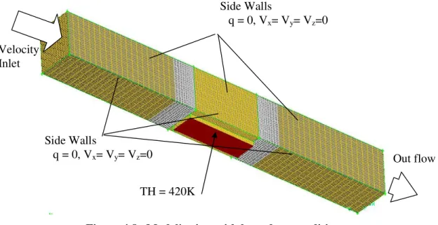
In this thesis, three models are considered. The heat exchanger domain consists of three
connected channels: Entrance section, pin-fin section and exit section. The pin-fin section
consists eight rows of in-line pin-fins with axes perpendicular to the flow, as shown in Figure
4.1. Three different pin shapes are considered: cylindrical, rectangular and drop-shaped. The
main geometrical dimensions that characterize the heat exchanger are the pin height (H), the
diameter of the cylindrical portion of the pin (D, for rectangular pin-fin this parameter is
considered as fin width), the streamwise pin spacing (∆) and the pin-tail length (Z). Figures
4.2 and 4.3 give more details on these parameters. The pin width (D) was kept constant at a
value equal to 5 mm and was considered as a reference length scale. The total pin-fin area is
equal for all pin-fins. The entrance section of the heat exchanger is composed of a rectangular
duct having 40D as length, 10D as width and 10D as height. The exit section is exactly the
same as the entrance section. The pin-fin section is composed of 8 solid pins that are attached
to a solid rectangular volume which is considered as heat source. Three different pin-fin
morphologies were investigated in this primary study.
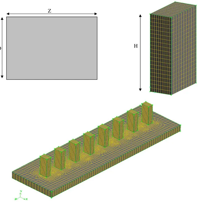
Figure 4.1 Heat exchanger domain
Figure 4.2 Studied morphologies: Cylindrical, Rectangular, Drop-Shaped
D
H
Z
H
D
Z
Z
D/2
H
L
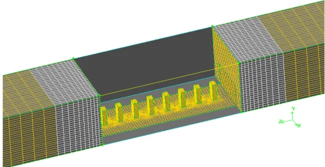
Entrance Section Exit Section Pin-Fin Section 200mm 100mm 200mm 50mm 50mmFigure 4.3 Studied morphologies: Cylindrical, Rectangular, Drop-Shaped
The entrance duct was constructed in front of the heat exchanger pin-fin section to ensure a
fully developed laminar flow condition at the entrance to this section. An exit duct was also
used to ensure well-mixed conditions at the exit plane. Both the entrance and exit duct are
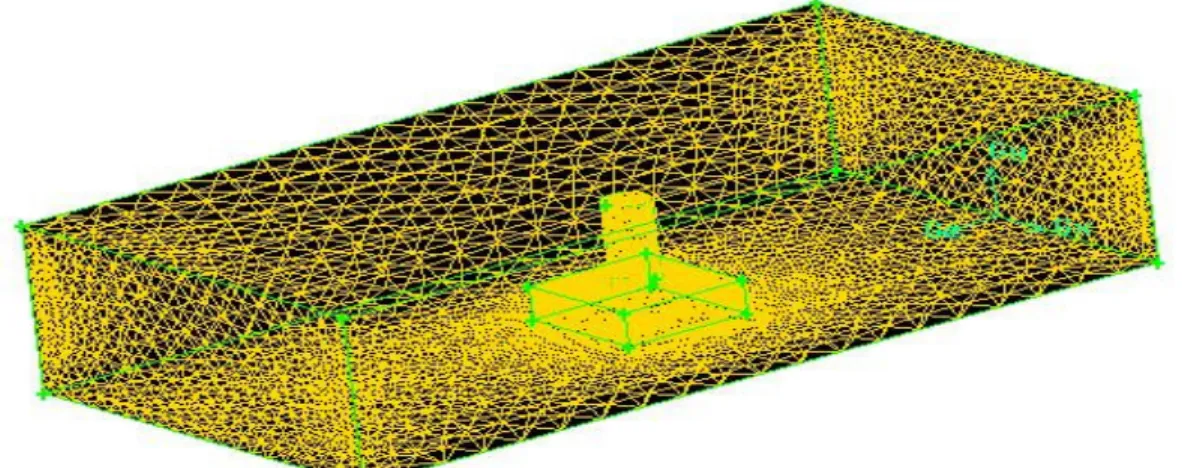
assumed to be adiabatic. Figure 4.4 shows one of the initially studied models in this study.
The model was constructed to study the sensitivity of different parameters on mesh quality.
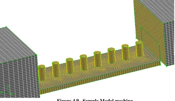
Figure 4.4 First model for sensibility analysis
HZ ∆
![Figure 1.5 Schematic diagrams of different heat sinks for tests [5]](https://thumb-eu.123doks.com/thumbv2/5dokorg/4833435.130515/14.918.173.749.327.558/figure-schematic-diagrams-different-heat-sinks-tests.webp)